EP3968476B1 - Système de support de chaîne de guidage - Google Patents
Système de support de chaîne de guidage Download PDFInfo
- Publication number
- EP3968476B1 EP3968476B1 EP20195904.6A EP20195904A EP3968476B1 EP 3968476 B1 EP3968476 B1 EP 3968476B1 EP 20195904 A EP20195904 A EP 20195904A EP 3968476 B1 EP3968476 B1 EP 3968476B1
- Authority
- EP
- European Patent Office
- Prior art keywords
- guiding chain
- chain
- mobile workstation
- guiding
- engine
- Prior art date
- Legal status (The legal status is an assumption and is not a legal conclusion. Google has not performed a legal analysis and makes no representation as to the accuracy of the status listed.)
- Active
Links
Images

Classifications
-
- A—HUMAN NECESSITIES
- A01—AGRICULTURE; FORESTRY; ANIMAL HUSBANDRY; HUNTING; TRAPPING; FISHING
- A01K—ANIMAL HUSBANDRY; AVICULTURE; APICULTURE; PISCICULTURE; FISHING; REARING OR BREEDING ANIMALS, NOT OTHERWISE PROVIDED FOR; NEW BREEDS OF ANIMALS
- A01K1/00—Housing animals; Equipment therefor
- A01K1/02—Pigsties; Dog-kennels; Rabbit-hutches or the like
- A01K1/03—Housing for domestic or laboratory animals
- A01K1/031—Cages for laboratory animals; Cages for measuring metabolism of animals
-
- B—PERFORMING OPERATIONS; TRANSPORTING
- B65—CONVEYING; PACKING; STORING; HANDLING THIN OR FILAMENTARY MATERIAL
- B65H—HANDLING THIN OR FILAMENTARY MATERIAL, e.g. SHEETS, WEBS, CABLES
- B65H75/00—Storing webs, tapes, or filamentary material, e.g. on reels
- B65H75/02—Cores, formers, supports, or holders for coiled, wound, or folded material, e.g. reels, spindles, bobbins, cop tubes, cans, mandrels or chucks
- B65H75/34—Cores, formers, supports, or holders for coiled, wound, or folded material, e.g. reels, spindles, bobbins, cop tubes, cans, mandrels or chucks specially adapted or mounted for storing and repeatedly paying-out and re-storing lengths of material provided for particular purposes, e.g. anchored hoses, power cables
- B65H75/36—Cores, formers, supports, or holders for coiled, wound, or folded material, e.g. reels, spindles, bobbins, cop tubes, cans, mandrels or chucks specially adapted or mounted for storing and repeatedly paying-out and re-storing lengths of material provided for particular purposes, e.g. anchored hoses, power cables without essentially involving the use of a core or former internal to a stored package of material, e.g. with stored material housed within casing or container, or intermittently engaging a plurality of supports as in sinuous or serpentine fashion
- B65H75/368—Cores, formers, supports, or holders for coiled, wound, or folded material, e.g. reels, spindles, bobbins, cop tubes, cans, mandrels or chucks specially adapted or mounted for storing and repeatedly paying-out and re-storing lengths of material provided for particular purposes, e.g. anchored hoses, power cables without essentially involving the use of a core or former internal to a stored package of material, e.g. with stored material housed within casing or container, or intermittently engaging a plurality of supports as in sinuous or serpentine fashion with pulleys
-
- A—HUMAN NECESSITIES
- A01—AGRICULTURE; FORESTRY; ANIMAL HUSBANDRY; HUNTING; TRAPPING; FISHING
- A01G—HORTICULTURE; CULTIVATION OF VEGETABLES, FLOWERS, RICE, FRUIT, VINES, HOPS OR SEAWEED; FORESTRY; WATERING
- A01G18/00—Cultivation of mushrooms
- A01G18/60—Cultivation rooms; Equipment therefor
-
- A—HUMAN NECESSITIES
- A01—AGRICULTURE; FORESTRY; ANIMAL HUSBANDRY; HUNTING; TRAPPING; FISHING
- A01K—ANIMAL HUSBANDRY; AVICULTURE; APICULTURE; PISCICULTURE; FISHING; REARING OR BREEDING ANIMALS, NOT OTHERWISE PROVIDED FOR; NEW BREEDS OF ANIMALS
- A01K67/00—Rearing or breeding animals, not otherwise provided for; New or modified breeds of animals
- A01K67/30—Rearing or breeding invertebrates
- A01K67/34—Insects
- A01K67/36—Industrial rearing of insects, e.g. insect farms
- A01K67/362—Containers or crates
-
- B—PERFORMING OPERATIONS; TRANSPORTING
- B65—CONVEYING; PACKING; STORING; HANDLING THIN OR FILAMENTARY MATERIAL
- B65H—HANDLING THIN OR FILAMENTARY MATERIAL, e.g. SHEETS, WEBS, CABLES
- B65H59/00—Adjusting or controlling tension in filamentary material, e.g. for preventing snarling; Applications of tension indicators
- B65H59/38—Adjusting or controlling tension in filamentary material, e.g. for preventing snarling; Applications of tension indicators by regulating speed of driving mechanism of unwinding, paying-out, forwarding, winding, or depositing devices, e.g. automatically in response to variations in tension
- B65H59/384—Adjusting or controlling tension in filamentary material, e.g. for preventing snarling; Applications of tension indicators by regulating speed of driving mechanism of unwinding, paying-out, forwarding, winding, or depositing devices, e.g. automatically in response to variations in tension using electronic means
-
- B—PERFORMING OPERATIONS; TRANSPORTING
- B65—CONVEYING; PACKING; STORING; HANDLING THIN OR FILAMENTARY MATERIAL
- B65H—HANDLING THIN OR FILAMENTARY MATERIAL, e.g. SHEETS, WEBS, CABLES
- B65H63/00—Warning or safety devices, e.g. automatic fault detectors, stop-motions ; Quality control of the package
- B65H63/04—Warning or safety devices, e.g. automatic fault detectors, stop-motions ; Quality control of the package responsive to excessive tension or irregular operation of apparatus
-
- F—MECHANICAL ENGINEERING; LIGHTING; HEATING; WEAPONS; BLASTING
- F16—ENGINEERING ELEMENTS AND UNITS; GENERAL MEASURES FOR PRODUCING AND MAINTAINING EFFECTIVE FUNCTIONING OF MACHINES OR INSTALLATIONS; THERMAL INSULATION IN GENERAL
- F16G—BELTS, CABLES, OR ROPES, PREDOMINANTLY USED FOR DRIVING PURPOSES; CHAINS; FITTINGS PREDOMINANTLY USED THEREFOR
- F16G13/00—Chains
- F16G13/12—Hauling- or hoisting-chains so called ornamental chains
- F16G13/16—Hauling- or hoisting-chains so called ornamental chains with arrangements for holding electric cables, hoses, or the like
-
- H—ELECTRICITY
- H02—GENERATION; CONVERSION OR DISTRIBUTION OF ELECTRIC POWER
- H02G—INSTALLATION OF ELECTRIC CABLES OR LINES, OR OF COMBINED OPTICAL AND ELECTRIC CABLES OR LINES
- H02G11/00—Arrangements of electric cables or lines between relatively-movable parts
- H02G11/006—Arrangements of electric cables or lines between relatively-movable parts using extensible carrier for the cable, e.g. self-coiling spring
-
- A—HUMAN NECESSITIES
- A01—AGRICULTURE; FORESTRY; ANIMAL HUSBANDRY; HUNTING; TRAPPING; FISHING
- A01G—HORTICULTURE; CULTIVATION OF VEGETABLES, FLOWERS, RICE, FRUIT, VINES, HOPS OR SEAWEED; FORESTRY; WATERING
- A01G9/00—Cultivation in receptacles, forcing-frames or greenhouses; Edging for beds, lawn or the like
- A01G9/14—Greenhouses
- A01G9/143—Equipment for handling produce in greenhouses
-
- Y—GENERAL TAGGING OF NEW TECHNOLOGICAL DEVELOPMENTS; GENERAL TAGGING OF CROSS-SECTIONAL TECHNOLOGIES SPANNING OVER SEVERAL SECTIONS OF THE IPC; TECHNICAL SUBJECTS COVERED BY FORMER USPC CROSS-REFERENCE ART COLLECTIONS [XRACs] AND DIGESTS
- Y02—TECHNOLOGIES OR APPLICATIONS FOR MITIGATION OR ADAPTATION AGAINST CLIMATE CHANGE
- Y02A—TECHNOLOGIES FOR ADAPTATION TO CLIMATE CHANGE
- Y02A40/00—Adaptation technologies in agriculture, forestry, livestock or agroalimentary production
- Y02A40/10—Adaptation technologies in agriculture, forestry, livestock or agroalimentary production in agriculture
- Y02A40/25—Greenhouse technology, e.g. cooling systems therefor
Definitions
- the present invention relates to the domain of guiding chain carrier systems, more precisely to a system to deploy and to store a guiding chain guiding flexible cables and/or pipelines connected to a single static connection point on one hand and to a mobile workstation on another hand.
- the mobile workstation needs to operate on a work surface.
- the amplitude of the movement of the mobile workstation is increased as the work surface increases. So, the required length of the guiding chain is extended, and the guiding chain length may be over several meters to reach the extreme operation location furthest from the static connection point.
- the guiding chain is deployed or retracted according to the movement of the mobile workstation in order to support the flexible cables and/or pipelines and to allow the mobile workstation to move from the operation location nearest to the static connection point up to the operation location furthest away from the static connection point.
- the guiding chain ensures the guiding of flexible cables and/or pipelines (electric and communication cables, water tube, compressed air tube, etc.) at any location of the useful area that the mobile workstation needs to reach.
- Guiding chains are well-known for guiding hoses, cables, pipelines or the like.
- One example is commercialized under the trademark "Igus”.
- Guiding chains are made of numerous chain links connected to one another in articulated manner, as disclosed in the document US 2003/0000198 A1 .
- the guiding chain has to be stored when the mobile workstation is near the static connection point.
- the guiding chain also must be deployed when the mobile workstation is near the operation location furthest away from the static connection point.
- a return wheel with a guiding chain wrapped at least partially thereon said return wheel including a chain wheel which rolls freely upon a part of said guiding chain and is driven by movement of said guiding chain, wherein surplus length of guiding chain is taken up and laid down in a loop during movement of said workstation.
- Document US 4 600 817 is an example where a mobile workstation is connected by flexible pipelines to a static connection point.
- this known guiding system comprises a guiding chain bent in two opposite directions once installed in the guiding system, which is a very rare and very expensive guiding chain.
- This known guiding system also offers no protection against the folding of the guiding chain.
- a simple winding of a guiding chain longer than few meters around an axis takes up a volume whose dimensions are incompatible with the common size of sheds. No realistic solution exists to completely deploy or retract a guiding chain longer than 14 meters.
- the invention thus aims at deploying and storing a guiding chain bent in only one direction, simply, safely and efficiently, whatever the position of the mobile workstation is between the operation location closest to the static connection point and the operation location furthest from the static connection point, avoiding any folding of the guiding chain whatever the length of the guiding chain is.
- the invention relates to a guiding chain carrier system as described in claim 1.
- the static connection point is the place where the different supplies are delivered (electricity, water, compressed air, etc.).
- the different supplies are all grouped on the same element with similar orientation and are available through an element connectable to the end of a pipeline and/or cable.
- a mobile workstation is an operation device able to perform several actions in a workspace.
- the mobile workstation can humidify, ventilate, position and remove a substrate, deliver food, etc.
- the invention makes it possible to deploy and to store the guiding chain simply, efficiently and safely.
- straight guiding chain means that the guiding chain can be bent in the same plane but not folded.
- the straight guiding chain can be bent, as long as the guiding chain remains in the same plane.
- the plane of the guiding chain is usually vertical.
- folding the guiding chain may result into damages to the guiding chain itself, and also to the cables and pipelines.
- the space required for storing the guiding chain is also an important criterion to optimize the installation. Increasing the work surface results in an increase of the distance traveled by the mobile workstation, which results in an increase of the length of the guiding chain. The risk of folding the guiding chain and the space required for storing increase with the length of the guiding chain.
- one element "close to" another element means that the elements have the same orientation and are located at a limited distance.
- the limited distance is the minimum distance possible while ensuring a stable fixation of each element during operation.
- the invention relates to a guiding chain carrier system as described in claim 2.
- the length of the guiding chain must be at least the whole length of one work area plus the length to reach the work area furthest from the static connection point.
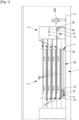
- Fig. 1 shows an installation according to one possible embodiment of the invention.
- the installation is a breeding installation 2 to breed insects.
- the breeding installation 2 comprises a plurality of work areas 3, also named culture areas 3 in the case of breeding, which are disposed one above the other.
- the breeding installation 2 shown is in the middle of a breeding cycle, all the culture areas are loaded with substrate.
- the first culture area 3 is installed about one meter above the ground X.
- the other culture areas 3 are positioned above the first culture area 3 .
- all culture areas 3 are identical or similar.
- a given culture area 3 is disposed horizontally. It may be of a plurality of meter long, for example 6 meter long, or even longer than that.
- the substrate 100 is loaded and unloaded respectively at the beginning and at the end of one breeding cycle.
- the installation 2 comprises a guiding chain carrier system 1 which will be described in more details below.
- One lift system 5 is provided to vertically lift a mobile workstation 6 .
- the lift system 5 is installed at one lateral side of the culture areas 3 .
- Each culture area 3 is made of stainless-steel.
- the structure of each culture area 3 is a rectangular plate.
- the longitudinal edges 31 of each culture area 3 have flanges in order to retain a substrate on the upper surface of the culture area 3 .
- the lateral edges of each culture area 3 are flat to facilitate the loading and unloading of the substrate 100 .
- On the lower surface of each stainless-steel rectangular plate a guiding rail 4 is provided.
- the guiding rail 4 is parallel to the longitudinal edges.
- the guiding rail 4 extends longitudinally, is straight, and positioned in the middle of the lower surface of the stainless-steel rectangular plate.
- a first engine installed on a mobile workstation 6 can move the mobile workstation 6 above culture areas 3 .
- the mobile workstation 6 is connected to cables and pipelines.
- the cables and pipelines are of three types:
- the mobile workstation 6 is connected by an ethernet cable to send and receive data.
- the mobile workstation 6 is also connected to a controller.
- the mobile workstation has suspension wheels 11 .
- the said suspension wheels 11 are positioned on a rail section 23 of the lift system 5 connectable to any of the guide rails 4.
- the lift system 5 positions the rail section 23 in continuity with the guide rails 4 corresponding to a culture area 3 selected by an operator 100 or through a processor programmed by the operator to repeat cycles of movements of the mobile workstation.
- guide rails 41 are above each longitudinal edge 31 of the working area.
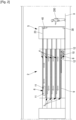
- the mobile workstation not shown on the figure 4 , has supporting wheels instead of suspension wheels 11 as in the figure 1 embodiment.
- the lift system operation is similar as described above.
- a static connection area 7 is located under the first culture area 3.
- the static connection area 7 is a vertical side of a wall where all the socketsladed by these sources of energy, water, and data exchange are grouped.
- the position of the static connection area 7 is approximately halfway between the ground and the first culture area.
- the static connection area 7 is close to the lateral side of the culture areas where a lift system 5 is located.
- the static connection area 7 is oriented towards the opposite lateral side of the culture areas 3 .
- the cables and pipelines are connected to the static connection area 7.
- the lengths of the said cables and pipelines are enough to let the mobile workstation 6 move to an operation location furthest from the static connection area 7.
- the guiding chain 20 is made of numerous chain links of hollow parallelepiped structure connected to one another according to an axis of rotation. Each rotation axis is located close to one single side of the guiding chain 20.
- the minimum possible angle between two contiguous chain links without damaging the 1-dimension guiding chain 20 is 150° degrees.
- the maximum possible angle between two contiguous chain links without damaging the 1-dimension guiding chain 20 is 190°. All the rotation axis are parallel.
- flexibility operates essentially on only one side of the guiding chain 20, such a guiding chain is named 1-dimension guiding chain.
- the final assembled 1-dimension guiding chain 20 is a corridor where cables and/or pipelines can be threaded.
- the first extremity 21 of the 1-dimension guiding chain is fixed on the mobile workstation 6, on an axis fixed perpendicular of one lateral side of the mobile workstation.
- the second extremity 22 of the 1-dimension guiding chain 20 is fixed on the static connection area 7.
- the 1-dimension guiding chain 20 is installed vertically in a position comprising several windings all oriented towards the only flexible side of the guiding chain 20. This position results of the interaction between the 1-dimension guiding chain 20 and three chain pulleys 10, 30, 40 positioned in the vertical plane defined by the 1-dimension guiding chain.
- a compensation rail 9 is provided fixed under the culture area 3 closest to the ground X level.
- a compensation trolley 8 comprises four sustaining wheels 12 and a pinion 82 interacting with a rack 9 , and a second engine 81 able to apply a compensation force on the pinion 82 .
- the compensation trolley 8 comprises also the first chain pulley 10.
- the first chain pulley 10 is mounted on a longitudinal side of the compensation trolley 8 , its axis of rotation is connected to the compensation trolley 8 by a lateral structure 83 comprising several rods and a metal plate protruding on one longitudinal side of the compensation trolley 8 .
- the height of the lateral structure 83 is less than the diameter of the chain pulley 10 and the chain pulley 10 is mounted on this structure to be both higher and lower than this structure.
- the guiding chain 20 is putting pressure on the structure 83 .
- the structure 83 is more resistant to pressure force than to stretching force.
- a supporting wheel 85 is added on the lateral structure 83 , at the opposite side and at an upper position of the first chain pulley 10 , on the lateral structure 83.
- the compensation trolley 8 is keeping the orientation of the guiding chain 20 according to a U-turn configuration.
- the guiding chain 20 is starting horizontally from the static connection area 7 , wrapping around the first chain pulley 10 , horizontally and below the static connection area 7 .
- the compensation trolley 8 is moving thanks to the sustaining wheels 12 supported on the rack 9 .
- the compensation trolley 8 comprises the second engine 81 applying a force to retain the movement of the compensation trolley 8 to maintain the guiding chain 20 straight.
- the compensation trolley 8 is connected to a source of electric energy by cables guided by a secondary guiding chain not represented. Retaining force is when the mobile workstation 6 is getting closer to the static connection area 7; the retaining force is reduced when the mobile workstation 6 is getting further from the static connection area 7. Thus, there is no folding and nor stretching of the guiding chain 20.
- the guiding chain 20 After passing between the ground X and the static connection area 7 , the guiding chain 20 passes below the lift system 5 and reaches a second chain pulley 30 attached to the installation 2 .
- the second chain pulley 30 is changing the orientation of the guiding chain 20 from horizontal to vertical.
- the second chain pulley 30 is vertically aligned with a third chain pulley 40 .
- the third chain pulley 40 is attached to the vertical movable part of the lift system 5 comprising a support section 23 able to support the mobile workstation 6.
- the third chain pulley 40 is changing the guiding chain 20 orientation from vertical to horizontal.
- the lift system 5 can be controlled directly by the operator 100 or through the processor programmed by the operator to repeat cycles of movements of the mobile workstation.
- the same mobile workstation can thus operate on all the culture areas 3 by selecting one level of the culture area 3 , then another one.
- the lift system 5 reached the furthest position to work on the culture area 3.
- the retaining force is applied on the guiding chain by the second engine 81 through the interaction between the pinion 82 and the track 9.
- the retaining force to be applied is calculated by the controller based on the values of the signals sent by or to the first engine.
- the compensating system comprises a controller which is monitoring several signals and generates several command signals according to three different processes.
- the first movement process also named normal horizontal process, is described here below:
- the initial phase is a blocked configuration wherein both first and second engines are blocked in rotation and the mobile workstation is at a standby position illustrated figure 1 .
- the controller receives an order to move the mobile workstation 6 and to perform actions among several possible actions.
- the controller analyzes this information and calculates as a result a first command signal sent to the first engine.
- the first engine generates a first representative signal of its movement.
- the controller when it receives the first representative signal, it generates a second command signal to the second engine 81 .
- the second command signal intensity is calculated to move the compensating trolley 8 at half speed and opposite direction compared to the movement of the mobile workstation 6.
- the controller sends to the mobile workstation 6 a command signal to execute the actions.
- the controller sends the order to move back the mobile workstation 6 and to stop the first engine and the second engine 81 in the initial standby position.
- a second movement process is added twice , before and after the horizontal process.
- the second movement process also named normal vertical process, is described here below.
- the initial phase is when the mobile workstation is completely supported by the vertically movable part 23.
- the controller receives an order to move the mobile workstation 6 to a different level of working area 3.
- the controller analyzes this information and calculates as a result a third command signal to a third engine 91 to move the movable part 23 upward or downward, in the direction toward the required level.
- the third engine 91 generates a third representative signal of its movement.
- the controller when it receives the third representative signal, it generates a second command signal to the second engine 81.
- the second command signal intensity is calculated to move the compensating trolley 8 at half speed compared to the speed of the movable part 23.
- the direction of the compensating trolley 8 is closer to the lift system 5 if the movement of the vertical movable part 23 is an upward movement.
- the direction of the compensating trolley 8 is further away from the lift system 5 if the movement of the vertical movable part 23 is a downward movement.
- the lift system 5 sends to the controller a command signal to indicate the level reached by the vertical movable part 23.
- the controller sends the order to stop and block the third engine 91 and the second engine 81.
- a third movement process also named emergency stop process, is launched as described here below.
- the initial phase is when one of the first, second or(and) third engine(s) is(are) sending to the controller a resistance signal outside of the normal range.
- the controller immediately interrupts any ongoing movement command signal.
- the controller sends a signal to block all the engines.
- the controller activates a red light and generates an alarm sound.
- the mobile workstation comprising four sustaining wheels 11 is located on the lift system 5 , at the level of the first culture area.
- a flexible security cable made of steel is following the same path as the guiding chain 20 .
- the end points of the security cable are fixed to the same elements as the end points 21, 22 of the guiding chain 20.
- the length of the security cable is slightly shorter than the guiding chain 20. This difference of length between the security cable and the guiding chain 20 is not enough to generate any folding of the guiding chain 20. Nevertheless, when a tension force appears, it is largely supported by the security cable instead of the guiding chain 20.
- the chain pulleys are positioned on one longitudinal side of the compensation trolley and on one longitudinal side of the mobile workstation.
- the said longitudinal side are the sides parallel to the direction of movement of the mobile workstation.
- the path segments followed by the guiding chain comprises several longitudinal lengthwise cases for storing the guiding chain 20.
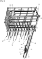
- One longitudinal lengthwise case is shown on figure 4 .
- a longitudinal lengthwise case 90 is fixed on the installation 2, as illustrated on figure 4 .
- the said longitudinal lengthwise case 90 is holding the guiding chain between the first chain pulley 10 and the second chain pulley 30.
- Similar longitudinal lengthwise case not represented is fixed on the installation to hold the guiding chain between the third pulley 40 and the mobile workstation 6.
- the controller keeps the information of the current location reached by the mobile workstation 6.
- the controller receives an instruction comprising a dedicated level of work area 3.
- the instruction is kept in the memory of the controller in a row of standby instructions. If the mobile workstation 6 is not on the vertical movable part 23 , and if the mobile workstation 6 is not yet at the level corresponding to the dedicated work area 3 , the controller first launches the normal vertical process.
- the controller launches a first normal horizontal process.
- the first normal horizontal process direction is toward the side opposite to the side where the lift system 5 is set up.
- the installation 2 sends a first detection signal when the mobile workstation has reached the opposite end of the work area 3.
- the controller receives the first detection signal, the controller stops the first normal horizontal process and launches a second normal horizontal process.
- the direction of the second normal horizontal process is opposite to the first normal horizontal process.
- a second detection signal is sent to the controller.
- the controller receives this second detection signal, the controller stops the second normal horizontal process. In case there is not another instruction in standby, the controller launches a normal vertical process in the direction to the lowest work area 3 .
Landscapes
- Life Sciences & Earth Sciences (AREA)
- Environmental Sciences (AREA)
- Zoology (AREA)
- Engineering & Computer Science (AREA)
- Animal Behavior & Ethology (AREA)
- Animal Husbandry (AREA)
- Biodiversity & Conservation Biology (AREA)
- General Engineering & Computer Science (AREA)
- Mycology (AREA)
- Quality & Reliability (AREA)
- Mechanical Engineering (AREA)
- Health & Medical Sciences (AREA)
- Clinical Laboratory Science (AREA)
- General Health & Medical Sciences (AREA)
- Handcart (AREA)
- Control Of Position, Course, Altitude, Or Attitude Of Moving Bodies (AREA)
- Mushroom Cultivation (AREA)
- Storing, Repeated Paying-Out, And Re-Storing Of Elongated Articles (AREA)
- Supports For Pipes And Cables (AREA)
- Electric Cable Arrangement Between Relatively Moving Parts (AREA)
- Platform Screen Doors And Railroad Systems (AREA)
- Warehouses Or Storage Devices (AREA)
Claims (2)
- Installation (2) comprenant un système porte-chaîne de guidage (1) pour déployer et stocker sans plier ladite chaîne de guidage et des câbles souples d'alimentation et/ou des canalisations, ledit système porte-chaîne de guidage comprenant :Un poste de travail mobile (6) déplaçable au-dessus d'une surface de travail (3) par un premier moteur et relié auxdits câbles et/ou canalisations,Au moins une chaîne de guidage (20), reliée à une zone de connexion statique (7) à une extrémité et au poste de travail mobile (6) à l'autre extrémité de celle-ci, pour supporter lesdits câbles et/ou canalisations ;au moins un chariot de compensation (8) comprenant au moins une première poulie à chaîne (10) se déplaçant selon les mouvements de ladite chaîne de guidage (20) enroulée au moins partiellement sur la première poulie à chaîne (10) et comprenant un système de compensation, ledit chariot de compensation (8) est situé sous la surface de travail (3) et mobile par un deuxième moteur et le système de compensation est apte à générer une force de résistance calculée par un contrôleur à partir des valeurs des signaux envoyés par ou vers le premier moteur afin de maintenir la chaîne de guidage (20) droite tandis que le poste de travail mobile (6) se déplace d'un emplacement d'opération le plus proche de la zone de connexion statique (7) jusqu'à un emplacement d'opération le plus éloigné de la zone de connexion statique (7)dans lequel la surface de travail est divisée en plusieurs zones de travail (3) les unes sous les autres, dans lequel l'installation (2) comprend en outre un système élévateur (5) comprenant :Une partie mobile verticalement (23) apte à recevoir, supporter et amener le poste de travail mobile d'un niveau de zone de travail (3) à un autre niveau de zone de travail (3),un troisième moteur (91) pour déplacer ladite partie mobile (23) et le troisième moteur (91) est configuré pour coopérer avec le deuxième moteur (81) pour éviter le pliage et la rupture de la chaîne de guidage (20),Au moins deux autres poulies à chaîne (30, 40), la deuxième poulie à chaîne (30) fixée sous la position la plus basse du poste de travail mobile (8) pouvant tourner selon les mouvements de ladite chaîne de guidage (6) enroulée au moins partiellement sur celle-ci, pour changer la direction de l'axe de la chaîne de guidage (6) et la troisième poulie de chaîne (40) fixée sur la section mobile (23).
- Installation (2) selon la revendication 1 utilisée dans les domaines de l'élevage d'insectes, de la culture des champignons ou de la logistique.
Priority Applications (6)
| Application Number | Priority Date | Filing Date | Title |
|---|---|---|---|
| EP20195904.6A EP3968476B1 (fr) | 2020-09-14 | 2020-09-14 | Système de support de chaîne de guidage |
| US18/043,895 US12570497B2 (en) | 2020-09-14 | 2021-09-13 | Guiding chain carrier system |
| JP2023516832A JP7835738B2 (ja) | 2020-09-14 | 2021-09-13 | 誘導チェーン運搬システム |
| CN202180076495.4A CN116802419A (zh) | 2020-09-14 | 2021-09-13 | 导向链承载系统 |
| PCT/EP2021/075138 WO2022053695A1 (fr) | 2020-09-14 | 2021-09-13 | Système de support de chaîne de guidage |
| BR112023004538A BR112023004538A2 (pt) | 2020-09-14 | 2021-09-13 | Sistema de transporte de correia de guia |
Applications Claiming Priority (1)
| Application Number | Priority Date | Filing Date | Title |
|---|---|---|---|
| EP20195904.6A EP3968476B1 (fr) | 2020-09-14 | 2020-09-14 | Système de support de chaîne de guidage |
Publications (3)
| Publication Number | Publication Date |
|---|---|
| EP3968476A1 EP3968476A1 (fr) | 2022-03-16 |
| EP3968476B1 true EP3968476B1 (fr) | 2023-08-23 |
| EP3968476C0 EP3968476C0 (fr) | 2023-08-23 |
Family
ID=72474198
Family Applications (1)
| Application Number | Title | Priority Date | Filing Date |
|---|---|---|---|
| EP20195904.6A Active EP3968476B1 (fr) | 2020-09-14 | 2020-09-14 | Système de support de chaîne de guidage |
Country Status (6)
| Country | Link |
|---|---|
| US (1) | US12570497B2 (fr) |
| EP (1) | EP3968476B1 (fr) |
| JP (1) | JP7835738B2 (fr) |
| CN (1) | CN116802419A (fr) |
| BR (1) | BR112023004538A2 (fr) |
| WO (1) | WO2022053695A1 (fr) |
Families Citing this family (4)
| Publication number | Priority date | Publication date | Assignee | Title |
|---|---|---|---|---|
| CN113243227B (zh) * | 2021-05-21 | 2022-08-02 | 李晟 | 具有轨道、托盘的高密度种植架及后处理系统和控制系统 |
| CN114145183B (zh) * | 2021-10-29 | 2023-08-08 | 山东省农业机械科学研究院 | 一种食用菌菌棒打孔增氧注水一体化装置及工作方法 |
| IT202100027740A1 (it) * | 2021-10-29 | 2023-04-29 | Ono Exponential Farming S R L | Sistema di fattoria verticale |
| CN117125547B (zh) * | 2023-07-28 | 2026-04-28 | 湖州晨净科技服务有限公司 | 一种拖链式物料输送装置以及密封式昆虫养殖设备 |
Family Cites Families (18)
| Publication number | Priority date | Publication date | Assignee | Title |
|---|---|---|---|---|
| DE1059066B (de) * | 1957-03-13 | 1959-06-11 | Siemens Ag | Einrichtung zur Aufrechterhaltung eines konstanten Zuges bei einer elektrischen Verbindungsleitung zu beweglichen Teilen von Maschinen |
| SU362161A1 (ru) | 1970-12-14 | 1972-12-13 | Цепь для поддержания гибкого элемента | |
| GB1359168A (en) * | 1971-05-21 | 1974-07-10 | Glaverbel | Panels incorporating a glass sheet and the manufacture thereof |
| DE2362463B2 (de) | 1973-12-15 | 1978-03-16 | Kabelschlepp Gmbh, 5900 Siegen | Anordnung für die Führung von Energieleitungen |
| US4023695A (en) * | 1974-08-13 | 1977-05-17 | Carew Victor E | Mobile stacker with a work station thereon |
| DE2832567C2 (de) * | 1978-07-25 | 1985-03-21 | Walter 6670 St Ingbert Port | Vorrichtung zum Gespannthalten eines Seiles oder desgleichen fadenförmigen Materials |
| DE3241924C2 (de) | 1982-11-12 | 1986-09-25 | Schubert & Salzer Maschinenfabrik Ag, 8070 Ingolstadt | Vorrichtung zum Führen von flexiblen Versorgungsleitungen |
| DE3806400A1 (de) | 1988-02-29 | 1989-09-07 | Igus Gmbh | Energiezufuehrungskette |
| AU635862B2 (en) | 1990-09-11 | 1993-04-01 | Best Diversified Products Pty Ltd | Improvements in and relating to extensible conveyors |
| JPH07213154A (ja) | 1994-02-07 | 1995-08-15 | Shinko Kogyo Kk | キノコ栽培施設及びキノコ栽培方法 |
| US5692984A (en) | 1994-12-09 | 1997-12-02 | Sr Engineering Company Limited | Flexible drive member for pulling and pushing and fluid-operated moving apparatus |
| JPH10220533A (ja) * | 1997-02-13 | 1998-08-21 | Fuji Eng Kk | 可撓性長尺物の保護装置 |
| DE20107003U1 (de) | 2001-04-23 | 2002-09-19 | Igus Spritzgußteile für die Industrie GmbH, 51147 Köln | Energieführungskette |
| US9272186B2 (en) * | 2008-08-22 | 2016-03-01 | Alton Reich | Remote adaptive motor resistance training exercise apparatus and method of use thereof |
| US9198403B2 (en) | 2013-07-31 | 2015-12-01 | Richard W. Carter | Removable wavemaker |
| JP6309220B2 (ja) * | 2013-08-12 | 2018-04-11 | 株式会社ダイヘン | 搬送システム |
| KR20180093258A (ko) | 2016-12-30 | 2018-08-22 | 강성광 | 식물공장 자동화 시스템 및 그 구성방법 |
| KR101849162B1 (ko) * | 2017-09-08 | 2018-05-31 | 주식회사 표고애 | 버섯 병재배 자동화 시스템의 터너 컨베이어 유닛 |
-
2020
- 2020-09-14 EP EP20195904.6A patent/EP3968476B1/fr active Active
-
2021
- 2021-09-13 WO PCT/EP2021/075138 patent/WO2022053695A1/fr not_active Ceased
- 2021-09-13 JP JP2023516832A patent/JP7835738B2/ja active Active
- 2021-09-13 BR BR112023004538A patent/BR112023004538A2/pt unknown
- 2021-09-13 US US18/043,895 patent/US12570497B2/en active Active
- 2021-09-13 CN CN202180076495.4A patent/CN116802419A/zh active Pending
Also Published As
| Publication number | Publication date |
|---|---|
| US20230312302A1 (en) | 2023-10-05 |
| WO2022053695A1 (fr) | 2022-03-17 |
| US12570497B2 (en) | 2026-03-10 |
| EP3968476A1 (fr) | 2022-03-16 |
| EP3968476C0 (fr) | 2023-08-23 |
| JP7835738B2 (ja) | 2026-03-25 |
| CN116802419A (zh) | 2023-09-22 |
| JP2023542663A (ja) | 2023-10-11 |
| BR112023004538A2 (pt) | 2023-04-04 |
Similar Documents
| Publication | Publication Date | Title |
|---|---|---|
| US12570497B2 (en) | Guiding chain carrier system | |
| US20130133982A1 (en) | Hoist | |
| US7931133B2 (en) | System for self-adjusting height and direction of a movable power cable | |
| EP3199481B1 (fr) | Appareil de déroulement de câbles sur les fonds marins et procédé de fonctionnement d'un appareil de déroulement de câbles sur les fonds marins | |
| EP2636887A1 (fr) | Appareil de génération hydroélectrique | |
| CN103855639A (zh) | 在航空器上安装布线线束的方法及实施所述方法的工具 | |
| WO2016171556A1 (fr) | Système de culture, par exemple pour des champignons, et procédé associé | |
| KR101715302B1 (ko) | 호이스트 크레인 래칭 장치 | |
| KR101497323B1 (ko) | 케이블 포설 장치 | |
| US10399647B2 (en) | Mechanism and arrangement for static and dynamic adjustment of submersible pumps associated with a floating platform | |
| JP2016124678A (ja) | 線材コイルの吊上げ用の吊上げ装置 | |
| KR20150087593A (ko) | 벨트를 이용한 케이블 포설장치 | |
| EP3573914B1 (fr) | Navire et procédé de manipulation d'un câble de grande longueur sur ledit navire | |
| RU2839657C1 (ru) | Несущая система направляющей цепи | |
| KR102062516B1 (ko) | 다중 물류이송 케이블 로봇 시스템 및 이를 이용한 물류 관리 방법 | |
| JP2026506018A (ja) | 把持アセンブリの深さ又は障害を決定するための方法及びシステム | |
| US9597795B2 (en) | System for moving a mobile tendon controlled platform robot | |
| KR101505641B1 (ko) | 거리센서를 이용한 전선포설로봇 동기화 장치 및 방법 | |
| US10220898B1 (en) | Apparatus for storing objects above a floor surface | |
| JP3292917B2 (ja) | 水中浮揚ライン収納装置 | |
| JP7252464B2 (ja) | 収納ラック | |
| NL9001981A (nl) | Automatische touwafwikkelinstallatie, in het bijzonder voor de tomatenteelt. | |
| WO2019038431A1 (fr) | Rouleau de chaîne et chariot supportant un tel rouleau de chaîne | |
| JPH06183684A (ja) | 上下動作装置における位置決め機構 | |
| KR101770060B1 (ko) | 무인운반차 |
Legal Events
| Date | Code | Title | Description |
|---|---|---|---|
| PUAI | Public reference made under article 153(3) epc to a published international application that has entered the european phase |
Free format text: ORIGINAL CODE: 0009012 |
|
| STAA | Information on the status of an ep patent application or granted ep patent |
Free format text: STATUS: REQUEST FOR EXAMINATION WAS MADE |
|
| 17P | Request for examination filed |
Effective date: 20210924 |
|
| AK | Designated contracting states |
Kind code of ref document: A1 Designated state(s): AL AT BE BG CH CY CZ DE DK EE ES FI FR GB GR HR HU IE IS IT LI LT LU LV MC MK MT NL NO PL PT RO RS SE SI SK SM TR |
|
| STAA | Information on the status of an ep patent application or granted ep patent |
Free format text: STATUS: EXAMINATION IS IN PROGRESS |
|
| 17Q | First examination report despatched |
Effective date: 20221111 |
|
| REG | Reference to a national code |
Ref country code: DE Ref legal event code: R079 Free format text: PREVIOUS MAIN CLASS: H02G0011000000 Ipc: B65H0075360000 Ref document number: 602020016120 Country of ref document: DE |
|
| RIC1 | Information provided on ipc code assigned before grant |
Ipc: A01K 1/03 20060101ALN20230126BHEP Ipc: A01G 9/14 20060101ALN20230126BHEP Ipc: B65H 59/38 20060101ALI20230126BHEP Ipc: F16G 13/16 20060101ALI20230126BHEP Ipc: H02G 11/00 20060101ALI20230126BHEP Ipc: B65H 75/36 20060101AFI20230126BHEP |
|
| GRAP | Despatch of communication of intention to grant a patent |
Free format text: ORIGINAL CODE: EPIDOSNIGR1 |
|
| STAA | Information on the status of an ep patent application or granted ep patent |
Free format text: STATUS: GRANT OF PATENT IS INTENDED |
|
| INTG | Intention to grant announced |
Effective date: 20230328 |
|
| GRAS | Grant fee paid |
Free format text: ORIGINAL CODE: EPIDOSNIGR3 |
|
| GRAA | (expected) grant |
Free format text: ORIGINAL CODE: 0009210 |
|
| STAA | Information on the status of an ep patent application or granted ep patent |
Free format text: STATUS: THE PATENT HAS BEEN GRANTED |
|
| AK | Designated contracting states |
Kind code of ref document: B1 Designated state(s): AL AT BE BG CH CY CZ DE DK EE ES FI FR GB GR HR HU IE IS IT LI LT LU LV MC MK MT NL NO PL PT RO RS SE SI SK SM TR |
|
| REG | Reference to a national code |
Ref country code: GB Ref legal event code: FG4D |
|
| REG | Reference to a national code |
Ref country code: CH Ref legal event code: EP |
|
| REG | Reference to a national code |
Ref country code: IE Ref legal event code: FG4D |
|
| REG | Reference to a national code |
Ref country code: DE Ref legal event code: R096 Ref document number: 602020016120 Country of ref document: DE |
|
| U01 | Request for unitary effect filed |
Effective date: 20230831 |
|
| U07 | Unitary effect registered |
Designated state(s): AT BE BG DE DK EE FI FR IT LT LU LV MT NL PT SE SI Effective date: 20230911 |
|
| U20 | Renewal fee for the european patent with unitary effect paid |
Year of fee payment: 4 Effective date: 20230922 |
|
| PG25 | Lapsed in a contracting state [announced via postgrant information from national office to epo] |
Ref country code: GR Free format text: LAPSE BECAUSE OF FAILURE TO SUBMIT A TRANSLATION OF THE DESCRIPTION OR TO PAY THE FEE WITHIN THE PRESCRIBED TIME-LIMIT Effective date: 20231124 |
|
| PG25 | Lapsed in a contracting state [announced via postgrant information from national office to epo] |
Ref country code: IS Free format text: LAPSE BECAUSE OF FAILURE TO SUBMIT A TRANSLATION OF THE DESCRIPTION OR TO PAY THE FEE WITHIN THE PRESCRIBED TIME-LIMIT Effective date: 20231223 |
|
| PG25 | Lapsed in a contracting state [announced via postgrant information from national office to epo] |
Ref country code: RS Free format text: LAPSE BECAUSE OF FAILURE TO SUBMIT A TRANSLATION OF THE DESCRIPTION OR TO PAY THE FEE WITHIN THE PRESCRIBED TIME-LIMIT Effective date: 20230823 Ref country code: NO Free format text: LAPSE BECAUSE OF FAILURE TO SUBMIT A TRANSLATION OF THE DESCRIPTION OR TO PAY THE FEE WITHIN THE PRESCRIBED TIME-LIMIT Effective date: 20231123 Ref country code: IS Free format text: LAPSE BECAUSE OF FAILURE TO SUBMIT A TRANSLATION OF THE DESCRIPTION OR TO PAY THE FEE WITHIN THE PRESCRIBED TIME-LIMIT Effective date: 20231223 Ref country code: HR Free format text: LAPSE BECAUSE OF FAILURE TO SUBMIT A TRANSLATION OF THE DESCRIPTION OR TO PAY THE FEE WITHIN THE PRESCRIBED TIME-LIMIT Effective date: 20230823 Ref country code: GR Free format text: LAPSE BECAUSE OF FAILURE TO SUBMIT A TRANSLATION OF THE DESCRIPTION OR TO PAY THE FEE WITHIN THE PRESCRIBED TIME-LIMIT Effective date: 20231124 |
|
| PG25 | Lapsed in a contracting state [announced via postgrant information from national office to epo] |
Ref country code: PL Free format text: LAPSE BECAUSE OF FAILURE TO SUBMIT A TRANSLATION OF THE DESCRIPTION OR TO PAY THE FEE WITHIN THE PRESCRIBED TIME-LIMIT Effective date: 20230823 |
|
| PG25 | Lapsed in a contracting state [announced via postgrant information from national office to epo] |
Ref country code: ES Free format text: LAPSE BECAUSE OF FAILURE TO SUBMIT A TRANSLATION OF THE DESCRIPTION OR TO PAY THE FEE WITHIN THE PRESCRIBED TIME-LIMIT Effective date: 20230823 |
|
| PG25 | Lapsed in a contracting state [announced via postgrant information from national office to epo] |
Ref country code: SM Free format text: LAPSE BECAUSE OF FAILURE TO SUBMIT A TRANSLATION OF THE DESCRIPTION OR TO PAY THE FEE WITHIN THE PRESCRIBED TIME-LIMIT Effective date: 20230823 Ref country code: RO Free format text: LAPSE BECAUSE OF FAILURE TO SUBMIT A TRANSLATION OF THE DESCRIPTION OR TO PAY THE FEE WITHIN THE PRESCRIBED TIME-LIMIT Effective date: 20230823 Ref country code: ES Free format text: LAPSE BECAUSE OF FAILURE TO SUBMIT A TRANSLATION OF THE DESCRIPTION OR TO PAY THE FEE WITHIN THE PRESCRIBED TIME-LIMIT Effective date: 20230823 Ref country code: CZ Free format text: LAPSE BECAUSE OF FAILURE TO SUBMIT A TRANSLATION OF THE DESCRIPTION OR TO PAY THE FEE WITHIN THE PRESCRIBED TIME-LIMIT Effective date: 20230823 Ref country code: SK Free format text: LAPSE BECAUSE OF FAILURE TO SUBMIT A TRANSLATION OF THE DESCRIPTION OR TO PAY THE FEE WITHIN THE PRESCRIBED TIME-LIMIT Effective date: 20230823 |
|
| REG | Reference to a national code |
Ref country code: CH Ref legal event code: PL |
|
| REG | Reference to a national code |
Ref country code: DE Ref legal event code: R097 Ref document number: 602020016120 Country of ref document: DE |
|
| PG25 | Lapsed in a contracting state [announced via postgrant information from national office to epo] |
Ref country code: MC Free format text: LAPSE BECAUSE OF FAILURE TO SUBMIT A TRANSLATION OF THE DESCRIPTION OR TO PAY THE FEE WITHIN THE PRESCRIBED TIME-LIMIT Effective date: 20230823 |
|
| PLBE | No opposition filed within time limit |
Free format text: ORIGINAL CODE: 0009261 |
|
| STAA | Information on the status of an ep patent application or granted ep patent |
Free format text: STATUS: NO OPPOSITION FILED WITHIN TIME LIMIT |
|
| REG | Reference to a national code |
Ref country code: IE Ref legal event code: MM4A |
|
| PG25 | Lapsed in a contracting state [announced via postgrant information from national office to epo] |
Ref country code: IE Free format text: LAPSE BECAUSE OF NON-PAYMENT OF DUE FEES Effective date: 20230914 |
|
| PG25 | Lapsed in a contracting state [announced via postgrant information from national office to epo] |
Ref country code: CH Free format text: LAPSE BECAUSE OF NON-PAYMENT OF DUE FEES Effective date: 20230930 |
|
| 26N | No opposition filed |
Effective date: 20240524 |
|
| PG25 | Lapsed in a contracting state [announced via postgrant information from national office to epo] |
Ref country code: IE Free format text: LAPSE BECAUSE OF NON-PAYMENT OF DUE FEES Effective date: 20230914 Ref country code: CH Free format text: LAPSE BECAUSE OF NON-PAYMENT OF DUE FEES Effective date: 20230930 |
|
| U20 | Renewal fee for the european patent with unitary effect paid |
Year of fee payment: 5 Effective date: 20240722 |
|
| GBPC | Gb: european patent ceased through non-payment of renewal fee |
Effective date: 20240914 |
|
| PG25 | Lapsed in a contracting state [announced via postgrant information from national office to epo] |
Ref country code: GB Free format text: LAPSE BECAUSE OF NON-PAYMENT OF DUE FEES Effective date: 20240914 |
|
| PG25 | Lapsed in a contracting state [announced via postgrant information from national office to epo] |
Ref country code: CY Free format text: LAPSE BECAUSE OF FAILURE TO SUBMIT A TRANSLATION OF THE DESCRIPTION OR TO PAY THE FEE WITHIN THE PRESCRIBED TIME-LIMIT; INVALID AB INITIO Effective date: 20200914 |
|
| PG25 | Lapsed in a contracting state [announced via postgrant information from national office to epo] |
Ref country code: HU Free format text: LAPSE BECAUSE OF FAILURE TO SUBMIT A TRANSLATION OF THE DESCRIPTION OR TO PAY THE FEE WITHIN THE PRESCRIBED TIME-LIMIT; INVALID AB INITIO Effective date: 20200914 |
|
| U20 | Renewal fee for the european patent with unitary effect paid |
Year of fee payment: 6 Effective date: 20250924 |
|
| PG25 | Lapsed in a contracting state [announced via postgrant information from national office to epo] |
Ref country code: TR Free format text: LAPSE BECAUSE OF FAILURE TO SUBMIT A TRANSLATION OF THE DESCRIPTION OR TO PAY THE FEE WITHIN THE PRESCRIBED TIME-LIMIT Effective date: 20230823 |