EP3968736B1 - Système de prise de courant d'éclairage d'armoire - Google Patents
Système de prise de courant d'éclairage d'armoire Download PDFInfo
- Publication number
- EP3968736B1 EP3968736B1 EP21166025.3A EP21166025A EP3968736B1 EP 3968736 B1 EP3968736 B1 EP 3968736B1 EP 21166025 A EP21166025 A EP 21166025A EP 3968736 B1 EP3968736 B1 EP 3968736B1
- Authority
- EP
- European Patent Office
- Prior art keywords
- power
- lamp
- cabinet
- lamp holder
- wire
- Prior art date
- Legal status (The legal status is an assumption and is not a legal conclusion. Google has not performed a legal analysis and makes no representation as to the accuracy of the status listed.)
- Active
Links
Images

Classifications
-
- F—MECHANICAL ENGINEERING; LIGHTING; HEATING; WEAPONS; BLASTING
- F21—LIGHTING
- F21S—NON-PORTABLE LIGHTING DEVICES; SYSTEMS THEREOF; VEHICLE LIGHTING DEVICES SPECIALLY ADAPTED FOR VEHICLE EXTERIORS
- F21S8/00—Lighting devices intended for fixed installation
-
- F—MECHANICAL ENGINEERING; LIGHTING; HEATING; WEAPONS; BLASTING
- F21—LIGHTING
- F21V—FUNCTIONAL FEATURES OR DETAILS OF LIGHTING DEVICES OR SYSTEMS THEREOF; STRUCTURAL COMBINATIONS OF LIGHTING DEVICES WITH OTHER ARTICLES, NOT OTHERWISE PROVIDED FOR
- F21V23/00—Arrangement of electric circuit elements in or on lighting devices
- F21V23/001—Arrangement of electric circuit elements in or on lighting devices the elements being electrical wires or cables
-
- H—ELECTRICITY
- H05—ELECTRIC TECHNIQUES NOT OTHERWISE PROVIDED FOR
- H05B—ELECTRIC HEATING; ELECTRIC LIGHT SOURCES NOT OTHERWISE PROVIDED FOR; CIRCUIT ARRANGEMENTS FOR ELECTRIC LIGHT SOURCES, IN GENERAL
- H05B47/00—Circuit arrangements for operating light sources in general, i.e. where the type of light source is not relevant
- H05B47/10—Controlling the light source
-
- A—HUMAN NECESSITIES
- A47—FURNITURE; DOMESTIC ARTICLES OR APPLIANCES; COFFEE MILLS; SPICE MILLS; SUCTION CLEANERS IN GENERAL
- A47B—TABLES; DESKS; OFFICE FURNITURE; CABINETS; DRAWERS; GENERAL DETAILS OF FURNITURE
- A47B96/00—Details of cabinets, racks or shelf units not covered by a single one of groups A47B43/00 - A47B95/00; General details of furniture
-
- A—HUMAN NECESSITIES
- A47—FURNITURE; DOMESTIC ARTICLES OR APPLIANCES; COFFEE MILLS; SPICE MILLS; SUCTION CLEANERS IN GENERAL
- A47F—SPECIAL FURNITURE, FITTINGS, OR ACCESSORIES FOR SHOPS, STOREHOUSES, BARS, RESTAURANTS OR THE LIKE; PAYING COUNTERS
- A47F3/00—Show cases or show cabinets
- A47F3/001—Devices for lighting, humidifying, heating, ventilation
-
- F—MECHANICAL ENGINEERING; LIGHTING; HEATING; WEAPONS; BLASTING
- F21—LIGHTING
- F21S—NON-PORTABLE LIGHTING DEVICES; SYSTEMS THEREOF; VEHICLE LIGHTING DEVICES SPECIALLY ADAPTED FOR VEHICLE EXTERIORS
- F21S4/00—Lighting devices or systems using a string or strip of light sources
- F21S4/20—Lighting devices or systems using a string or strip of light sources with light sources held by or within elongate supports
- F21S4/28—Lighting devices or systems using a string or strip of light sources with light sources held by or within elongate supports rigid, e.g. LED bars
-
- F—MECHANICAL ENGINEERING; LIGHTING; HEATING; WEAPONS; BLASTING
- F21—LIGHTING
- F21V—FUNCTIONAL FEATURES OR DETAILS OF LIGHTING DEVICES OR SYSTEMS THEREOF; STRUCTURAL COMBINATIONS OF LIGHTING DEVICES WITH OTHER ARTICLES, NOT OTHERWISE PROVIDED FOR
- F21V17/00—Fastening of component parts of lighting devices, e.g. shades, globes, refractors, reflectors, filters, screens, grids or protective cages
- F21V17/10—Fastening of component parts of lighting devices, e.g. shades, globes, refractors, reflectors, filters, screens, grids or protective cages characterised by specific fastening means or way of fastening
- F21V17/105—Fastening of component parts of lighting devices, e.g. shades, globes, refractors, reflectors, filters, screens, grids or protective cages characterised by specific fastening means or way of fastening using magnets
-
- F—MECHANICAL ENGINEERING; LIGHTING; HEATING; WEAPONS; BLASTING
- F21—LIGHTING
- F21V—FUNCTIONAL FEATURES OR DETAILS OF LIGHTING DEVICES OR SYSTEMS THEREOF; STRUCTURAL COMBINATIONS OF LIGHTING DEVICES WITH OTHER ARTICLES, NOT OTHERWISE PROVIDED FOR
- F21V23/00—Arrangement of electric circuit elements in or on lighting devices
- F21V23/003—Arrangement of electric circuit elements in or on lighting devices the elements being electronics drivers or controllers for operating the light source, e.g. for a LED array
-
- F—MECHANICAL ENGINEERING; LIGHTING; HEATING; WEAPONS; BLASTING
- F21—LIGHTING
- F21V—FUNCTIONAL FEATURES OR DETAILS OF LIGHTING DEVICES OR SYSTEMS THEREOF; STRUCTURAL COMBINATIONS OF LIGHTING DEVICES WITH OTHER ARTICLES, NOT OTHERWISE PROVIDED FOR
- F21V23/00—Arrangement of electric circuit elements in or on lighting devices
- F21V23/003—Arrangement of electric circuit elements in or on lighting devices the elements being electronics drivers or controllers for operating the light source, e.g. for a LED array
- F21V23/007—Arrangement of electric circuit elements in or on lighting devices the elements being electronics drivers or controllers for operating the light source, e.g. for a LED array enclosed in a casing
-
- F—MECHANICAL ENGINEERING; LIGHTING; HEATING; WEAPONS; BLASTING
- F21—LIGHTING
- F21V—FUNCTIONAL FEATURES OR DETAILS OF LIGHTING DEVICES OR SYSTEMS THEREOF; STRUCTURAL COMBINATIONS OF LIGHTING DEVICES WITH OTHER ARTICLES, NOT OTHERWISE PROVIDED FOR
- F21V23/00—Arrangement of electric circuit elements in or on lighting devices
- F21V23/02—Arrangement of electric circuit elements in or on lighting devices the elements being transformers, impedances or power supply units, e.g. a transformer with a rectifier
-
- F—MECHANICAL ENGINEERING; LIGHTING; HEATING; WEAPONS; BLASTING
- F21—LIGHTING
- F21V—FUNCTIONAL FEATURES OR DETAILS OF LIGHTING DEVICES OR SYSTEMS THEREOF; STRUCTURAL COMBINATIONS OF LIGHTING DEVICES WITH OTHER ARTICLES, NOT OTHERWISE PROVIDED FOR
- F21V23/00—Arrangement of electric circuit elements in or on lighting devices
- F21V23/02—Arrangement of electric circuit elements in or on lighting devices the elements being transformers, impedances or power supply units, e.g. a transformer with a rectifier
- F21V23/023—Power supplies in a casing
-
- H—ELECTRICITY
- H02—GENERATION; CONVERSION OR DISTRIBUTION OF ELECTRIC POWER
- H02G—INSTALLATION OF ELECTRIC CABLES OR LINES, OR OF COMBINED OPTICAL AND ELECTRIC CABLES OR LINES
- H02G3/00—Installations of electric cables or lines or protective tubing therefor in or on buildings, equivalent structures or vehicles
- H02G3/02—Details
- H02G3/08—Distribution boxes; Connection or junction boxes
-
- H—ELECTRICITY
- H05—ELECTRIC TECHNIQUES NOT OTHERWISE PROVIDED FOR
- H05B—ELECTRIC HEATING; ELECTRIC LIGHT SOURCES NOT OTHERWISE PROVIDED FOR; CIRCUIT ARRANGEMENTS FOR ELECTRIC LIGHT SOURCES, IN GENERAL
- H05B45/00—Circuit arrangements for operating light-emitting diodes [LED]
- H05B45/10—Controlling the intensity of the light
-
- H—ELECTRICITY
- H05—ELECTRIC TECHNIQUES NOT OTHERWISE PROVIDED FOR
- H05B—ELECTRIC HEATING; ELECTRIC LIGHT SOURCES NOT OTHERWISE PROVIDED FOR; CIRCUIT ARRANGEMENTS FOR ELECTRIC LIGHT SOURCES, IN GENERAL
- H05B45/00—Circuit arrangements for operating light-emitting diodes [LED]
- H05B45/20—Controlling the colour of the light
-
- A—HUMAN NECESSITIES
- A47—FURNITURE; DOMESTIC ARTICLES OR APPLIANCES; COFFEE MILLS; SPICE MILLS; SUCTION CLEANERS IN GENERAL
- A47B—TABLES; DESKS; OFFICE FURNITURE; CABINETS; DRAWERS; GENERAL DETAILS OF FURNITURE
- A47B2220/00—General furniture construction, e.g. fittings
- A47B2220/0075—Lighting
- A47B2220/0077—Lighting for furniture, e.g. cupboards and racks
-
- F—MECHANICAL ENGINEERING; LIGHTING; HEATING; WEAPONS; BLASTING
- F21—LIGHTING
- F21W—INDEXING SCHEME ASSOCIATED WITH SUBCLASSES F21K, F21L, F21S and F21V, RELATING TO USES OR APPLICATIONS OF LIGHTING DEVICES OR SYSTEMS
- F21W2131/00—Use or application of lighting devices or systems not provided for in codes F21W2102/00-F21W2121/00
- F21W2131/30—Lighting for domestic or personal use
- F21W2131/301—Lighting for domestic or personal use for furniture
-
- F—MECHANICAL ENGINEERING; LIGHTING; HEATING; WEAPONS; BLASTING
- F21—LIGHTING
- F21Y—INDEXING SCHEME ASSOCIATED WITH SUBCLASSES F21K, F21L, F21S and F21V, RELATING TO THE FORM OR THE KIND OF THE LIGHT SOURCES OR OF THE COLOUR OF THE LIGHT EMITTED
- F21Y2115/00—Light-generating elements of semiconductor light sources
- F21Y2115/10—Light-emitting diodes [LED]
Definitions
- the application relates to the technical field of lighting equipments, in particular to a cabinet lighting power-taking system.
- the invention relates to a cabinet lighting power-taking system according to claim 1.
- Preferred embodiments of the invention are defined in the dependent claims.
- LED cabinet lamps are a series of products developed based on lighting and decorative purposes. There are exquisite aluminum alloy lamps manufactured through molds. White light, warm light and cold light are ideal new light sources for household and commercial lighting, and have certain functions to replace the traditional ones. The color ones are ideal LED decorative lamps for indoor and outdoor corridors.
- Document US 5 580 155 A discloses a cabinet lighting apparatus including a plurality of lamps attached to an interior cabinet wall in proximity to a cabinet door, the lamps including an actuation device so that they are illuminated when the cabinet door is opened, and extinguished when the door is closed.
- the lamps are connected to a main power distribution box by a telephone wire, each end including a miniature telephone plug, one plugging into a receptacle on the lamp, and the other plugging into one of a plurality of receptacles on the distribution box.
- the distribution box includes a step-down transformer that transforms standard 110 VAC to a voltage below 50 VAC.
- the distribution box accepting a battery and further including an outlet line for plugging the box into an electrical outlet, and an adjustable switch to easily convert the apparatus between AC and DC current.
- the main purpose of the application is to provide an cabinet lighting power-taking system, aiming at improving the assembly convenience of the cabinet lighting power-taking system.
- a cabinet lighting power-taking system including a cabinet body and a plurality of lamps installed in the cabinet body, including:
- the power-taking assembly further includes a power supply driver, and the power-input interface of the wire-distribution box is connected with a commercial power through the power supply driver; the power supply driver is configured for converting the power supply voltage into an operating voltage.
- the first lamp holder and the second lamp holder are adsorbed and fixed by a magnet.
- the lamp is installed on the shelf or the side boards.
- the cabinet lighting power-taking system further includes a controller, which is connected between the wire-distribution box and the lamp;
- the controller is configured for controlling the luminous color temperature or brightness of the lamp and controlling the on or off of the lamp.
- the cabinet lighting power-taking system includes the cabinet body, the power-taking assembly and the lamp
- the power-taking assembly includes at least one wire-distribution box
- a line wire-distribution box is mount on that surface of the cabinet body and is provided with a power-input interface and a power-output interface, so as to separate a single power-output interface into a plurality of power-output interfaces in parallel through shunt conversion
- the power-input interface is configured for connecting commercial power
- a plurality of lamps are installed in the cabinet body, and the plurality of lamps are plugged into the plurality of power-output interfaces one by one, therefor improving the assembly convenience of the lighting power-taking system in the cabinet.
- LED cabinet lamps are a series of products developed based on lighting and decorative purposes. There are exquisite aluminum alloy lamps manufactured through molds. White light, warm light and cold light are ideal new light sources for household and commercial lighting, and have certain functions to replace the traditional ones. Colorful lights are ideal LED decorative lamp for indoor and outdoor corridors.
- lamps of a LED cabinet lamp is installed in a cabinet. During installation, it is necessary to slot a shelf of the cabinet, drill holes and distribute wires, and arrange a plurality of wires on a back board, thus the overall wiring is relatively troublesome.
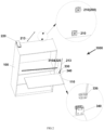
- cabinet lighting power-taking system 1000 which is suitable for but is not limited to storage cabinets such as LED cabinets or article display cabinets.
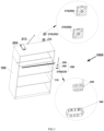
- the cabinet lighting power-taking system 1000 includes a cabinet 100, a power-taking assembly 200, and lamps 300.
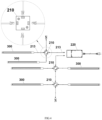
- the power-taking assembly 200 includes at least one wire-distribution box 210, which is installed on a surface of the cabinet 100 and is provided with a power-input interface and a plurality of power-output interface for splitting a single power-output interface into the plurality of power-output interfaces in parallel through shunt conversion.
- the power-input interface is configured for receiving commercial power.
- a plurality of lamps 300 are installed in the cabinet 100, and the plurality of lamps 300 are plugged one to one with the plurality of power-output interfaces.
- the cabinet body 100 may be made of wood board, plastic board, glass board, aluminum alloy board or stainless steel board, etc, which is not limited here.
- a main body of the wire-distribution box 210 of the power-taking assembly 200 may have a square structure or other shapes, and may be made of non-conductive materials.
- the plurality of power-output interface for receiving connection terminals of terminal connecting wires 213 of the lamps 300 may be arranged on a periphery of the main body, in order to connect the lamp 300 to the commercial power.
- the lamps 300 are installed inside the cabinet 100 and can be connected to the power-output interfaces on the wire-distribution box 210 on the back board of the cabinet 100 through the terminal connecting wires 213 from the lamps 300.
- a lamp body 310 of each lamp 300 may be constituted by a COB lamp band with LED beads (COB, Chip On Board) or a FPC lamp band (FPC, Flexible Printed Circuit) and the like, and a shell, the lamp body 310 may be in the form of a strip, a circle or other shapes, and is not limited here.
- the wire-distribution box 210 can be installed on the back of the cabinet 100 by means of screw connection or glue bonding, etc., and then the lamps 300 can be installed on a shelf 110 or a side board in the cabinet 100, and the terminal connecting wires 213 from the lamps 300 can be connected to the power-output interfaces on the wire-distribution box 210.
- the assembly of the whole cabinet lighting power-taking system 1000 is completed, the whole assembly process is simple and convenient.
- users may replace a new lamp 300 by themselves. The operation is simple, and the user experience is improved.
- the power-taking assembly 200 includes at least one wire-distribution box 210, which is attached to the surface of the cabinet 100 and is provided with a power-input interface and a plurality of power-output interfaces, so as to distribute a single power-output interface into a plurality of power-output interfaces in parallel through shunt conversion.
- the power-input interface is configured for connecting commercial power
- the plurality of lamps 300 are installed in the cabinet 100, and the plurality of lamps 300 are plugged into the plurality of power-output interfaces one to one, thus improving the assembly convenience of the lighting power-taking system 1000 in the cabinet.
- the power-taking assembly 200 may further include a power supply driver 220 for providing an operating voltage, and the power-input interface of the wire-distribution box 210 is connected to the commercial power through the power supply driver 220.
- the power supply driver 220 in this embodiment is arranged to convert the mains voltage into the operating voltage of the lamps 300.
- each lamp 300 may include a lamp body 310, a first lamp holder 320 and a second lamp holder 330 that is inserted in the first lamp holder 320 and electrically connected to the first lamp holder 320.
- the first lamp holder 320 is disposed on the lamp body 310, and the second lamp holder 330 is installed in the cabinet 100 and electrically connected to a power-output interface of the wire-distribution box 210 through a terminal connecting wire 213.
- the second lamp holder 330 and the wire-distribution box of the power-taking assembly 200 are connected through the terminal connecting wire 213.
- the terminal connecting wire 213 is generally extended from the second lamp holder 330.
- An outgoing terminal of the terminal connecting wire 213 is electrically connected with a power-output interface of the wire-distribution box 210 by plugging in to facilitate wiring.
- the first lamp holder 320 and the second lamp holder 330 can be adsorbed and fixed by magnets.
- an engagement structure or the like may be provided at joints of the terminal connecting wire 213 of the second lamp holder 330 and the power-output interface of the wire-distribution box 210 for inserting and pulling out the terminal connecting wire 213.
- the cabinet 100 includes a back board, a plurality of side boards arranged around the back board and a plurality of shelves 110.
- the back board and the plurality of side boards are enclosed to form a cuboid-shaped structure with a cabinet opening.
- the plurality of shelves 110 are spaced along a height direction of the cabinet 100 between two lateral opposite side boards and are attached to the back board.
- the lamps 300 are installed on the shelves 110 to obtain a better light irradiation range.
- the lamps 300 of the present embodiment may be installed on the front side (front shelf lamp), or the rear side (rear shelf lamp) of the shelves 110 or embedded in the shelf 110 (embedded profile light).
- front side front shelf lamp
- rear side rear shelf lamp
- embedded profile light embedded profile light
- a wire hole is formed at a position corresponding to each lamp 300 on the back board through which the terminal connecting wire 213 connecting the second lamp holder 330 and the power-output interface of the wire-distribution box 210 passes.
- the lamp 300 may further include an installing member 340, which is disposed in the cabinet 100, and the second lamp holder 330 is installed in the cabinet 100 through the installing member 340.
- the shelf 110 may be provided with an embedded groove, and the installing member 340 is arranged in the embedded groove.
- the installing member 340 can be flush with a surface of the cabinet body 100 as far as possible, and the lighting power-taking system 1000 in the cabinet may also enhance a certain industrial aesthetic feeling.
- the cabinet lighting power-taking system 1000 may further include a controller (not shown) through which the wire-distribution box 210 is connected to the lamps 300.
- the controller is configured to control the luminous color temperature or brightness of the lamps 300 and to control the opening or closing of the lamps 300.
- the brightness, color temperature and continuous flashing time of the lamps 300 need to be adjusted to meet various lighting requirements of users.
- the controller in this embodiment can adjust the luminous color of the lamps 300 according to a preset program of a system, for example, in a first preset time range, the lamps 300 are controlled to emit red light, in a second preset time range, the lamps 300 are controlled to emit yellow light, in a third preset time range, the lamps 300 are controlled to emit white light, and in a fourth preset time, the lamps 300 are controlled to be powered off to stop emitting light, and the like.
- the specific control method of the controller is not limited here.
Landscapes
- Engineering & Computer Science (AREA)
- General Engineering & Computer Science (AREA)
- Power Engineering (AREA)
- Microelectronics & Electronic Packaging (AREA)
- Architecture (AREA)
- Civil Engineering (AREA)
- Structural Engineering (AREA)
- Arrangement Of Elements, Cooling, Sealing, Or The Like Of Lighting Devices (AREA)
- Non-Portable Lighting Devices Or Systems Thereof (AREA)
Claims (4)
- Système de prise de puissance et d'éclairage pour une armoire (1000), comprenant un corps d'armoire (100) et une pluralité de lampes (300) installées dans le corps d'armoire (100) ;un ensemble de prise de puissance (200) comprenant au moins un boîtier de distribution de fils (210), dans lequel au moins un boîtier de distribution de fils (210) est installé sur le corps d'armoire (100) et pourvu d'une interface d'entrée de puissance et d'une pluralité d'interfaces de sortie de puissance pour séparer une seule interface de sortie de puissance en une pluralité d'interfaces de sortie de puissance en parallèle par conversion shunt, et l'interface d'entrée de puissance est configurée pour connecter une source d'alimentation commerciale ; etla pluralité des lampes (300) sont connectées à la pluralité d'interfaces de sortie de puissance de manière de correspondance biunivoque ; caractérisé en ce que,chaque lampe (300) comprend un corps de lampe (310), un premier support de lampe (320) et un deuxième support de lampe (330) inséré dans le premier support de lampe (320), dans lequel le premier support de lampe (320) est connecté électriquement au deuxième support de lampe (330), le premier support de lampe (320) est configuré sur le corps de lampe (310) et le deuxième support de lampe (330) est installé dans le corps d'armoire (100) et connecté électriquement à l'interface de sortie de puissance du boîtier de distribution de fils (210) ;le premier support de lampe (320) et le deuxième support de lampe (330) sont fixés par l'attraction d'un aimant ;le corps d'armoire (100) comprend une planche arrière, une pluralité de planches latérales disposées autour de la planche arrière et une pluralité de cloisons (110), dans lequel la planche arrière et la pluralité de planches latérales sont fermées pour former une structure cuboïde ayant une ouverture d'armoire, et la pluralité de cloisons (110) sont disposées à intervalles entre deux planches latérales transversalement opposées le long d'une direction de hauteur du corps d'armoire (100) et sont fixées à la planche arrière ;la planche arrière est pourvue d'un trou métallique à travers lequel passe un fil de connexion à borne connectant le deuxième support de lampe (330) et l'interface de sortie de puissance du boîtier de distribution de fils (210) à une position correspondant à la lampe (300) ;l'un de la pluralité de lampes (300) comprend en outre un élément d'installation, l'élément d'installation est configuré dans le corps d'armoire (100) et le deuxième support de lampe (330) est configuré dans le corps d'armoire (100) par l'intermédiaire de l'élément d'installation ; etl'une de la pluralité de cloisons (110) est pourvue d'une rainure d'encastrement et l'élément d'installation est disposé dans la rainure d'encastrement.
- Système de prise de puissance et d'éclairage pour une armoire (1000) selon la revendication 1, dans lequel l'ensemble de prise de puissance (200) comprend en outre un entraîneur de source d'alimentation, et l'interface d'entrée de puissance du boîtier de distribution de fils (210) est connectée à la source d'alimentation commerciale par l'intermédiaire de l'entraîneur de source d'alimentation ; l'entraîneur de source d'alimentation est configuré pour convertir une tension de la source d'alimentation en tension de fonctionnement.
- Système de prise de puissance et d'éclairage pour une armoire (1000) selon la revendication 2, dans lequel chaque lampe (300) est installée sur la cloison (110) ou sur les planches latérales.
- Système de prise de puissance et d'éclairage pour une armoire (1000) selon la revendication 1, comprenant en outre un contrôleur, dans lequel, le contrôleur est connecté entre le boîtier de distribution de fils (210) et la lampe (300) ; le contrôleur est configuré pour contrôler les températures de couleur lumineuse ou la luminosité des lampes et contrôler l'allumage ou l'extinction de la pluralité de lampes.
Applications Claiming Priority (1)
| Application Number | Priority Date | Filing Date | Title |
|---|---|---|---|
| CN202010944531.1A CN111911848A (zh) | 2020-09-09 | 2020-09-09 | 柜内灯光照明取电系统 |
Publications (2)
| Publication Number | Publication Date |
|---|---|
| EP3968736A1 EP3968736A1 (fr) | 2022-03-16 |
| EP3968736B1 true EP3968736B1 (fr) | 2023-10-25 |
Family
ID=73267575
Family Applications (1)
| Application Number | Title | Priority Date | Filing Date |
|---|---|---|---|
| EP21166025.3A Active EP3968736B1 (fr) | 2020-09-09 | 2021-03-30 | Système de prise de courant d'éclairage d'armoire |
Country Status (4)
| Country | Link |
|---|---|
| US (1) | US11384926B2 (fr) |
| EP (1) | EP3968736B1 (fr) |
| CN (1) | CN111911848A (fr) |
| PL (1) | PL3968736T3 (fr) |
Families Citing this family (1)
| Publication number | Priority date | Publication date | Assignee | Title |
|---|---|---|---|---|
| US20250360428A1 (en) * | 2024-05-22 | 2025-11-27 | Killian Patton | Modular display system |
Family Cites Families (12)
| Publication number | Priority date | Publication date | Assignee | Title |
|---|---|---|---|---|
| US5559681A (en) * | 1994-05-13 | 1996-09-24 | Cnc Automation, Inc. | Flexible, self-adhesive, modular lighting system |
| US5580155A (en) * | 1994-11-03 | 1996-12-03 | Jeff Hildebrand | Cabinet lighting system |
| US5893627A (en) | 1996-02-16 | 1999-04-13 | James W. Tague | Automatic low voltage lighting system for cabinets and closets |
| US7445353B2 (en) | 2000-08-29 | 2008-11-04 | Ole K. Nilssen | Distributed lighting system |
| US7367685B2 (en) * | 2005-02-25 | 2008-05-06 | Nexlite | Lighted cabinet assembly |
| US8746908B2 (en) * | 2010-01-27 | 2014-06-10 | Automed Technologies, Inc. | Medical supply cabinet with lighting features |
| CN106678627A (zh) * | 2017-03-27 | 2017-05-17 | 昆山百亨光电科技有限公司 | Led橱柜灯 |
| US10539309B2 (en) | 2017-11-22 | 2020-01-21 | Amax Incorporated | Low voltage LED under cabinet light bar |
| US10401018B1 (en) * | 2018-03-16 | 2019-09-03 | Hafele America Co. | Illuminated cabinet |
| CN211372033U (zh) * | 2019-11-19 | 2020-08-28 | 漳州立达信光电子科技有限公司 | 系统化橱柜灯 |
| CN111609349A (zh) * | 2020-06-23 | 2020-09-01 | 温州市益立艺术家居有限公司 | 一种柜架中隐藏灯条取电装置及其柜架 |
| CN212805312U (zh) * | 2020-09-09 | 2021-03-26 | 深圳市捷德韦尔智能光电有限公司 | 柜内灯光照明取电系统 |
-
2020
- 2020-09-09 CN CN202010944531.1A patent/CN111911848A/zh active Pending
-
2021
- 2021-03-30 US US17/216,889 patent/US11384926B2/en active Active
- 2021-03-30 PL PL21166025.3T patent/PL3968736T3/pl unknown
- 2021-03-30 EP EP21166025.3A patent/EP3968736B1/fr active Active
Also Published As
| Publication number | Publication date |
|---|---|
| CN111911848A (zh) | 2020-11-10 |
| EP3968736A1 (fr) | 2022-03-16 |
| US11384926B2 (en) | 2022-07-12 |
| PL3968736T3 (pl) | 2024-02-26 |
| US20220074579A1 (en) | 2022-03-10 |
Similar Documents
| Publication | Publication Date | Title |
|---|---|---|
| US10588187B2 (en) | LED driver adapted for gang boxes | |
| US9167660B2 (en) | Combined surface mount and in-wall mount dimmer | |
| US9039230B2 (en) | Apparatus, system, and method for track lighting | |
| US10851988B2 (en) | Integrated lighting and power for cabinetry | |
| CN104315393B (zh) | 一种易组装的模块化led灯具 | |
| US20140301073A1 (en) | Linear led lighting device, system, method, and apparatus | |
| US20150362164A1 (en) | Lighting Power Supply System | |
| MX2015003395A (es) | Sistema de barras de distribucion de bajo voltaje. | |
| US12584621B2 (en) | Connector for integrated lighting and power for cabinetry | |
| CN204693228U (zh) | 色温可调的音乐吸顶灯 | |
| CN102798021B (zh) | 一种led灯及驱动开关 | |
| US11384926B2 (en) | Cabinet lighting power-taking system | |
| US12163650B2 (en) | Integrated lighting and power for cabinetry and connectors for same | |
| CN103867990B (zh) | 一种路灯 | |
| CN212805312U (zh) | 柜内灯光照明取电系统 | |
| CN209593842U (zh) | 灯具控制系统及照明系统 | |
| CN210197056U (zh) | 一种模块化橱柜灯 | |
| CN206176147U (zh) | Led平板灯 | |
| CN223957685U (zh) | 一种柜内灯控制系统 | |
| JP2016058171A (ja) | Led照明器具 | |
| CN203595086U (zh) | Led灯具 | |
| CN223375725U (zh) | 一种柜内灯布线系统 | |
| CN204611559U (zh) | 色温可调的音乐吸顶灯 | |
| CN217160220U (zh) | 四路独立分控器 | |
| US20260110411A1 (en) | Modular linear lighting system and methods for assembling same |
Legal Events
| Date | Code | Title | Description |
|---|---|---|---|
| PUAI | Public reference made under article 153(3) epc to a published international application that has entered the european phase |
Free format text: ORIGINAL CODE: 0009012 |
|
| STAA | Information on the status of an ep patent application or granted ep patent |
Free format text: STATUS: THE APPLICATION HAS BEEN PUBLISHED |
|
| AK | Designated contracting states |
Kind code of ref document: A1 Designated state(s): AL AT BE BG CH CY CZ DE DK EE ES FI FR GB GR HR HU IE IS IT LI LT LU LV MC MK MT NL NO PL PT RO RS SE SI SK SM TR |
|
| STAA | Information on the status of an ep patent application or granted ep patent |
Free format text: STATUS: REQUEST FOR EXAMINATION WAS MADE |
|
| 17P | Request for examination filed |
Effective date: 20220719 |
|
| RBV | Designated contracting states (corrected) |
Designated state(s): AL AT BE BG CH CY CZ DE DK EE ES FI FR GB GR HR HU IE IS IT LI LT LU LV MC MK MT NL NO PL PT RO RS SE SI SK SM TR |
|
| GRAP | Despatch of communication of intention to grant a patent |
Free format text: ORIGINAL CODE: EPIDOSNIGR1 |
|
| STAA | Information on the status of an ep patent application or granted ep patent |
Free format text: STATUS: GRANT OF PATENT IS INTENDED |
|
| RIC1 | Information provided on ipc code assigned before grant |
Ipc: A47F 3/00 20060101ALI20230523BHEP Ipc: H05B 45/10 20200101ALI20230523BHEP Ipc: H05B 45/20 20200101ALI20230523BHEP Ipc: F21W 131/301 20060101ALI20230523BHEP Ipc: F21V 23/02 20060101ALI20230523BHEP Ipc: H05B 47/10 20200101AFI20230523BHEP |
|
| INTG | Intention to grant announced |
Effective date: 20230613 |
|
| GRAS | Grant fee paid |
Free format text: ORIGINAL CODE: EPIDOSNIGR3 |
|
| GRAA | (expected) grant |
Free format text: ORIGINAL CODE: 0009210 |
|
| STAA | Information on the status of an ep patent application or granted ep patent |
Free format text: STATUS: THE PATENT HAS BEEN GRANTED |
|
| AK | Designated contracting states |
Kind code of ref document: B1 Designated state(s): AL AT BE BG CH CY CZ DE DK EE ES FI FR GB GR HR HU IE IS IT LI LT LU LV MC MK MT NL NO PL PT RO RS SE SI SK SM TR |
|
| REG | Reference to a national code |
Ref country code: GB Ref legal event code: FG4D |
|
| REG | Reference to a national code |
Ref country code: CH Ref legal event code: EP |
|
| REG | Reference to a national code |
Ref country code: DE Ref legal event code: R096 Ref document number: 602021006108 Country of ref document: DE |
|
| REG | Reference to a national code |
Ref country code: IE Ref legal event code: FG4D |
|
| REG | Reference to a national code |
Ref country code: LT Ref legal event code: MG9D |
|
| REG | Reference to a national code |
Ref country code: NL Ref legal event code: MP Effective date: 20231025 |
|
| REG | Reference to a national code |
Ref country code: AT Ref legal event code: MK05 Ref document number: 1626054 Country of ref document: AT Kind code of ref document: T Effective date: 20231025 |
|
| PG25 | Lapsed in a contracting state [announced via postgrant information from national office to epo] |
Ref country code: NL Free format text: LAPSE BECAUSE OF FAILURE TO SUBMIT A TRANSLATION OF THE DESCRIPTION OR TO PAY THE FEE WITHIN THE PRESCRIBED TIME-LIMIT Effective date: 20231025 |
|
| PG25 | Lapsed in a contracting state [announced via postgrant information from national office to epo] |
Ref country code: GR Free format text: LAPSE BECAUSE OF FAILURE TO SUBMIT A TRANSLATION OF THE DESCRIPTION OR TO PAY THE FEE WITHIN THE PRESCRIBED TIME-LIMIT Effective date: 20240126 |
|
| PG25 | Lapsed in a contracting state [announced via postgrant information from national office to epo] |
Ref country code: IS Free format text: LAPSE BECAUSE OF FAILURE TO SUBMIT A TRANSLATION OF THE DESCRIPTION OR TO PAY THE FEE WITHIN THE PRESCRIBED TIME-LIMIT Effective date: 20240225 |
|
| PG25 | Lapsed in a contracting state [announced via postgrant information from national office to epo] |
Ref country code: LT Free format text: LAPSE BECAUSE OF FAILURE TO SUBMIT A TRANSLATION OF THE DESCRIPTION OR TO PAY THE FEE WITHIN THE PRESCRIBED TIME-LIMIT Effective date: 20231025 |
|
| PG25 | Lapsed in a contracting state [announced via postgrant information from national office to epo] |
Ref country code: AT Free format text: LAPSE BECAUSE OF FAILURE TO SUBMIT A TRANSLATION OF THE DESCRIPTION OR TO PAY THE FEE WITHIN THE PRESCRIBED TIME-LIMIT Effective date: 20231025 |
|
| PG25 | Lapsed in a contracting state [announced via postgrant information from national office to epo] |
Ref country code: ES Free format text: LAPSE BECAUSE OF FAILURE TO SUBMIT A TRANSLATION OF THE DESCRIPTION OR TO PAY THE FEE WITHIN THE PRESCRIBED TIME-LIMIT Effective date: 20231025 |
|
| PG25 | Lapsed in a contracting state [announced via postgrant information from national office to epo] |
Ref country code: LT Free format text: LAPSE BECAUSE OF FAILURE TO SUBMIT A TRANSLATION OF THE DESCRIPTION OR TO PAY THE FEE WITHIN THE PRESCRIBED TIME-LIMIT Effective date: 20231025 Ref country code: IS Free format text: LAPSE BECAUSE OF FAILURE TO SUBMIT A TRANSLATION OF THE DESCRIPTION OR TO PAY THE FEE WITHIN THE PRESCRIBED TIME-LIMIT Effective date: 20240225 Ref country code: GR Free format text: LAPSE BECAUSE OF FAILURE TO SUBMIT A TRANSLATION OF THE DESCRIPTION OR TO PAY THE FEE WITHIN THE PRESCRIBED TIME-LIMIT Effective date: 20240126 Ref country code: ES Free format text: LAPSE BECAUSE OF FAILURE TO SUBMIT A TRANSLATION OF THE DESCRIPTION OR TO PAY THE FEE WITHIN THE PRESCRIBED TIME-LIMIT Effective date: 20231025 Ref country code: BG Free format text: LAPSE BECAUSE OF FAILURE TO SUBMIT A TRANSLATION OF THE DESCRIPTION OR TO PAY THE FEE WITHIN THE PRESCRIBED TIME-LIMIT Effective date: 20240125 Ref country code: AT Free format text: LAPSE BECAUSE OF FAILURE TO SUBMIT A TRANSLATION OF THE DESCRIPTION OR TO PAY THE FEE WITHIN THE PRESCRIBED TIME-LIMIT Effective date: 20231025 Ref country code: PT Free format text: LAPSE BECAUSE OF FAILURE TO SUBMIT A TRANSLATION OF THE DESCRIPTION OR TO PAY THE FEE WITHIN THE PRESCRIBED TIME-LIMIT Effective date: 20240226 |
|
| PG25 | Lapsed in a contracting state [announced via postgrant information from national office to epo] |
Ref country code: SE Free format text: LAPSE BECAUSE OF FAILURE TO SUBMIT A TRANSLATION OF THE DESCRIPTION OR TO PAY THE FEE WITHIN THE PRESCRIBED TIME-LIMIT Effective date: 20231025 Ref country code: RS Free format text: LAPSE BECAUSE OF FAILURE TO SUBMIT A TRANSLATION OF THE DESCRIPTION OR TO PAY THE FEE WITHIN THE PRESCRIBED TIME-LIMIT Effective date: 20231025 Ref country code: NO Free format text: LAPSE BECAUSE OF FAILURE TO SUBMIT A TRANSLATION OF THE DESCRIPTION OR TO PAY THE FEE WITHIN THE PRESCRIBED TIME-LIMIT Effective date: 20240125 Ref country code: LV Free format text: LAPSE BECAUSE OF FAILURE TO SUBMIT A TRANSLATION OF THE DESCRIPTION OR TO PAY THE FEE WITHIN THE PRESCRIBED TIME-LIMIT Effective date: 20231025 Ref country code: HR Free format text: LAPSE BECAUSE OF FAILURE TO SUBMIT A TRANSLATION OF THE DESCRIPTION OR TO PAY THE FEE WITHIN THE PRESCRIBED TIME-LIMIT Effective date: 20231025 |
|
| PG25 | Lapsed in a contracting state [announced via postgrant information from national office to epo] |
Ref country code: DK Free format text: LAPSE BECAUSE OF FAILURE TO SUBMIT A TRANSLATION OF THE DESCRIPTION OR TO PAY THE FEE WITHIN THE PRESCRIBED TIME-LIMIT Effective date: 20231025 |
|
| PG25 | Lapsed in a contracting state [announced via postgrant information from national office to epo] |
Ref country code: CZ Free format text: LAPSE BECAUSE OF FAILURE TO SUBMIT A TRANSLATION OF THE DESCRIPTION OR TO PAY THE FEE WITHIN THE PRESCRIBED TIME-LIMIT Effective date: 20231025 |
|
| REG | Reference to a national code |
Ref country code: DE Ref legal event code: R097 Ref document number: 602021006108 Country of ref document: DE |
|
| PG25 | Lapsed in a contracting state [announced via postgrant information from national office to epo] |
Ref country code: SK Free format text: LAPSE BECAUSE OF FAILURE TO SUBMIT A TRANSLATION OF THE DESCRIPTION OR TO PAY THE FEE WITHIN THE PRESCRIBED TIME-LIMIT Effective date: 20231025 |
|
| PG25 | Lapsed in a contracting state [announced via postgrant information from national office to epo] |
Ref country code: SM Free format text: LAPSE BECAUSE OF FAILURE TO SUBMIT A TRANSLATION OF THE DESCRIPTION OR TO PAY THE FEE WITHIN THE PRESCRIBED TIME-LIMIT Effective date: 20231025 Ref country code: SK Free format text: LAPSE BECAUSE OF FAILURE TO SUBMIT A TRANSLATION OF THE DESCRIPTION OR TO PAY THE FEE WITHIN THE PRESCRIBED TIME-LIMIT Effective date: 20231025 Ref country code: RO Free format text: LAPSE BECAUSE OF FAILURE TO SUBMIT A TRANSLATION OF THE DESCRIPTION OR TO PAY THE FEE WITHIN THE PRESCRIBED TIME-LIMIT Effective date: 20231025 Ref country code: IT Free format text: LAPSE BECAUSE OF FAILURE TO SUBMIT A TRANSLATION OF THE DESCRIPTION OR TO PAY THE FEE WITHIN THE PRESCRIBED TIME-LIMIT Effective date: 20231025 Ref country code: EE Free format text: LAPSE BECAUSE OF FAILURE TO SUBMIT A TRANSLATION OF THE DESCRIPTION OR TO PAY THE FEE WITHIN THE PRESCRIBED TIME-LIMIT Effective date: 20231025 Ref country code: DK Free format text: LAPSE BECAUSE OF FAILURE TO SUBMIT A TRANSLATION OF THE DESCRIPTION OR TO PAY THE FEE WITHIN THE PRESCRIBED TIME-LIMIT Effective date: 20231025 Ref country code: CZ Free format text: LAPSE BECAUSE OF FAILURE TO SUBMIT A TRANSLATION OF THE DESCRIPTION OR TO PAY THE FEE WITHIN THE PRESCRIBED TIME-LIMIT Effective date: 20231025 |
|
| PLBE | No opposition filed within time limit |
Free format text: ORIGINAL CODE: 0009261 |
|
| STAA | Information on the status of an ep patent application or granted ep patent |
Free format text: STATUS: NO OPPOSITION FILED WITHIN TIME LIMIT |
|
| 26N | No opposition filed |
Effective date: 20240726 |
|
| PG25 | Lapsed in a contracting state [announced via postgrant information from national office to epo] |
Ref country code: SI Free format text: LAPSE BECAUSE OF FAILURE TO SUBMIT A TRANSLATION OF THE DESCRIPTION OR TO PAY THE FEE WITHIN THE PRESCRIBED TIME-LIMIT Effective date: 20231025 |
|
| PG25 | Lapsed in a contracting state [announced via postgrant information from national office to epo] |
Ref country code: SI Free format text: LAPSE BECAUSE OF FAILURE TO SUBMIT A TRANSLATION OF THE DESCRIPTION OR TO PAY THE FEE WITHIN THE PRESCRIBED TIME-LIMIT Effective date: 20231025 |
|
| REG | Reference to a national code |
Ref country code: CH Ref legal event code: PL |
|
| PG25 | Lapsed in a contracting state [announced via postgrant information from national office to epo] |
Ref country code: LU Free format text: LAPSE BECAUSE OF NON-PAYMENT OF DUE FEES Effective date: 20240330 |
|
| PG25 | Lapsed in a contracting state [announced via postgrant information from national office to epo] |
Ref country code: MC Free format text: LAPSE BECAUSE OF FAILURE TO SUBMIT A TRANSLATION OF THE DESCRIPTION OR TO PAY THE FEE WITHIN THE PRESCRIBED TIME-LIMIT Effective date: 20231025 |
|
| PG25 | Lapsed in a contracting state [announced via postgrant information from national office to epo] |
Ref country code: MC Free format text: LAPSE BECAUSE OF FAILURE TO SUBMIT A TRANSLATION OF THE DESCRIPTION OR TO PAY THE FEE WITHIN THE PRESCRIBED TIME-LIMIT Effective date: 20231025 Ref country code: LU Free format text: LAPSE BECAUSE OF NON-PAYMENT OF DUE FEES Effective date: 20240330 |
|
| REG | Reference to a national code |
Ref country code: BE Ref legal event code: MM Effective date: 20240331 |
|
| PG25 | Lapsed in a contracting state [announced via postgrant information from national office to epo] |
Ref country code: BE Free format text: LAPSE BECAUSE OF NON-PAYMENT OF DUE FEES Effective date: 20240331 |
|
| PG25 | Lapsed in a contracting state [announced via postgrant information from national office to epo] |
Ref country code: IE Free format text: LAPSE BECAUSE OF NON-PAYMENT OF DUE FEES Effective date: 20240330 |
|
| PG25 | Lapsed in a contracting state [announced via postgrant information from national office to epo] |
Ref country code: IE Free format text: LAPSE BECAUSE OF NON-PAYMENT OF DUE FEES Effective date: 20240330 Ref country code: BE Free format text: LAPSE BECAUSE OF NON-PAYMENT OF DUE FEES Effective date: 20240331 Ref country code: CH Free format text: LAPSE BECAUSE OF NON-PAYMENT OF DUE FEES Effective date: 20240331 |
|
| PGFP | Annual fee paid to national office [announced via postgrant information from national office to epo] |
Ref country code: FR Payment date: 20250331 Year of fee payment: 5 Ref country code: PL Payment date: 20250318 Year of fee payment: 5 |
|
| PGFP | Annual fee paid to national office [announced via postgrant information from national office to epo] |
Ref country code: DE Payment date: 20250411 Year of fee payment: 5 |
|
| PG25 | Lapsed in a contracting state [announced via postgrant information from national office to epo] |
Ref country code: CY Free format text: LAPSE BECAUSE OF FAILURE TO SUBMIT A TRANSLATION OF THE DESCRIPTION OR TO PAY THE FEE WITHIN THE PRESCRIBED TIME-LIMIT; INVALID AB INITIO Effective date: 20210330 |
|
| PG25 | Lapsed in a contracting state [announced via postgrant information from national office to epo] |
Ref country code: HU Free format text: LAPSE BECAUSE OF FAILURE TO SUBMIT A TRANSLATION OF THE DESCRIPTION OR TO PAY THE FEE WITHIN THE PRESCRIBED TIME-LIMIT; INVALID AB INITIO Effective date: 20210330 |
|
| PG25 | Lapsed in a contracting state [announced via postgrant information from national office to epo] |
Ref country code: FI Free format text: LAPSE BECAUSE OF FAILURE TO SUBMIT A TRANSLATION OF THE DESCRIPTION OR TO PAY THE FEE WITHIN THE PRESCRIBED TIME-LIMIT Effective date: 20231025 |
|
| GBPC | Gb: european patent ceased through non-payment of renewal fee |
Effective date: 20250330 |
|
| PG25 | Lapsed in a contracting state [announced via postgrant information from national office to epo] |
Ref country code: TR Free format text: LAPSE BECAUSE OF FAILURE TO SUBMIT A TRANSLATION OF THE DESCRIPTION OR TO PAY THE FEE WITHIN THE PRESCRIBED TIME-LIMIT Effective date: 20231025 |
|
| PG25 | Lapsed in a contracting state [announced via postgrant information from national office to epo] |
Ref country code: GB Free format text: LAPSE BECAUSE OF NON-PAYMENT OF DUE FEES Effective date: 20250330 |