EP3969663B1 - Passierbare dehnungsfuge - Google Patents
Passierbare dehnungsfuge Download PDFInfo
- Publication number
- EP3969663B1 EP3969663B1 EP20724148.0A EP20724148A EP3969663B1 EP 3969663 B1 EP3969663 B1 EP 3969663B1 EP 20724148 A EP20724148 A EP 20724148A EP 3969663 B1 EP3969663 B1 EP 3969663B1
- Authority
- EP
- European Patent Office
- Prior art keywords
- groove
- threaded elements
- joint according
- threaded
- profiled
- Prior art date
- Legal status (The legal status is an assumption and is not a legal conclusion. Google has not performed a legal analysis and makes no representation as to the accuracy of the status listed.)
- Active
Links
Images


Classifications
-
- E—FIXED CONSTRUCTIONS
- E01—CONSTRUCTION OF ROADS, RAILWAYS, OR BRIDGES
- E01D—CONSTRUCTION OF BRIDGES, ELEVATED ROADWAYS OR VIADUCTS; ASSEMBLY OF BRIDGES
- E01D19/00—Structural or constructional details of bridges
- E01D19/06—Arrangement, construction or bridging of expansion joints
Definitions
- the present invention relates to civil engineering equipment and more specifically to expansion joints.
- Driveable expansion joints are used to connect two portions of road surface that are likely to undergo relative movements. These joints are arranged in such a way as to fill the gaps extending between the portions of road surface concerned, thus ensuring the continuity of the rolling.
- Expansion joints typically consist of metal toothed plates fixed to profiles.
- the request DE 4433909A teaches to fix these toothed plates with screws. However, being exposed to vibrations caused by the passage of vehicles, these may loosen during use.
- the patent KR 100 726 379 B1 discloses a driveable expansion joint according to the preamble of claim 1.
- One of the aims of the invention is thus to propose an expansion joint which is reliable in use and easy to maintain.
- the invention aims to achieve this objective and it achieves it by means of a drive-over expansion joint according to claim 1.
- the seal according to the invention comprises a sealing gasket received in a groove in the profile.
- locking washers make it possible to keep the threaded elements locked in rotation after they have been tightened. These locking washers maintain a pre-stressing force in the threaded elements for a long time. Thus, the invention reduces the risk of unwanted loosening of the threaded elements, which is a source of vibration and noise.
- toothed plates are held by threaded elements on the profiles allows relatively quick and easy maintenance of the expansion joint.
- the replacement of certain component parts, such as the sealing gaskets, is therefore made easier.
- the threaded elements are engaged in holes in the profile opening into said groove, which makes it possible to maximize the grip length of the screws.
- the threaded elements come into contact with the sealing gasket.
- the surface of the groove into which the bores open is concave toward the inside of the groove, and the threaded elements have a length such that their end extends at least partially out of the bore into the groove.
- the profile may be an edge profile comprising a single groove for receiving the sealing gasket.
- the profile may also be an intermediate profile comprising two grooves, open in opposite directions, for receiving respective sealing gaskets.
- This profile may have holes which open into the grooves. The holes opening into one of the grooves may be offset along the longitudinal axis of the profile relative to the holes opening into the other groove.
- the holes opening into one of the grooves occupy the same position along the longitudinal axis of the profile as the holes opening into the other groove, the threaded elements being engaged alternately in the holes associated with said grooves. This can allow the toothed plates to be mounted in two inverse configurations on the intermediate profile.
- the or each groove may have a flanged edge delimiting its opening at the top; the holes for receiving the threaded elements may open behind this flanged edge.
- the threaded elements may be headed screws or nuts, and are preferably headed screws.
- the joint may comprise at least two toothed rolling plates arranged in line with one another, preferably with one of the plates overlapping the other longitudinally; each of the plates may have at least one end tooth, the bases of the end teeth of the two toothed plates coming into contact.
- Lock washers may be elastic, so that they can be deformed flat, forming a spring between the threaded elements and the bottom of the counterbores. This allows the desired pre-stress to be introduced into the threaded elements.
- the locking washers may be cam-action. Such locking washers are for example described in the application US20180023614 and are marketed by the company NORD LOCK under the name “Nord Lock Washer X”.
- the locking washers each comprise two notched crowns, at least one of which is elastic, preferably both are elastic, the crowns being provided on their facing faces with notches arranged such that a relative rotation of the crowns in the direction of unscrewing of the threaded element is accompanied, by cam effect, by a separation of the crowns opposing the unscrewing.
- the crowns may each have a substantially truncated cone shape at rest.
- the notches exerting the cam effect are preferably inclined at an angle, relative to a transverse plane of the locking washer perpendicular to the axis of the threaded element, greater than that of the helix angle of the threaded element.
- This joint 1 comprises a set of profiles 100 intended to connect two portions of road surface (not illustrated).
- the joint 1 thus comprises two edge profiles 120 and several intermediate profiles 140 arranged between the edge profiles 120.
- the joint 1 comprises several toothed bearing plates 200, fixed by threaded elements 300 on the profiles 120 and 140.
- the rolling plates 200 each have a plurality of teeth 250 extending toward an adjacent plate 200.
- the teeth 250 of two adjacent plates 200 are arranged so as to interlock, when the two plates approach each other.
- Each bearing plate 200 has holes 245 provided with counterbores 265 in which the threaded elements 300 are received.
- toothed rolling plates 200 can be arranged in line with each other.
- Two successive plates 200 preferably have a longitudinal overlap, as visible in the figure 2 . This overlap can be done such that the bases 255 of the end teeth come into mutual contact.
- the threaded elements 300 are screws each provided with a head 310 and a threaded shank 315.
- Locking washers 350 are interposed axially between the threaded elements 300 and the bottom of the counterbores 265, thereby preventing loosening of the threaded elements 300.
- the locking washers are elastically deformable, so as to be able to be deformed flat and form a spring between the threaded elements 300 and the bottom of the counterbores 265.
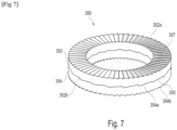
- each locking washer 350 has two toothed crowns 352 and 354 which overlap and come into contact.
- Crowns 352 and 354 have external faces 352a and 354b which rest against threaded member 300 and counterbore 265, respectively.
- crowns 352 and 354 are provided, on their facing faces 352b and 354a, with notches 355 arranged such that a relative rotation of the crowns 322 and 324 in the direction of unscrewing the threaded element 300 is accompanied, by cam effect, by a separation of the crowns opposing the unscrewing.
- the notches 355 are inclined at an angle ⁇ , relative to a transverse plane P of the washer 350, greater than that of the helix angle ⁇ of the thread, which causes positive and effective locking of the threaded element.
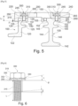
- the edge profiles 120 each comprise a sole 122 having the general shape of an L-shaped angle iron, as can be seen in the figure 5 in particular.
- Each edge profile 120 has a groove 150 intended to receive a sealing gasket (not shown). This groove 150 has a fallen edge 157 delimiting its opening at the top.
- the profile 120 has a rib 125 which delimits the groove 150 at the bottom.
- the profiles 120 and 140 have holes 155 which open into the grooves 150.
- Each groove 150 has an internal surface 152, onto which the holes 155 open, concave towards the inside of the groove 150.
- the threaded elements 300 have a length L such that their end 301 extends at least partially outside the bore 155 inside the groove 150.
- the threaded element 300 can extend outside the bore 155 into the groove 150 by a distance ⁇ greater than or equal to 2 mm, and thus come into contact with the sealing gasket located there.
- the intermediate profiles 140 each comprise a sole 142 having the general shape of an inverted T.
- Each intermediate profile 140 has two grooves 150, open in opposite directions, in which the sealing gaskets are received. Drillings 155 open inside these grooves 150, in a similar manner to what has been described for the edge profiles 120.
- the holes 155 opening into one of the grooves 150 are offset, along the longitudinal axis of the profile 140, relative to the holes opening into the other groove 150.
- the holes 155 opening into one of the grooves 150 occupy the same position, along the longitudinal axis of the profile, as the holes 155 opening into the other groove 150, as illustrated in figure 5 .
- the threaded elements 300 can be engaged alternately in the holes 155.
- head screws can be replaced with threaded rods and nuts.
Landscapes
- Engineering & Computer Science (AREA)
- Architecture (AREA)
- Civil Engineering (AREA)
- Structural Engineering (AREA)
- Gasket Seals (AREA)
- Connection Of Plates (AREA)
Claims (9)
- Passierbare Dehnungsfuge (1), umfassend:- mindestens ein Fugenprofil (100),- mindestens eine gezahnte Fahrbahnplatte (200), wobei diese Platte Bohrungen (245) aufweist, die über Senkungen (265) verfügen,- Gewindeelemente (300) zur Befestigung der Fahrbahnplatte auf dem Profil,- Sicherungsscheiben (350), die zwischen die Gewindeelemente (300) und den Boden der Senkungen (265) axial eingefügt sind, um einer Lockerung der Gewindeelemente (300) entgegenzuwirken, dadurch gekennzeichnet, dass die Sicherungsscheiben (350) eine Keilwirkung aufweisen,- wobei eine Dichtung in einer Nut (150) des Profils (100) aufgenommen ist, wobei die Gewindeelemente (300) in Bohrungen (155) des Profils (100) eingeführt sind, die in der Nut (150) münden, wobei die Oberfläche (152) der Nut (150), an der die Bohrungen (155) münden, zum Inneren der Nut (150) hin konkav ist, wobei die Gewindeelemente (300) eine solche Länge (L) aufweisen, dass sich ihr Ende (301) mindestens teilweise aus der Bohrung (105) heraus in das Innere der Nut (150) erstreckt, wobei die Gewindeelemente mit der Dichtung in Kontakt kommen.
- Fuge nach Anspruch 1, wobei das Profil (100) ein Abschlussprofil (120) ist, das eine einzige Nut (150) zur Aufnahme der Dichtung umfasst.
- Fuge nach Anspruch 1, wobei das Profil (100) ein Zwischenprofil (140) ist, das zwei Nuten (150), die in entgegengesetzten Richtungen offen sind, zur Aufnahme von Dichtungen umfasst, wobei jedes Profil (140) Bohrungen (155) aufweist, die im Inneren der Nuten (150) münden.
- Fuge nach einem der Ansprüche 1 bis 3, wobei die oder jede Nut (150) einen nach unten abgewinkelten Rand (157) umfasst, der ihre Öffnung oben begrenzt, wobei die Bohrung (155) zur Aufnahme der Gewindeelemente (300) hinter diesem nach unten abgewinkelten Rand (157) mündet.
- Fuge nach einem der vorhergehenden Ansprüche, wobei die Gewindeelemente (300) Kopfschrauben (310; 315) sind.
- Fuge nach einem der vorhergehenden Ansprüche, umfassend mindestens zwei gezahnte Fahrbahnplatten (220; 240), die in gegenseitiger Verlängerung angeordnet sind, vorzugsweise mit einer Überlappung in Längsrichtung einer der Platten durch die andere; wobei jede der Platten mindestens einen Endzahn (250) aufweist, wobei die Grundseiten (255) der Endzähne der zwei gezahnten Platten in Kontakt kommen.
- Fuge nach einem der vorhergehenden Ansprüche, wobei die Sicherungsscheiben (350) elastisch sind.
- Fuge nach einem der vorhergehenden Ansprüche, wobei die Sicherungsscheiben jeweils zwei gezackte Kränze (352; 354) umfassen, von denen mindestens einer elastisch ist und vorzugsweise beide elastisch sind, wobei die Kränze (352; 354) auf ihren gegenüberliegenden Flächen (352b; 354a) über Zacken (355) verfügen, die so angeordnet sind, dass eine relative Drehung der Kränze (352; 354) in der Richtung einer Lösung des Gewindeelements (300) aufgrund einer Keilwirkung von einer Spreizung der Kränze (352; 354) begleitet wird, die der Lösung entgegenwirkt.
- Fuge nach Anspruch 8, wobei die Zacken (355) in Bezug auf eine Querebene der Sicherungsscheibe (350), die zu der Achse des Gewindeelements senkrecht ist, um einen Winkel (α) geneigt sind, der größer als der Steigungswinkel (β) des Gewindeelements (300) ist.
Applications Claiming Priority (2)
| Application Number | Priority Date | Filing Date | Title |
|---|---|---|---|
| FR1904931A FR3096060B1 (fr) | 2019-05-13 | 2019-05-13 | Joint de dilatation carrossable |
| PCT/EP2020/063223 WO2020229487A1 (fr) | 2019-05-13 | 2020-05-12 | Joint de dilatation carrossable |
Publications (2)
| Publication Number | Publication Date |
|---|---|
| EP3969663A1 EP3969663A1 (de) | 2022-03-23 |
| EP3969663B1 true EP3969663B1 (de) | 2024-11-20 |
Family
ID=68987729
Family Applications (1)
| Application Number | Title | Priority Date | Filing Date |
|---|---|---|---|
| EP20724148.0A Active EP3969663B1 (de) | 2019-05-13 | 2020-05-12 | Passierbare dehnungsfuge |
Country Status (3)
| Country | Link |
|---|---|
| EP (1) | EP3969663B1 (de) |
| FR (1) | FR3096060B1 (de) |
| WO (1) | WO2020229487A1 (de) |
Families Citing this family (1)
| Publication number | Priority date | Publication date | Assignee | Title |
|---|---|---|---|---|
| CN114935373B (zh) * | 2022-07-25 | 2023-03-17 | 南京大学 | 一种桥梁伸缩缝病害数据模拟采集系统 |
Citations (5)
| Publication number | Priority date | Publication date | Assignee | Title |
|---|---|---|---|---|
| DE2124966A1 (de) | 1971-05-19 | 1972-12-07 | Rheinstahl Ag, 4300 Essen | Fahrbahnübergang für Dehnfugen in Straßen und Gehwegen |
| WO2002027102A1 (de) | 2000-09-26 | 2002-04-04 | Maurer Söhne Gmbh & Co. Kg | Zahnplattenanordnung für eine vorrichtung zum überbrücken von dehnfugen |
| KR100488624B1 (ko) | 2004-04-13 | 2005-05-11 | 주식회사 동아기술공사 | 소음/충격 완화 및 볼트/너트 풀림방지 수단을 구비한신축 이음장치 및 그 시공방법 |
| US20180023614A1 (en) | 2015-02-04 | 2018-01-25 | Nord-Lock Ab | Wedge locking washer with increased corrosion resistance and method for its manufacture |
| DE102017105092A1 (de) | 2017-03-10 | 2018-09-13 | Mageba S.A. | Überbrückungsvorrichtung |
Family Cites Families (2)
| Publication number | Priority date | Publication date | Assignee | Title |
|---|---|---|---|---|
| DE4433909C2 (de) | 1994-09-22 | 1997-11-27 | Alfred Hartkorn | Fugenüberbrückungsvorrichtung |
| KR100726379B1 (ko) * | 2006-02-24 | 2007-06-08 | 주식회사 에스코알티에스 | 교량용 알루미늄 신축이음장치 |
-
2019
- 2019-05-13 FR FR1904931A patent/FR3096060B1/fr active Active
-
2020
- 2020-05-12 EP EP20724148.0A patent/EP3969663B1/de active Active
- 2020-05-12 WO PCT/EP2020/063223 patent/WO2020229487A1/fr not_active Ceased
Patent Citations (5)
| Publication number | Priority date | Publication date | Assignee | Title |
|---|---|---|---|---|
| DE2124966A1 (de) | 1971-05-19 | 1972-12-07 | Rheinstahl Ag, 4300 Essen | Fahrbahnübergang für Dehnfugen in Straßen und Gehwegen |
| WO2002027102A1 (de) | 2000-09-26 | 2002-04-04 | Maurer Söhne Gmbh & Co. Kg | Zahnplattenanordnung für eine vorrichtung zum überbrücken von dehnfugen |
| KR100488624B1 (ko) | 2004-04-13 | 2005-05-11 | 주식회사 동아기술공사 | 소음/충격 완화 및 볼트/너트 풀림방지 수단을 구비한신축 이음장치 및 그 시공방법 |
| US20180023614A1 (en) | 2015-02-04 | 2018-01-25 | Nord-Lock Ab | Wedge locking washer with increased corrosion resistance and method for its manufacture |
| DE102017105092A1 (de) | 2017-03-10 | 2018-09-13 | Mageba S.A. | Überbrückungsvorrichtung |
Non-Patent Citations (2)
| Title |
|---|
| ANONYMOUS: "Talbrücke Albrechtsgraben (Deutschland), Version 2012.09", MAGEBA – PROJEKTINFORMATION, 1 September 2012 (2012-09-01), XP093308802, Retrieved from the Internet <URL:https://www.mageba-group.com/cz/data/docs/de_CZ/2305/Refsheet-Albrechtsgraben-ch-de.pdf> |
| D4: "Brückenbau Construction & Engineering", 2015, VERLAGSGRUPPE WIEDERSPAHN, ISBN: SSN 1867-643X |
Also Published As
| Publication number | Publication date |
|---|---|
| WO2020229487A1 (fr) | 2020-11-19 |
| EP3969663A1 (de) | 2022-03-23 |
| FR3096060B1 (fr) | 2021-06-18 |
| FR3096060A1 (fr) | 2020-11-20 |
Similar Documents
| Publication | Publication Date | Title |
|---|---|---|
| EP1203856B1 (de) | Fugenleiste | |
| EP1481653A1 (de) | Ellenbogengelenkprothese | |
| EP2917969B1 (de) | Vorrichtung zum fixieren einer elektrischen anschlussklemme an einem träger | |
| EP2789888B1 (de) | Spannvorrichtung zum dichten Verbinden von Glattrohren | |
| FR2790046A1 (fr) | Dispositif de fixation de deux panneaux ou analogues forme de deux pieces cooperantes | |
| EP3825594A1 (de) | Schlauchklemme | |
| EP3969663B1 (de) | Passierbare dehnungsfuge | |
| EP2571113B1 (de) | Befestigungs- und Schnellverbindungsvorrichtung für zweiteiligen Anschluss | |
| FR2984431A1 (fr) | Systeme permettant la fixation d'un objet sur un element a rainure(s) de fixation et dispositif de fixation pour un tel systeme | |
| FR2961884A1 (fr) | Collier de serrage a soyage | |
| EP2502806B1 (de) | Zusammenbau einer Fahrzeugbaugruppe und entsprechendes Verfahren | |
| FR2983544A1 (fr) | Rondelle de blocage renforcee | |
| FR3098884A1 (fr) | Collier de serrage à barre de retenue | |
| FR2945329A1 (fr) | Rotor de soufflante d'un turboracteur d'avion | |
| FR2549915A1 (fr) | Perfectionnements aux systemes de vissage comprenant un ecrou a embase et aux composants de ces systemes | |
| FR2948276A1 (fr) | Systeme d'osteosynthese, notamment pour osteosynthese rachidienne | |
| EP2359045B1 (de) | Dichtungsanordnung und zugehörige rohrförmige verbindung | |
| FR2634070A1 (fr) | Connecteur isole pour cables electriques | |
| FR2889773A1 (fr) | Ensemble de rails rigides pour dispositifs d'alimentation electrique par prise mobile de courant | |
| WO2000031846A1 (fr) | Presse-etoupe a garniture d'etancheite et dents de serrage epaisses | |
| FR2828914A1 (fr) | Dispositif d'assemblage | |
| FR2663099A1 (fr) | Support elastique comportant une couche d'elastomere et deux pieces d'extremite, notamment pour moteur marin. | |
| FR2957990A1 (fr) | Rondelle de controle de serrage, ensemble de serrage et collier de prise en charge sur conduite | |
| FR3007495A1 (fr) | Ensemble pour la realisation d'un joint filete pour le forage et l'exploitation des puits d'hydrocarbures, joint filete et procede de realisation d'un tel joint | |
| FR2921703A3 (fr) | Dispositif anti-desserrage d'un ecrou de voie ferree |
Legal Events
| Date | Code | Title | Description |
|---|---|---|---|
| STAA | Information on the status of an ep patent application or granted ep patent |
Free format text: STATUS: UNKNOWN |
|
| STAA | Information on the status of an ep patent application or granted ep patent |
Free format text: STATUS: THE INTERNATIONAL PUBLICATION HAS BEEN MADE |
|
| PUAI | Public reference made under article 153(3) epc to a published international application that has entered the european phase |
Free format text: ORIGINAL CODE: 0009012 |
|
| STAA | Information on the status of an ep patent application or granted ep patent |
Free format text: STATUS: REQUEST FOR EXAMINATION WAS MADE |
|
| 17P | Request for examination filed |
Effective date: 20211213 |
|
| AK | Designated contracting states |
Kind code of ref document: A1 Designated state(s): AL AT BE BG CH CY CZ DE DK EE ES FI FR GB GR HR HU IE IS IT LI LT LU LV MC MK MT NL NO PL PT RO RS SE SI SK SM TR |
|
| RIN1 | Information on inventor provided before grant (corrected) |
Inventor name: MICHOT, ANTHONY Inventor name: SALMON, PHILIPPE |
|
| DAV | Request for validation of the european patent (deleted) | ||
| DAX | Request for extension of the european patent (deleted) | ||
| STAA | Information on the status of an ep patent application or granted ep patent |
Free format text: STATUS: EXAMINATION IS IN PROGRESS |
|
| 17Q | First examination report despatched |
Effective date: 20230613 |
|
| P01 | Opt-out of the competence of the unified patent court (upc) registered |
Effective date: 20230530 |
|
| GRAP | Despatch of communication of intention to grant a patent |
Free format text: ORIGINAL CODE: EPIDOSNIGR1 |
|
| STAA | Information on the status of an ep patent application or granted ep patent |
Free format text: STATUS: GRANT OF PATENT IS INTENDED |
|
| INTG | Intention to grant announced |
Effective date: 20240715 |
|
| GRAS | Grant fee paid |
Free format text: ORIGINAL CODE: EPIDOSNIGR3 |
|
| GRAA | (expected) grant |
Free format text: ORIGINAL CODE: 0009210 |
|
| STAA | Information on the status of an ep patent application or granted ep patent |
Free format text: STATUS: THE PATENT HAS BEEN GRANTED |
|
| AK | Designated contracting states |
Kind code of ref document: B1 Designated state(s): AL AT BE BG CH CY CZ DE DK EE ES FI FR GB GR HR HU IE IS IT LI LT LU LV MC MK MT NL NO PL PT RO RS SE SI SK SM TR |
|
| REG | Reference to a national code |
Ref country code: GB Ref legal event code: FG4D Free format text: NOT ENGLISH |
|
| REG | Reference to a national code |
Ref country code: CH Ref legal event code: EP |
|
| REG | Reference to a national code |
Ref country code: DE Ref legal event code: R096 Ref document number: 602020041643 Country of ref document: DE |
|
| REG | Reference to a national code |
Ref country code: IE Ref legal event code: FG4D Free format text: LANGUAGE OF EP DOCUMENT: FRENCH |
|
| REG | Reference to a national code |
Ref country code: LT Ref legal event code: MG9D |
|
| REG | Reference to a national code |
Ref country code: NL Ref legal event code: MP Effective date: 20241120 |
|
| PG25 | Lapsed in a contracting state [announced via postgrant information from national office to epo] |
Ref country code: PT Free format text: LAPSE BECAUSE OF FAILURE TO SUBMIT A TRANSLATION OF THE DESCRIPTION OR TO PAY THE FEE WITHIN THE PRESCRIBED TIME-LIMIT Effective date: 20250320 Ref country code: IS Free format text: LAPSE BECAUSE OF FAILURE TO SUBMIT A TRANSLATION OF THE DESCRIPTION OR TO PAY THE FEE WITHIN THE PRESCRIBED TIME-LIMIT Effective date: 20250320 Ref country code: HR Free format text: LAPSE BECAUSE OF FAILURE TO SUBMIT A TRANSLATION OF THE DESCRIPTION OR TO PAY THE FEE WITHIN THE PRESCRIBED TIME-LIMIT Effective date: 20241120 |
|
| PG25 | Lapsed in a contracting state [announced via postgrant information from national office to epo] |
Ref country code: NL Free format text: LAPSE BECAUSE OF FAILURE TO SUBMIT A TRANSLATION OF THE DESCRIPTION OR TO PAY THE FEE WITHIN THE PRESCRIBED TIME-LIMIT Effective date: 20241120 Ref country code: FI Free format text: LAPSE BECAUSE OF FAILURE TO SUBMIT A TRANSLATION OF THE DESCRIPTION OR TO PAY THE FEE WITHIN THE PRESCRIBED TIME-LIMIT Effective date: 20241120 |
|
| REG | Reference to a national code |
Ref country code: AT Ref legal event code: MK05 Ref document number: 1743669 Country of ref document: AT Kind code of ref document: T Effective date: 20241120 |
|
| PG25 | Lapsed in a contracting state [announced via postgrant information from national office to epo] |
Ref country code: BG Free format text: LAPSE BECAUSE OF FAILURE TO SUBMIT A TRANSLATION OF THE DESCRIPTION OR TO PAY THE FEE WITHIN THE PRESCRIBED TIME-LIMIT Effective date: 20241120 |
|
| PG25 | Lapsed in a contracting state [announced via postgrant information from national office to epo] |
Ref country code: ES Free format text: LAPSE BECAUSE OF FAILURE TO SUBMIT A TRANSLATION OF THE DESCRIPTION OR TO PAY THE FEE WITHIN THE PRESCRIBED TIME-LIMIT Effective date: 20241120 |
|
| PG25 | Lapsed in a contracting state [announced via postgrant information from national office to epo] |
Ref country code: NO Free format text: LAPSE BECAUSE OF FAILURE TO SUBMIT A TRANSLATION OF THE DESCRIPTION OR TO PAY THE FEE WITHIN THE PRESCRIBED TIME-LIMIT Effective date: 20250220 |
|
| PG25 | Lapsed in a contracting state [announced via postgrant information from national office to epo] |
Ref country code: LV Free format text: LAPSE BECAUSE OF FAILURE TO SUBMIT A TRANSLATION OF THE DESCRIPTION OR TO PAY THE FEE WITHIN THE PRESCRIBED TIME-LIMIT Effective date: 20241120 Ref country code: AT Free format text: LAPSE BECAUSE OF FAILURE TO SUBMIT A TRANSLATION OF THE DESCRIPTION OR TO PAY THE FEE WITHIN THE PRESCRIBED TIME-LIMIT Effective date: 20241120 Ref country code: GR Free format text: LAPSE BECAUSE OF FAILURE TO SUBMIT A TRANSLATION OF THE DESCRIPTION OR TO PAY THE FEE WITHIN THE PRESCRIBED TIME-LIMIT Effective date: 20250221 |
|
| PG25 | Lapsed in a contracting state [announced via postgrant information from national office to epo] |
Ref country code: PL Free format text: LAPSE BECAUSE OF FAILURE TO SUBMIT A TRANSLATION OF THE DESCRIPTION OR TO PAY THE FEE WITHIN THE PRESCRIBED TIME-LIMIT Effective date: 20241120 |
|
| PG25 | Lapsed in a contracting state [announced via postgrant information from national office to epo] |
Ref country code: RS Free format text: LAPSE BECAUSE OF FAILURE TO SUBMIT A TRANSLATION OF THE DESCRIPTION OR TO PAY THE FEE WITHIN THE PRESCRIBED TIME-LIMIT Effective date: 20250220 |
|
| PG25 | Lapsed in a contracting state [announced via postgrant information from national office to epo] |
Ref country code: SM Free format text: LAPSE BECAUSE OF FAILURE TO SUBMIT A TRANSLATION OF THE DESCRIPTION OR TO PAY THE FEE WITHIN THE PRESCRIBED TIME-LIMIT Effective date: 20241120 |
|
| PG25 | Lapsed in a contracting state [announced via postgrant information from national office to epo] |
Ref country code: DK Free format text: LAPSE BECAUSE OF FAILURE TO SUBMIT A TRANSLATION OF THE DESCRIPTION OR TO PAY THE FEE WITHIN THE PRESCRIBED TIME-LIMIT Effective date: 20241120 |
|
| PGFP | Annual fee paid to national office [announced via postgrant information from national office to epo] |
Ref country code: GB Payment date: 20250527 Year of fee payment: 6 |
|
| PGFP | Annual fee paid to national office [announced via postgrant information from national office to epo] |
Ref country code: IT Payment date: 20250527 Year of fee payment: 6 |
|
| PG25 | Lapsed in a contracting state [announced via postgrant information from national office to epo] |
Ref country code: EE Free format text: LAPSE BECAUSE OF FAILURE TO SUBMIT A TRANSLATION OF THE DESCRIPTION OR TO PAY THE FEE WITHIN THE PRESCRIBED TIME-LIMIT Effective date: 20241120 |
|
| PGFP | Annual fee paid to national office [announced via postgrant information from national office to epo] |
Ref country code: FR Payment date: 20250528 Year of fee payment: 6 |
|
| PG25 | Lapsed in a contracting state [announced via postgrant information from national office to epo] |
Ref country code: RO Free format text: LAPSE BECAUSE OF FAILURE TO SUBMIT A TRANSLATION OF THE DESCRIPTION OR TO PAY THE FEE WITHIN THE PRESCRIBED TIME-LIMIT Effective date: 20241120 |
|
| PG25 | Lapsed in a contracting state [announced via postgrant information from national office to epo] |
Ref country code: SK Free format text: LAPSE BECAUSE OF FAILURE TO SUBMIT A TRANSLATION OF THE DESCRIPTION OR TO PAY THE FEE WITHIN THE PRESCRIBED TIME-LIMIT Effective date: 20241120 |
|
| PG25 | Lapsed in a contracting state [announced via postgrant information from national office to epo] |
Ref country code: CZ Free format text: LAPSE BECAUSE OF FAILURE TO SUBMIT A TRANSLATION OF THE DESCRIPTION OR TO PAY THE FEE WITHIN THE PRESCRIBED TIME-LIMIT Effective date: 20241120 |
|
| REG | Reference to a national code |
Ref country code: DE Ref legal event code: R026 Ref document number: 602020041643 Country of ref document: DE |
|
| PLBI | Opposition filed |
Free format text: ORIGINAL CODE: 0009260 |
|
| PLAX | Notice of opposition and request to file observation + time limit sent |
Free format text: ORIGINAL CODE: EPIDOSNOBS2 |
|
| PG25 | Lapsed in a contracting state [announced via postgrant information from national office to epo] |
Ref country code: SE Free format text: LAPSE BECAUSE OF FAILURE TO SUBMIT A TRANSLATION OF THE DESCRIPTION OR TO PAY THE FEE WITHIN THE PRESCRIBED TIME-LIMIT Effective date: 20241120 |
|
| 26 | Opposition filed |
Opponent name: MAURER SE Effective date: 20250820 |
|
| REG | Reference to a national code |
Ref country code: DE Ref legal event code: R119 Ref document number: 602020041643 Country of ref document: DE |
|
| REG | Reference to a national code |
Ref country code: CH Ref legal event code: H13 Free format text: ST27 STATUS EVENT CODE: U-0-0-H10-H13 (AS PROVIDED BY THE NATIONAL OFFICE) Effective date: 20251223 |
|
| PLBB | Reply of patent proprietor to notice(s) of opposition received |
Free format text: ORIGINAL CODE: EPIDOSNOBS3 |
|
| PG25 | Lapsed in a contracting state [announced via postgrant information from national office to epo] |
Ref country code: LU Free format text: LAPSE BECAUSE OF NON-PAYMENT OF DUE FEES Effective date: 20250512 |
|
| PG25 | Lapsed in a contracting state [announced via postgrant information from national office to epo] |
Ref country code: CH Free format text: LAPSE BECAUSE OF NON-PAYMENT OF DUE FEES Effective date: 20250531 |
|
| REG | Reference to a national code |
Ref country code: BE Ref legal event code: MM Effective date: 20250531 |
|
| PG25 | Lapsed in a contracting state [announced via postgrant information from national office to epo] |
Ref country code: MC Free format text: LAPSE BECAUSE OF FAILURE TO SUBMIT A TRANSLATION OF THE DESCRIPTION OR TO PAY THE FEE WITHIN THE PRESCRIBED TIME-LIMIT Effective date: 20241120 |
|
| PG25 | Lapsed in a contracting state [announced via postgrant information from national office to epo] |
Ref country code: IE Free format text: LAPSE BECAUSE OF NON-PAYMENT OF DUE FEES Effective date: 20250512 Ref country code: DE Free format text: LAPSE BECAUSE OF NON-PAYMENT OF DUE FEES Effective date: 20251202 |
|
| PG25 | Lapsed in a contracting state [announced via postgrant information from national office to epo] |
Ref country code: BE Free format text: LAPSE BECAUSE OF NON-PAYMENT OF DUE FEES Effective date: 20250531 |