EP3969723B1 - Ressort amortisseur de vibrations de canal de butée dans une pompe submersible électrique - Google Patents
Ressort amortisseur de vibrations de canal de butée dans une pompe submersible électrique Download PDFInfo
- Publication number
- EP3969723B1 EP3969723B1 EP20805373.6A EP20805373A EP3969723B1 EP 3969723 B1 EP3969723 B1 EP 3969723B1 EP 20805373 A EP20805373 A EP 20805373A EP 3969723 B1 EP3969723 B1 EP 3969723B1
- Authority
- EP
- European Patent Office
- Prior art keywords
- shaft
- thrust runner
- wave spring
- thrust
- runner
- Prior art date
- Legal status (The legal status is an assumption and is not a legal conclusion. Google has not performed a legal analysis and makes no representation as to the accuracy of the status listed.)
- Active
Links
Images
Classifications
-
- E—FIXED CONSTRUCTIONS
- E21—EARTH OR ROCK DRILLING; MINING
- E21B—EARTH OR ROCK DRILLING; OBTAINING OIL, GAS, WATER, SOLUBLE OR MELTABLE MATERIALS OR A SLURRY OF MINERALS FROM WELLS
- E21B43/00—Methods or apparatus for obtaining oil, gas, water, soluble or meltable materials or a slurry of minerals from wells
- E21B43/12—Methods or apparatus for controlling the flow of the obtained fluid to or in wells
- E21B43/121—Lifting well fluids
- E21B43/128—Adaptation of pump systems with down-hole electric drives
-
- F—MECHANICAL ENGINEERING; LIGHTING; HEATING; WEAPONS; BLASTING
- F04—POSITIVE - DISPLACEMENT MACHINES FOR LIQUIDS; PUMPS FOR LIQUIDS OR ELASTIC FLUIDS
- F04C—ROTARY-PISTON, OR OSCILLATING-PISTON, POSITIVE-DISPLACEMENT MACHINES FOR LIQUIDS; ROTARY-PISTON, OR OSCILLATING-PISTON, POSITIVE-DISPLACEMENT PUMPS
- F04C15/00—Component parts, details or accessories of machines, pumps or pumping installations, not provided for in groups F04C2/00 - F04C14/00
-
- F—MECHANICAL ENGINEERING; LIGHTING; HEATING; WEAPONS; BLASTING
- F04—POSITIVE - DISPLACEMENT MACHINES FOR LIQUIDS; PUMPS FOR LIQUIDS OR ELASTIC FLUIDS
- F04B—POSITIVE-DISPLACEMENT MACHINES FOR LIQUIDS; PUMPS
- F04B47/00—Pumps or pumping installations specially adapted for raising fluids from great depths, e.g. well pumps
- F04B47/06—Pumps or pumping installations specially adapted for raising fluids from great depths, e.g. well pumps having motor-pump units situated at great depth
-
- F—MECHANICAL ENGINEERING; LIGHTING; HEATING; WEAPONS; BLASTING
- F04—POSITIVE - DISPLACEMENT MACHINES FOR LIQUIDS; PUMPS FOR LIQUIDS OR ELASTIC FLUIDS
- F04C—ROTARY-PISTON, OR OSCILLATING-PISTON, POSITIVE-DISPLACEMENT MACHINES FOR LIQUIDS; ROTARY-PISTON, OR OSCILLATING-PISTON, POSITIVE-DISPLACEMENT PUMPS
- F04C13/00—Adaptations of machines or pumps for special use, e.g. for extremely high pressures
- F04C13/008—Pumps for submersible use, i.e. down-hole pumping
-
- F—MECHANICAL ENGINEERING; LIGHTING; HEATING; WEAPONS; BLASTING
- F04—POSITIVE - DISPLACEMENT MACHINES FOR LIQUIDS; PUMPS FOR LIQUIDS OR ELASTIC FLUIDS
- F04C—ROTARY-PISTON, OR OSCILLATING-PISTON, POSITIVE-DISPLACEMENT MACHINES FOR LIQUIDS; ROTARY-PISTON, OR OSCILLATING-PISTON, POSITIVE-DISPLACEMENT PUMPS
- F04C15/00—Component parts, details or accessories of machines, pumps or pumping installations, not provided for in groups F04C2/00 - F04C14/00
- F04C15/0057—Driving elements, brakes, couplings, transmission specially adapted for machines or pumps
- F04C15/0061—Means for transmitting movement from the prime mover to driven parts of the pump, e.g. clutches, couplings, transmissions
-
- F—MECHANICAL ENGINEERING; LIGHTING; HEATING; WEAPONS; BLASTING
- F04—POSITIVE - DISPLACEMENT MACHINES FOR LIQUIDS; PUMPS FOR LIQUIDS OR ELASTIC FLUIDS
- F04C—ROTARY-PISTON, OR OSCILLATING-PISTON, POSITIVE-DISPLACEMENT MACHINES FOR LIQUIDS; ROTARY-PISTON, OR OSCILLATING-PISTON, POSITIVE-DISPLACEMENT PUMPS
- F04C3/00—Rotary-piston machines or pumps, with non-parallel axes of movement of co-operating members, e.g. of screw type
-
- F—MECHANICAL ENGINEERING; LIGHTING; HEATING; WEAPONS; BLASTING
- F04—POSITIVE - DISPLACEMENT MACHINES FOR LIQUIDS; PUMPS FOR LIQUIDS OR ELASTIC FLUIDS
- F04D—NON-POSITIVE-DISPLACEMENT PUMPS
- F04D13/00—Pumping installations or systems
- F04D13/02—Units comprising pumps and their driving means
- F04D13/06—Units comprising pumps and their driving means the pump being electrically driven
- F04D13/08—Units comprising pumps and their driving means the pump being electrically driven for submerged use
- F04D13/10—Units comprising pumps and their driving means the pump being electrically driven for submerged use adapted for use in mining bore holes
-
- F—MECHANICAL ENGINEERING; LIGHTING; HEATING; WEAPONS; BLASTING
- F04—POSITIVE - DISPLACEMENT MACHINES FOR LIQUIDS; PUMPS FOR LIQUIDS OR ELASTIC FLUIDS
- F04D—NON-POSITIVE-DISPLACEMENT PUMPS
- F04D29/00—Details, component parts, or accessories
- F04D29/04—Shafts or bearings, or assemblies thereof
- F04D29/041—Axial thrust balancing
- F04D29/0413—Axial thrust balancing hydrostatic; hydrodynamic thrust bearings
-
- F—MECHANICAL ENGINEERING; LIGHTING; HEATING; WEAPONS; BLASTING
- F04—POSITIVE - DISPLACEMENT MACHINES FOR LIQUIDS; PUMPS FOR LIQUIDS OR ELASTIC FLUIDS
- F04D—NON-POSITIVE-DISPLACEMENT PUMPS
- F04D29/00—Details, component parts, or accessories
- F04D29/66—Combating cavitation, whirls, noise, vibration or the like; Balancing
- F04D29/669—Combating cavitation, whirls, noise, vibration or the like; Balancing especially adapted for liquid pumps
-
- F—MECHANICAL ENGINEERING; LIGHTING; HEATING; WEAPONS; BLASTING
- F04—POSITIVE - DISPLACEMENT MACHINES FOR LIQUIDS; PUMPS FOR LIQUIDS OR ELASTIC FLUIDS
- F04C—ROTARY-PISTON, OR OSCILLATING-PISTON, POSITIVE-DISPLACEMENT MACHINES FOR LIQUIDS; ROTARY-PISTON, OR OSCILLATING-PISTON, POSITIVE-DISPLACEMENT PUMPS
- F04C2/00—Rotary-piston machines or pumps
- F04C2/08—Rotary-piston machines or pumps of intermeshing-engagement type, i.e. with engagement of co-operating members similar to that of toothed gearing
- F04C2/10—Rotary-piston machines or pumps of intermeshing-engagement type, i.e. with engagement of co-operating members similar to that of toothed gearing of internal-axis type with the outer member having more teeth or tooth-equivalents, e.g. rollers, than the inner member
- F04C2/107—Rotary-piston machines or pumps of intermeshing-engagement type, i.e. with engagement of co-operating members similar to that of toothed gearing of internal-axis type with the outer member having more teeth or tooth-equivalents, e.g. rollers, than the inner member with helical teeth
- F04C2/1071—Rotary-piston machines or pumps of intermeshing-engagement type, i.e. with engagement of co-operating members similar to that of toothed gearing of internal-axis type with the outer member having more teeth or tooth-equivalents, e.g. rollers, than the inner member with helical teeth the inner and outer member having a different number of threads and one of the two being made of elastic materials, e.g. Moineau type
-
- F—MECHANICAL ENGINEERING; LIGHTING; HEATING; WEAPONS; BLASTING
- F04—POSITIVE - DISPLACEMENT MACHINES FOR LIQUIDS; PUMPS FOR LIQUIDS OR ELASTIC FLUIDS
- F04C—ROTARY-PISTON, OR OSCILLATING-PISTON, POSITIVE-DISPLACEMENT MACHINES FOR LIQUIDS; ROTARY-PISTON, OR OSCILLATING-PISTON, POSITIVE-DISPLACEMENT PUMPS
- F04C2240/00—Components
- F04C2240/50—Bearings
-
- F—MECHANICAL ENGINEERING; LIGHTING; HEATING; WEAPONS; BLASTING
- F04—POSITIVE - DISPLACEMENT MACHINES FOR LIQUIDS; PUMPS FOR LIQUIDS OR ELASTIC FLUIDS
- F04D—NON-POSITIVE-DISPLACEMENT PUMPS
- F04D29/00—Details, component parts, or accessories
- F04D29/04—Shafts or bearings, or assemblies thereof
- F04D29/041—Axial thrust balancing
-
- F—MECHANICAL ENGINEERING; LIGHTING; HEATING; WEAPONS; BLASTING
- F04—POSITIVE - DISPLACEMENT MACHINES FOR LIQUIDS; PUMPS FOR LIQUIDS OR ELASTIC FLUIDS
- F04D—NON-POSITIVE-DISPLACEMENT PUMPS
- F04D29/00—Details, component parts, or accessories
- F04D29/66—Combating cavitation, whirls, noise, vibration or the like; Balancing
- F04D29/661—Combating cavitation, whirls, noise, vibration or the like; Balancing especially adapted for elastic fluid pumps
- F04D29/668—Combating cavitation, whirls, noise, vibration or the like; Balancing especially adapted for elastic fluid pumps damping or preventing mechanical vibrations
Definitions
- This disclosure relates in general to electrical submersible well pumps (ESP), particularly to a thrust bearing having a thrust runner keyed to the shaft and having a radially compressible vibration dampening ring between the thrust runner and the shaft.
- ESP electrical submersible well pumps
- a typical ESP includes a pump driven by an electrical motor.
- the motor is filled with a dielectric lubricant for lubricating motor bearings.
- a pressure equalizer reduces a differential between the hydrostatic well fluid pressure and the lubricant pressure.
- the pressure equalizer may be located in a seal section between the motor and the pump.
- the well fluid pump generates axial thrust on a drive shaft extending through the seal section. Both down thrust toward the motor and up thrust away from the motor can occur.
- a thrust bearing unit usually within the seal section, transfers the down thrust and up thrust to the motor.
- the thrust bearing unit includes a thrust runner mounted to the shaft for rotation with the shaft. The thrust runner slides on non-rotating down thrust bearing pads during down thrust, transferring the down thrust on the shaft to the housing. The thrust runner slides against non-rotating up thrust bearing pads during up thrust, transferring the up thrust to the housing.
- the thrust bearing unit may include a screw pump that rotates with the shaft for circulating motor lubricant within the thrust bearing unit.
- the shaft in the seal section is radially supported at its ends by radial bearings.
- the shaft in the seal section may vibrate, particularly at high rotational speeds. Vibration can cause fatigue of components in the seal section. Also, the shaft has a primary mechanical seal at its upper end, and vibration can cause leakage of well fluid into the seal section. The well fluid can migrate through the motor lubricant in the seal section, eventually reaching the motor. Contamination of the motor lubricant in the motor by well fluid can quickly cause failure of the motor.
- the invention provides a submersible pump assembly (ESP) as claimed in claim 1.
- ESP submersible pump assembly
- An annular thrust runner recess is selectively in the runner bore or on the shaft.
- the thrust runner wave spring is located in the thrust runner recess.
- the annular thrust runner recess is on the shaft.
- the annular thrust runner recess may have an upper shoulder facing a lower shoulder.
- the thrust runner wave spring has an axial dimension less than a distance from the lower shoulder to the upper shoulder.
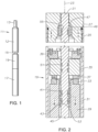
- ESP 11 an electrical well pump assembly (ESP) 11 of a type typically used for oil well pumping operations is illustrated.
- ESP 11 includes a rotary pump 12 that may be a centrifugal pump having a large number of stages, each of the stages having an impeller and a diffuser.
- Pump 12 could also be a progressing cavity pump, which has a helical rotor that rotates within an elastomeric double helical stator. Pump 12 may be suspended in a well on a string of production tubing 13. Pump 12 has an intake 15 and discharges into production tubing 13.
- ESP 11 also includes an electrical motor 17 for driving pump 12.
- Motor 17 connects to pump 12 via a seal section 19, which has means for reducing a pressure differential between lubricant within motor 17 and the hydrostatic pressure of well fluid in the well.
- Intake 15 may be at the lower end of pump 12, in the upper end of seal section 19 or in a separate module.
- ESP 11 may also include a gas separator, and if so intake 15 would be in the gas separator.
- seal section 19 has a shaft 21 extending along a longitudinal axis 23 of a cylindrical housing 25.
- Shaft 21 has a lower splined end (not shown) coupled to a shaft of motor 17 for rotating shaft 21.
- Shaft 21 has an upper splined end (not shown) coupling to a shaft of pump 12 for driving pump 12.
- An upper guide or connector 27 secures by threads to housing 25 and has connecting features on its upper end (not shown) for connecting to pump 12.
- a similar connector or guide is on the lower end of seal section 19 for connecting to motor 17.
- Seal section 19 has a conventional pressure equalizer that is not shown but will normally comprise an elastomeric bag.
- Lubricant from motor 17 communicates through passages in seal section 19 with the interior of the elastomeric bag.
- Well fluid is admitted into the chamber containing the elastomeric bag for imparting hydrostatic well fluid pressure on the elastomeric bag, which in turn applies the hydrostatic pressure to the motor lubricant.
- Seal section 19 also has a primary seal, normally a mechanical face seal, in an upper portion of upper connector 27 for sealing well fluid from contact with the motor lubricant in the interior of seal section 19.
- the seal section 19 has a thrust bearing assembly for transferring down thrust and up thrust imposed on shaft 21 from pump 12 to housing 25. Seal section 19 could include a separate module for the thrust bearing assembly.
- the thrust bearing assembly may have various configurations and in this example has a non-rotating base including a down thrust transfer member 29 secured to housing 25 for non-rotation relative to housing 25. Thrust transfer member 29 may have a helical passage 31 on its exterior to allow the flow of motor lubricant between thrust transfer member 29 and housing 25.
- the base also includes a down thrust bearing 33 mounted on the upper side of thrust transfer member 29 for non- rotation relative to thrust transfer member 29.
- Thrust runner 35 is rigidly secured to shaft 21 above thrust transfer member 29 for rotation in unison with shaft 21.
- Thrust runner 35 is a cylindrical member with bearing pads 37 on its lower side that slidingly engage down thrust bearing 33 to transfer down thrust.
- Thrust runner 35 also transfers any up thrust that may occur on shaft 21 to non-rotating up thrust pads 39.
- Thrust runner 35 has appreciable mass, being much larger in outer diameter than shaft 21. It also has a significant axial dimension from its lower end to its upper end.
- the thrust bearing assembly may also optionally have an inducer or screw pump 41 for circulating motor lubricant.
- screw pump 41 has a helical flight 43 on its exterior that is in close reception with down thrust transfer member bore 45. Screw pump 41 is mounted to shaft 21 for rotation therewith.
- seal section 19 also has radial bearing assemblies at the upper and lower ends of housing 25 for providing radial support to shaft 21.
- Fig. 2 shows only the top bearing assembly, but the bottom bearing assembly will have similar components.
- Those components include a bearing sleeve 47 that rotates with shaft 21.
- Bearing sleeve 47 has an outer diameter in sliding rotational engagement with a non-rotating bushing 49.
- Bushing 49 may be press fit into connector 27.
- Bearing sleeve 47 and bushing 49 may be of carbide material and are immersed in the motor lubricant within seal section 19.
- Seal section 19 has one or more thrust runner tolerance rings or wave springs 51 (two shown) between shaft 21 and thrust runner 35. Seal section 19 may also have one or more screw pump tolerance rings or wave springs 53 (two shown) between shaft 21 and screw pump 41. In addition, seal section 19 may have a radial bearing tolerance ring or wave spring 55 between shaft 21 and bearing sleeve 47. The lower radial bearing (not shown) may also have a tolerance ring or wave spring. The various wave springs 51, 53 and 55 reduce vibration of shaft 21, which might occur particularly at high rotational speeds.
- Wave springs 51, 53 and 55 are located in annular recesses, and in this embodiment, all of the recesses are selectively located on shaft 21.
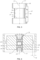
- Fig. 3 shows a portion of shaft 21 that has an annular recess 57 for receiving one of the shaft runner wave springs 51; the other recesses may be identical.
- Upper and lower shoulders 59, 61 define the upper and lower ends of annular recess 57.
- Upper shoulder 59 faces and may be parallel to lower shoulder 61.
- Upper and lower shoulders 59, 61 define a recess cylindrical surface 63 that has a smaller outer diameter than the outer diameter of shaft 21.
- Shaft 21 also has a keyway groove or shaft slot 65 extending most of its length and parallel with axis 23.
- shaft slot 65 has a radial depth no greater than the radial width of shoulders 57, 59, thus it does not extend through recess cylindrical surface 63.
- Shaft slot 65 does extend through upper and lower shoulders 59, 61.
- a portion of a key 67 extends through shaft slot 65 above and below shoulders 59, 61 and alongside recess cylindrical surface 63.
- Key 67 has an inward facing side 66 that is illustrated as being spaced radially outward a slight distance from recess cylindrical surface 63, but it could touch recess cylindrical surface 63.
- the radial distance from axis 23 to key inward facing side 66 is not less than the radial distance from axis 23 to recess cylindrical surface 63 in this example.
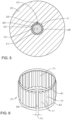
- Fig. 5 which is a transverse sectional view through thrust runner 35, illustrates key 67 installed within keyway slot 65 and fitting within a mating keyway slot in runner bore 68 of thrust runner 35.
- Key 67 imparts rotation of shaft 21 to thrust runner 35.
- the same key 67 may be used to impart rotation to screw pump 41 and bearing sleeve 47 ( Fig. 2 ).
- Runner bore 68 does not have any recesses, rather has the same inner diameter from the upper side of thrust runner 35 to the lower side of thrust runner 35.
- Fig. 5 shows thrust runner wave spring 51 installed in one of the thrust runner recesses 57 surrounded by thrust runner bore 68.
- Thrust runner wave spring 51 is resilient and in frictional engagement with thrust runner bore 68 and with one of the thrust runner recesses 57.
- Thrust runner way spring 51 is split, having two ends 69 that are separated from each other by a gap once installed in recess 57. The gap between ends 69 is large enough for the passage of key 67, which causes thrust runner wave spring 51 to rotate in unison with shaft 21.
- Thrust runner wave spring 51 has outward protruding indentations 71 that exert an outward bias force against thrust runner bore 68.
- Thrust runner wave spring 51 has inward protruding indentations 73 that exert an inward bias force against recess cylindrical surface 63.
- thrust runner wave spring 51 Prior to installation, thrust runner wave spring 51 has a radial or transverse width from its circumscribed outer diameter at outward protruding indentations 71 to its circumscribed inner diameter at inward protruding indentations 73 that is greater than the radial distance from recess cylindrical surface 63 ( Fig. 3 ) to thrust runner bore 68.
- the resiliency of thrust runner wave spring 51 and the split at ends 69 enable it to be resiliently expanded over shaft 21 and snapped into recess 57.
- the resiliency also deflects the radial width of thrust runner wave spring 51, causing it to fit tightly between recess cylindrical surface 63 and thrust runner bore 68.
- the deflection is elastic, less than the yield strength of the material of thrust runner wave spring 51.
- each wave spring 51 has an axial dimension that is only slightly less than the axial distance from upper shoulder 59 to lower shoulder 61 and considerably less than the axial dimension of thrust runner 35 from its lower end to its upper end.
- Fig. 4 also illustrates in exaggerated form an annular clearance that exists between the outer diameter of shaft 21 and the inner diameter of bore 68. A clearance is necessary in order to slide thrust runner 35 over shaft 21 during assembly, but it may be only a few thousandths of an inch.
- Thrust runner 35 is axially secured to shaft 21 so as to prevent any axial movement of thrust runner 35 on shaft 21.
- a multi-piece upper retainer 75 wedges between shaft 21 and thrust runner bore 68.
- a retainer ring 77 which may be a snap ring, secures to shaft 21 at the lower end of thrust runner 35.
- thrust runner wave spring 51 is formed of a metal, such as a spring steel.
- a metal such as a spring steel.
- One example of a suitable metal is Hastelloy.
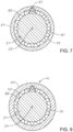
- Wave spring 51 is a curved strip that is formed into a partially cylindrical shape with an end gap 74 between its ends 69. After installation in thrust runner bore 68 ( Fig. 5 ), end gap 74 is slightly greater than the width of key 67 ( Fig. 5 ).
- thrust runner wave spring 51 has a circumferentially extending upper band 81 formed on its upper side and a circumferentially extending lower band 83 formed on its lower side.
- Outward-protruding waves or indentations 71 are permanently formed in thrust runner wave spring 51, creating convex shapes extending around wave spring 51.
- Outward-protruding indentations 71 extend from upper band 81 to lower band 83 and are parallel with axis 23 ( Fig. 4 ).
- Each indentation 71 is elongated, having a length greater than its width.
- Each inward-protruding wave or indentation 73 is located between two of the outward-protruding indentation 71, creating concave shapes on the exterior of thrust runner wave spring 51.
- Inward-protruding indentations 73 are identical to outward-protruding indentations 71 in length and width.
- Each inward-protruding indentation 73 protrudes radially inward from upper and lower bands 81, 83 the same radial distance as each outward-protruding indentation 71.
- outward and inward protruding indentations 71, 73 define a sinusoidal configuration.
- top bearing wave spring 55 and its installation may be identical to thrust runner wave springs 51 and their installations.
- Top bearing wave spring 55 fits tightly between a shaft recess 85 and bearing sleeve bore 87 in the same manner as thrust runner wave springs 51.
- Key 67 engages mating slots in shaft 21 and bearing sleeve bore 87, causing bearing sleeve 47 and bearing sleeve wave spring 55 to rotate with shaft 21.
- the ends of bearing sleeve wave spring 55 are on opposite sides of key 67 in the same manner as described above.
- each screw pump wave spring 53 (two shown in Fig. 2 ) and its installation may be identical to each thrust runner wave spring 51 and its installation. Each fits tightly between a shaft recess 89 and screw pump bore 91 in the same manner as thrust runner wave springs 51. Key 67 engages mating slots in shaft 21 and screw pump bore 91, causing screw pump 41 and screw pump wave spring 53 to rotate with shaft 21. The ends of screw pump wave spring 53 are on opposite sides of key 67 in the same manner as described above.
- motor 17 and portions of seal section 19 are filled with a dielectric lubricant and assembled with pump 12 to form ESP 11.
- An operator runs ESP 11 into a well to pump well fluid.
- Supplying power to the motor 17 rotates shaft 21.
- the various wave springs 51, 53 and 55 tend to reduce vibration of shaft 21, particularly a high speeds.
Landscapes
- Engineering & Computer Science (AREA)
- Mechanical Engineering (AREA)
- General Engineering & Computer Science (AREA)
- Mining & Mineral Resources (AREA)
- Life Sciences & Earth Sciences (AREA)
- Geology (AREA)
- Physics & Mathematics (AREA)
- Fluid Mechanics (AREA)
- Environmental & Geological Engineering (AREA)
- General Life Sciences & Earth Sciences (AREA)
- Geochemistry & Mineralogy (AREA)
- Structures Of Non-Positive Displacement Pumps (AREA)
Claims (7)
- Ensemble pompe submersible (ESP) (11), comprenant :une pompe à fluide de puits (12) ;un moteur (17) ;une section d'étanchéité (19) entre le moteur et la pompe à fluide de puits, la section d'étanchéité comprenant :un logement (25) ayant un axe longitudinal (23) ;un arbre (21) s'étendant à travers le logement sur l'axe, l'arbre étant entraîné par le moteur pour entraîner la pompe à fluide de puits ;une base de palier de butée (33) montée dans le logement pour éviter la rotation par rapport au logement ;un patin de butée (35) ayant un alésage de patin (68) à travers lequel l'arbre s'étend, le patin de butée ayant un diamètre extérieur espacé radialement vers l'intérieur d'une surface intérieure du logement par un jeu annulaire (79), le patin de butée étant fixé à l'arbre pour empêcher le mouvement axial du patin de butée par rapport à l'arbre, le patin de butée étant en engagement rotatif et coulissant avec un côté supérieur de la base du palier de butée ; caractérisé par :un ressort ondulé de patin de butée (51) qui tourne à l'unisson avec l'arbre et le patin de butée, le ressort ondulé du patin de butée étant annulaire, métallique et ayant une surface de diamètre intérieur (73) en contact avec l'arbre et une surface de diamètre extérieur (71) en contact avec l'alésage du patin ;le ressort ondulé de patin de butée ayant une largeur transversale entre la surface du diamètre intérieur et la surface du diamètre extérieur qui est élastiquement déformable, exerçant une force de pression vers l'intérieur contre l'arbre et une force de pression vers l'extérieur contre l'alésage du patin afin de réduire le mouvement de vibration radiale du patin de butée ;une cavité annulaire de patin de butée sur l'arbre, la cavité de patin de butée ayant un épaulement supérieur faisant face à un épaulement inférieur et une surface cylindrique de cavité (63) entre l'épaulement supérieur et l'épaulement inférieur ; et dans lequelle ressort ondulé de patin de butée est situé dans la cavité de patin de butée avec une surface de diamètre intérieur du ressort ondulé du patin de butée en contact avec la surface cylindrique de la cavité ;une fente d'arbre s'étendant axialement, formée sur l'arbre, qui traverse l'épaulement supérieur et l'épaulement inférieur, mais pas la surface cylindrique de la cavité ;une fente d'alésage de patin s'étendant axialement formée dans l'alésage de patin ;une clavette qui s'insère dans les deux fentes pour provoquer la rotation du patin de butée à l'unisson avec l'arbre, la clavette s'étendant à travers les épaulements de la cavité, la clavette ayant une surface tournée vers l'intérieur (66) qui est à une distance radiale de l'axe qui n'est pas inférieure à une distance radiale de l'axe à la surface cylindrique de la cavité ; et dans lequelle ressort ondulé de patin de butée a deux extrémités espacées l'une de l'autre par un espace à travers lequel s'étend la clavette.
- ESP selon la revendication 1, comprenant en outre :la cavité de patin de butée annulaire (57) sur l'arbre et l'épaulement supérieur (59) faisant face à l'épaulement inférieur (61) ; et dans lequelle ressort ondulé de patin de butée est situé dans la cavité de patin de butée et a une dimension axiale inférieure à une distance de l'épaulement inférieur à l'épaulement supérieur.
- ESP selon la revendication 1, dans lequel :
le ressort ondulé de patin de butée comprend deux des ressorts ondulés du patin de butée (51), ayant chacun une surface de diamètre interne en contact avec l'arbre et une surface de diamètre externe en contact avec l'alésage de patin. - ESP selon la revendication 1, comprenant en outre :un connecteur fileté (27) fixé à une extrémité du logement pour raccorder une extrémité de la section d'étanchéité à l'ESP, le connecteur ayant un alésage de connecteur à travers lequel s'étend l'arbre ;une douille de palier (49) montée de manière non rotative et rigide dans l'alésage de connecteur ;un manchon (47) monté sur l'arbre pour tourner avec celui-ci, le manchon ayant un diamètre externe en prise coulissante avec la douille de palier ; etun ressort ondulé de palier annulaire métallique (55) ayant une surface de diamètre interne en contact avec l'arbre et une surface de diamètre externe en contact avec le manchon, le ressort ondulé de palier étant rotatif à l'unisson avec l'arbre et le manchon, le ressort ondulé de palier ayant une largeur radiale entre la surface de diamètre interne et la surface de diamètre externe du ressort ondulé de palier qui est dévié de façon élastique entre l'arbre et le manchon, exerçant une force de sollicitation vers l'intérieur contre l'arbre et une force de sollicitation vers l'extérieur contre le manchon pour réduire le mouvement de vibration radiale de l'arbre.
- ESP selon la revendication 4, comprenant en outre :une cavité de palier annulaire (85) sur l'arbre ; et dans lequelle ressort ondulé de palier est situé dans la cavité de palier.
- ESP selon la revendication 1, comprenant en outre :une pompe à vis (41) ayant un alésage de pompe à vis (91) à travers lequel l'arbre s'étend, la pompe à vis étant montée à l'arbre pour tourner avec celui-ci dans l'alésage de base (45) pour pomper un lubrifiant moteur à travers un anneau d'alésage de base entre l'arbre et l'alésage de base ; etun ressort ondulé de pompe à vis annulaire métallique (53) ayant une surface de diamètre interne en contact avec l'arbre et une surface de diamètre en contact avec l'alésage de la pompe à vis, le ressort ondulé de la pompe à vis étant rotatif à l'unisson avec l'arbre et la pompe à vis, le ressort ondulé de pompe à vis ayant une largeur radiale entre la surface de diamètre interne et la surface de diamètre externe du ressort ondulé de la pompe à vis qui est dévié de façon élastique entre l'arbre et l'alésage de base, exerçant une force de sollicitation vers l'intérieur contre l'arbre et une force de sollicitation vers l'extérieur contre la pompe à vis pour réduire le mouvement de vibration radiale de l'arbre.
- ESP selon la revendication 6, comprenant :une cavité de pompe à vis (89) sur l'arbre ; et dans lequelle ressort ondulé de pompe à vis est situé dans la cavité de pompe à vis.
Applications Claiming Priority (2)
| Application Number | Priority Date | Filing Date | Title |
|---|---|---|---|
| US16/410,080 US11248603B2 (en) | 2019-05-13 | 2019-05-13 | Thrust runner vibration dampening spring in electrical submersible pump |
| PCT/US2020/032573 WO2020232053A1 (fr) | 2019-05-13 | 2020-05-13 | Ressort amortisseur de vibrations de canal de butée dans une pompe submersible électrique |
Publications (3)
| Publication Number | Publication Date |
|---|---|
| EP3969723A1 EP3969723A1 (fr) | 2022-03-23 |
| EP3969723A4 EP3969723A4 (fr) | 2023-02-15 |
| EP3969723B1 true EP3969723B1 (fr) | 2024-03-06 |
Family
ID=73231512
Family Applications (1)
| Application Number | Title | Priority Date | Filing Date |
|---|---|---|---|
| EP20805373.6A Active EP3969723B1 (fr) | 2019-05-13 | 2020-05-13 | Ressort amortisseur de vibrations de canal de butée dans une pompe submersible électrique |
Country Status (4)
| Country | Link |
|---|---|
| US (1) | US11248603B2 (fr) |
| EP (1) | EP3969723B1 (fr) |
| CA (1) | CA3140667C (fr) |
| WO (1) | WO2020232053A1 (fr) |
Families Citing this family (5)
| Publication number | Priority date | Publication date | Assignee | Title |
|---|---|---|---|---|
| JP6783820B2 (ja) * | 2018-05-17 | 2020-11-11 | 本田技研工業株式会社 | 振動体ユニット |
| US11415138B2 (en) * | 2019-08-12 | 2022-08-16 | Baker Hughes Oilfield Operations, Llc | Intermediate bearing in electrical submersible pump |
| US12372102B2 (en) | 2022-04-29 | 2025-07-29 | Schlumberger Technology Corporation | System and method for vibration control |
| US12258950B2 (en) | 2023-01-12 | 2025-03-25 | Gd Energy Products, Llc | Open channel plunger for fracking pumps |
| US20250102040A1 (en) * | 2023-09-27 | 2025-03-27 | Halliburton Energy Services, Inc. | Spring assembly including two separate independent wave springs |
Family Cites Families (12)
| Publication number | Priority date | Publication date | Assignee | Title |
|---|---|---|---|---|
| US3936247A (en) * | 1973-08-15 | 1976-02-03 | Smith International, Inc. | Floating flow restrictors for fluid motors |
| US4222246A (en) * | 1978-12-11 | 1980-09-16 | Roller Bearing Company Of America | Slip clutch |
| DE69730781T2 (de) * | 1996-06-26 | 2005-09-29 | Rolls-Royce Corp., Indianapolis | Lagerkombination für eine Gasturbine |
| US8070426B2 (en) | 2008-05-19 | 2011-12-06 | Baker Hughes Incorporated | System, method and apparatus for open impeller and diffuser assembly for multi-stage submersible pump |
| US10598222B2 (en) * | 2012-01-03 | 2020-03-24 | New Way Machine Components, Inc. | Air bearing for use as seal |
| US9127683B2 (en) | 2012-11-02 | 2015-09-08 | Baker Hughes Incorporated | High temperature radial bearing for electrical submersible pump assembly |
| US10473106B2 (en) * | 2013-05-10 | 2019-11-12 | Halliburton Energy Services, Inc. | Apparatus and system for sealing submersible pump assemblies |
| US9334865B2 (en) | 2013-09-10 | 2016-05-10 | Baker Hughes Incorporated | Self-aligning and vibration damping bearings in a submersible well pump |
| DE102013110849B3 (de) * | 2013-10-01 | 2014-12-11 | Netzsch Pumpen & Systeme Gmbh | Tauchpumpenaggregat zur Verwendung in einem Bohrloch |
| US9765790B2 (en) * | 2014-06-06 | 2017-09-19 | Baker Hughes Incorporated | Tandem thrust bearing with resilient bearing support |
| US9482282B2 (en) * | 2014-08-21 | 2016-11-01 | Zilift Holdings, Ltd. | Bearing for a rotary machine |
| US10371167B2 (en) | 2017-04-27 | 2019-08-06 | Baker Hughes, a GE company. LLC | Thrust bearing base for an electrical submersible well pump having an integrated heat exchanger |
-
2019
- 2019-05-13 US US16/410,080 patent/US11248603B2/en active Active
-
2020
- 2020-05-13 WO PCT/US2020/032573 patent/WO2020232053A1/fr not_active Ceased
- 2020-05-13 CA CA3140667A patent/CA3140667C/fr active Active
- 2020-05-13 EP EP20805373.6A patent/EP3969723B1/fr active Active
Also Published As
| Publication number | Publication date |
|---|---|
| CA3140667C (fr) | 2023-10-10 |
| US11248603B2 (en) | 2022-02-15 |
| US20200362859A1 (en) | 2020-11-19 |
| EP3969723A4 (fr) | 2023-02-15 |
| EP3969723A1 (fr) | 2022-03-23 |
| WO2020232053A1 (fr) | 2020-11-19 |
| CA3140667A1 (fr) | 2020-11-19 |
Similar Documents
| Publication | Publication Date | Title |
|---|---|---|
| EP3969723B1 (fr) | Ressort amortisseur de vibrations de canal de butée dans une pompe submersible électrique | |
| CA3146877C (fr) | Palier intermediaire dans une pompe electrique submersible | |
| US8651836B2 (en) | Torque transmitting rings for sleeves in electrical submersible pumps | |
| EP2914859B1 (fr) | Palier radial à température élevée pour ensemble pompe submersible électrique | |
| US9334865B2 (en) | Self-aligning and vibration damping bearings in a submersible well pump | |
| CA2918462C (fr) | Paliers flexibles resistant a l'abrasion pour pompe de puits subermsible | |
| US10344866B2 (en) | Seal assembly for abrasion resistant bearing of centrifugal pump | |
| EP4055252B1 (fr) | Éléments de centralisation dans une pompe électrique submersible | |
| US9303648B2 (en) | Compliant radial bearing for electrical submersible pump | |
| WO2022204659A1 (fr) | Agencement de diffuseur à interverrouillage dans une pompe électrique submersible | |
| WO2020061227A1 (fr) | Chambre isolée pour fuite de joint mécanique de face dans un ensemble pompe de puits immergée | |
| GB2581447A (en) | Self-aligning and vibration damping bearings in a submersible well pump | |
| GB2438522A (en) | A hydrostatic mechanical seal with local pressurization of seal interface | |
| US12209585B2 (en) | Method and apparatus for an end seal for increasing efficiency of a submersible multistage labyrinth-screw pump | |
| CA3114800A1 (fr) | Empilement d'etages de pompe sollicite par ressort pour ensemble pompe de puits submersible | |
| US20210238969A1 (en) | Motor Bearing With Anti-Rotation Spring For Electrical Submersible Well Pump |
Legal Events
| Date | Code | Title | Description |
|---|---|---|---|
| STAA | Information on the status of an ep patent application or granted ep patent |
Free format text: STATUS: THE INTERNATIONAL PUBLICATION HAS BEEN MADE |
|
| PUAI | Public reference made under article 153(3) epc to a published international application that has entered the european phase |
Free format text: ORIGINAL CODE: 0009012 |
|
| STAA | Information on the status of an ep patent application or granted ep patent |
Free format text: STATUS: REQUEST FOR EXAMINATION WAS MADE |
|
| 17P | Request for examination filed |
Effective date: 20211207 |
|
| AK | Designated contracting states |
Kind code of ref document: A1 Designated state(s): AL AT BE BG CH CY CZ DE DK EE ES FI FR GB GR HR HU IE IS IT LI LT LU LV MC MK MT NL NO PL PT RO RS SE SI SK SM TR |
|
| DAV | Request for validation of the european patent (deleted) | ||
| DAX | Request for extension of the european patent (deleted) | ||
| A4 | Supplementary search report drawn up and despatched |
Effective date: 20230113 |
|
| RIC1 | Information provided on ipc code assigned before grant |
Ipc: F04C 15/00 19680901ALI20230109BHEP Ipc: F04D 29/66 19680901ALI20230109BHEP Ipc: F04D 13/10 19680901ALI20230109BHEP Ipc: F04D 29/041 20060101ALI20230109BHEP Ipc: E21B 43/12 19680901AFI20230109BHEP |
|
| P01 | Opt-out of the competence of the unified patent court (upc) registered |
Effective date: 20230526 |
|
| GRAP | Despatch of communication of intention to grant a patent |
Free format text: ORIGINAL CODE: EPIDOSNIGR1 |
|
| STAA | Information on the status of an ep patent application or granted ep patent |
Free format text: STATUS: GRANT OF PATENT IS INTENDED |
|
| INTG | Intention to grant announced |
Effective date: 20231213 |
|
| RAP3 | Party data changed (applicant data changed or rights of an application transferred) |
Owner name: BAKER HUGHES OILFIELD OPERATIONS, LLC |
|
| GRAS | Grant fee paid |
Free format text: ORIGINAL CODE: EPIDOSNIGR3 |
|
| GRAA | (expected) grant |
Free format text: ORIGINAL CODE: 0009210 |
|
| STAA | Information on the status of an ep patent application or granted ep patent |
Free format text: STATUS: THE PATENT HAS BEEN GRANTED |
|
| AK | Designated contracting states |
Kind code of ref document: B1 Designated state(s): AL AT BE BG CH CY CZ DE DK EE ES FI FR GB GR HR HU IE IS IT LI LT LU LV MC MK MT NL NO PL PT RO RS SE SI SK SM TR |
|
| REG | Reference to a national code |
Ref country code: CH Ref legal event code: EP |
|
| REG | Reference to a national code |
Ref country code: IE Ref legal event code: FG4D |
|
| REG | Reference to a national code |
Ref country code: DE Ref legal event code: R096 Ref document number: 602020026934 Country of ref document: DE |
|
| REG | Reference to a national code |
Ref country code: LT Ref legal event code: MG9D |
|
| PG25 | Lapsed in a contracting state [announced via postgrant information from national office to epo] |
Ref country code: LT Free format text: LAPSE BECAUSE OF FAILURE TO SUBMIT A TRANSLATION OF THE DESCRIPTION OR TO PAY THE FEE WITHIN THE PRESCRIBED TIME-LIMIT Effective date: 20240306 |
|
| REG | Reference to a national code |
Ref country code: NL Ref legal event code: MP Effective date: 20240306 |
|
| PG25 | Lapsed in a contracting state [announced via postgrant information from national office to epo] |
Ref country code: GR Free format text: LAPSE BECAUSE OF FAILURE TO SUBMIT A TRANSLATION OF THE DESCRIPTION OR TO PAY THE FEE WITHIN THE PRESCRIBED TIME-LIMIT Effective date: 20240607 |
|
| PG25 | Lapsed in a contracting state [announced via postgrant information from national office to epo] |
Ref country code: HR Free format text: LAPSE BECAUSE OF FAILURE TO SUBMIT A TRANSLATION OF THE DESCRIPTION OR TO PAY THE FEE WITHIN THE PRESCRIBED TIME-LIMIT Effective date: 20240306 Ref country code: RS Free format text: LAPSE BECAUSE OF FAILURE TO SUBMIT A TRANSLATION OF THE DESCRIPTION OR TO PAY THE FEE WITHIN THE PRESCRIBED TIME-LIMIT Effective date: 20240606 |
|
| PG25 | Lapsed in a contracting state [announced via postgrant information from national office to epo] |
Ref country code: ES Free format text: LAPSE BECAUSE OF FAILURE TO SUBMIT A TRANSLATION OF THE DESCRIPTION OR TO PAY THE FEE WITHIN THE PRESCRIBED TIME-LIMIT Effective date: 20240306 |
|
| PG25 | Lapsed in a contracting state [announced via postgrant information from national office to epo] |
Ref country code: RS Free format text: LAPSE BECAUSE OF FAILURE TO SUBMIT A TRANSLATION OF THE DESCRIPTION OR TO PAY THE FEE WITHIN THE PRESCRIBED TIME-LIMIT Effective date: 20240606 Ref country code: LT Free format text: LAPSE BECAUSE OF FAILURE TO SUBMIT A TRANSLATION OF THE DESCRIPTION OR TO PAY THE FEE WITHIN THE PRESCRIBED TIME-LIMIT Effective date: 20240306 Ref country code: HR Free format text: LAPSE BECAUSE OF FAILURE TO SUBMIT A TRANSLATION OF THE DESCRIPTION OR TO PAY THE FEE WITHIN THE PRESCRIBED TIME-LIMIT Effective date: 20240306 Ref country code: GR Free format text: LAPSE BECAUSE OF FAILURE TO SUBMIT A TRANSLATION OF THE DESCRIPTION OR TO PAY THE FEE WITHIN THE PRESCRIBED TIME-LIMIT Effective date: 20240607 Ref country code: FI Free format text: LAPSE BECAUSE OF FAILURE TO SUBMIT A TRANSLATION OF THE DESCRIPTION OR TO PAY THE FEE WITHIN THE PRESCRIBED TIME-LIMIT Effective date: 20240306 Ref country code: ES Free format text: LAPSE BECAUSE OF FAILURE TO SUBMIT A TRANSLATION OF THE DESCRIPTION OR TO PAY THE FEE WITHIN THE PRESCRIBED TIME-LIMIT Effective date: 20240306 Ref country code: BG Free format text: LAPSE BECAUSE OF FAILURE TO SUBMIT A TRANSLATION OF THE DESCRIPTION OR TO PAY THE FEE WITHIN THE PRESCRIBED TIME-LIMIT Effective date: 20240306 |
|
| REG | Reference to a national code |
Ref country code: AT Ref legal event code: MK05 Ref document number: 1663701 Country of ref document: AT Kind code of ref document: T Effective date: 20240306 |
|
| PG25 | Lapsed in a contracting state [announced via postgrant information from national office to epo] |
Ref country code: SE Free format text: LAPSE BECAUSE OF FAILURE TO SUBMIT A TRANSLATION OF THE DESCRIPTION OR TO PAY THE FEE WITHIN THE PRESCRIBED TIME-LIMIT Effective date: 20240306 Ref country code: LV Free format text: LAPSE BECAUSE OF FAILURE TO SUBMIT A TRANSLATION OF THE DESCRIPTION OR TO PAY THE FEE WITHIN THE PRESCRIBED TIME-LIMIT Effective date: 20240306 |
|
| PG25 | Lapsed in a contracting state [announced via postgrant information from national office to epo] |
Ref country code: NL Free format text: LAPSE BECAUSE OF FAILURE TO SUBMIT A TRANSLATION OF THE DESCRIPTION OR TO PAY THE FEE WITHIN THE PRESCRIBED TIME-LIMIT Effective date: 20240306 |
|
| PG25 | Lapsed in a contracting state [announced via postgrant information from national office to epo] |
Ref country code: NL Free format text: LAPSE BECAUSE OF FAILURE TO SUBMIT A TRANSLATION OF THE DESCRIPTION OR TO PAY THE FEE WITHIN THE PRESCRIBED TIME-LIMIT Effective date: 20240306 |
|
| PG25 | Lapsed in a contracting state [announced via postgrant information from national office to epo] |
Ref country code: IS Free format text: LAPSE BECAUSE OF FAILURE TO SUBMIT A TRANSLATION OF THE DESCRIPTION OR TO PAY THE FEE WITHIN THE PRESCRIBED TIME-LIMIT Effective date: 20240706 |
|
| PG25 | Lapsed in a contracting state [announced via postgrant information from national office to epo] |
Ref country code: SM Free format text: LAPSE BECAUSE OF FAILURE TO SUBMIT A TRANSLATION OF THE DESCRIPTION OR TO PAY THE FEE WITHIN THE PRESCRIBED TIME-LIMIT Effective date: 20240306 Ref country code: PT Free format text: LAPSE BECAUSE OF FAILURE TO SUBMIT A TRANSLATION OF THE DESCRIPTION OR TO PAY THE FEE WITHIN THE PRESCRIBED TIME-LIMIT Effective date: 20240708 |
|
| PG25 | Lapsed in a contracting state [announced via postgrant information from national office to epo] |
Ref country code: CZ Free format text: LAPSE BECAUSE OF FAILURE TO SUBMIT A TRANSLATION OF THE DESCRIPTION OR TO PAY THE FEE WITHIN THE PRESCRIBED TIME-LIMIT Effective date: 20240306 Ref country code: EE Free format text: LAPSE BECAUSE OF FAILURE TO SUBMIT A TRANSLATION OF THE DESCRIPTION OR TO PAY THE FEE WITHIN THE PRESCRIBED TIME-LIMIT Effective date: 20240306 |
|
| PG25 | Lapsed in a contracting state [announced via postgrant information from national office to epo] |
Ref country code: AT Free format text: LAPSE BECAUSE OF FAILURE TO SUBMIT A TRANSLATION OF THE DESCRIPTION OR TO PAY THE FEE WITHIN THE PRESCRIBED TIME-LIMIT Effective date: 20240306 |
|
| PG25 | Lapsed in a contracting state [announced via postgrant information from national office to epo] |
Ref country code: PL Free format text: LAPSE BECAUSE OF FAILURE TO SUBMIT A TRANSLATION OF THE DESCRIPTION OR TO PAY THE FEE WITHIN THE PRESCRIBED TIME-LIMIT Effective date: 20240306 |
|
| PG25 | Lapsed in a contracting state [announced via postgrant information from national office to epo] |
Ref country code: SK Free format text: LAPSE BECAUSE OF FAILURE TO SUBMIT A TRANSLATION OF THE DESCRIPTION OR TO PAY THE FEE WITHIN THE PRESCRIBED TIME-LIMIT Effective date: 20240306 |
|
| PG25 | Lapsed in a contracting state [announced via postgrant information from national office to epo] |
Ref country code: SM Free format text: LAPSE BECAUSE OF FAILURE TO SUBMIT A TRANSLATION OF THE DESCRIPTION OR TO PAY THE FEE WITHIN THE PRESCRIBED TIME-LIMIT Effective date: 20240306 Ref country code: SK Free format text: LAPSE BECAUSE OF FAILURE TO SUBMIT A TRANSLATION OF THE DESCRIPTION OR TO PAY THE FEE WITHIN THE PRESCRIBED TIME-LIMIT Effective date: 20240306 Ref country code: RO Free format text: LAPSE BECAUSE OF FAILURE TO SUBMIT A TRANSLATION OF THE DESCRIPTION OR TO PAY THE FEE WITHIN THE PRESCRIBED TIME-LIMIT Effective date: 20240306 Ref country code: PT Free format text: LAPSE BECAUSE OF FAILURE TO SUBMIT A TRANSLATION OF THE DESCRIPTION OR TO PAY THE FEE WITHIN THE PRESCRIBED TIME-LIMIT Effective date: 20240708 Ref country code: PL Free format text: LAPSE BECAUSE OF FAILURE TO SUBMIT A TRANSLATION OF THE DESCRIPTION OR TO PAY THE FEE WITHIN THE PRESCRIBED TIME-LIMIT Effective date: 20240306 Ref country code: IS Free format text: LAPSE BECAUSE OF FAILURE TO SUBMIT A TRANSLATION OF THE DESCRIPTION OR TO PAY THE FEE WITHIN THE PRESCRIBED TIME-LIMIT Effective date: 20240706 Ref country code: EE Free format text: LAPSE BECAUSE OF FAILURE TO SUBMIT A TRANSLATION OF THE DESCRIPTION OR TO PAY THE FEE WITHIN THE PRESCRIBED TIME-LIMIT Effective date: 20240306 Ref country code: CZ Free format text: LAPSE BECAUSE OF FAILURE TO SUBMIT A TRANSLATION OF THE DESCRIPTION OR TO PAY THE FEE WITHIN THE PRESCRIBED TIME-LIMIT Effective date: 20240306 Ref country code: AT Free format text: LAPSE BECAUSE OF FAILURE TO SUBMIT A TRANSLATION OF THE DESCRIPTION OR TO PAY THE FEE WITHIN THE PRESCRIBED TIME-LIMIT Effective date: 20240306 |
|
| REG | Reference to a national code |
Ref country code: DE Ref legal event code: R119 Ref document number: 602020026934 Country of ref document: DE |
|
| PG25 | Lapsed in a contracting state [announced via postgrant information from national office to epo] |
Ref country code: IT Free format text: LAPSE BECAUSE OF FAILURE TO SUBMIT A TRANSLATION OF THE DESCRIPTION OR TO PAY THE FEE WITHIN THE PRESCRIBED TIME-LIMIT Effective date: 20240306 |
|
| REG | Reference to a national code |
Ref country code: CH Ref legal event code: PL |
|
| PG25 | Lapsed in a contracting state [announced via postgrant information from national office to epo] |
Ref country code: IT Free format text: LAPSE BECAUSE OF FAILURE TO SUBMIT A TRANSLATION OF THE DESCRIPTION OR TO PAY THE FEE WITHIN THE PRESCRIBED TIME-LIMIT Effective date: 20240306 |
|
| PG25 | Lapsed in a contracting state [announced via postgrant information from national office to epo] |
Ref country code: MC Free format text: LAPSE BECAUSE OF FAILURE TO SUBMIT A TRANSLATION OF THE DESCRIPTION OR TO PAY THE FEE WITHIN THE PRESCRIBED TIME-LIMIT Effective date: 20240306 |
|
| PLBE | No opposition filed within time limit |
Free format text: ORIGINAL CODE: 0009261 |
|
| STAA | Information on the status of an ep patent application or granted ep patent |
Free format text: STATUS: NO OPPOSITION FILED WITHIN TIME LIMIT |
|
| PG25 | Lapsed in a contracting state [announced via postgrant information from national office to epo] |
Ref country code: DK Free format text: LAPSE BECAUSE OF FAILURE TO SUBMIT A TRANSLATION OF THE DESCRIPTION OR TO PAY THE FEE WITHIN THE PRESCRIBED TIME-LIMIT Effective date: 20240306 |
|
| PG25 | Lapsed in a contracting state [announced via postgrant information from national office to epo] |
Ref country code: LU Free format text: LAPSE BECAUSE OF NON-PAYMENT OF DUE FEES Effective date: 20240513 |
|
| PG25 | Lapsed in a contracting state [announced via postgrant information from national office to epo] |
Ref country code: MC Free format text: LAPSE BECAUSE OF FAILURE TO SUBMIT A TRANSLATION OF THE DESCRIPTION OR TO PAY THE FEE WITHIN THE PRESCRIBED TIME-LIMIT Effective date: 20240306 Ref country code: LU Free format text: LAPSE BECAUSE OF NON-PAYMENT OF DUE FEES Effective date: 20240513 Ref country code: DK Free format text: LAPSE BECAUSE OF FAILURE TO SUBMIT A TRANSLATION OF THE DESCRIPTION OR TO PAY THE FEE WITHIN THE PRESCRIBED TIME-LIMIT Effective date: 20240306 Ref country code: CH Free format text: LAPSE BECAUSE OF NON-PAYMENT OF DUE FEES Effective date: 20240531 |
|
| 26N | No opposition filed |
Effective date: 20241209 |
|
| REG | Reference to a national code |
Ref country code: BE Ref legal event code: MM Effective date: 20240531 |
|
| PG25 | Lapsed in a contracting state [announced via postgrant information from national office to epo] |
Ref country code: DE Free format text: LAPSE BECAUSE OF NON-PAYMENT OF DUE FEES Effective date: 20241203 |
|
| PG25 | Lapsed in a contracting state [announced via postgrant information from national office to epo] |
Ref country code: IE Free format text: LAPSE BECAUSE OF NON-PAYMENT OF DUE FEES Effective date: 20240513 |
|
| PG25 | Lapsed in a contracting state [announced via postgrant information from national office to epo] |
Ref country code: SI Free format text: LAPSE BECAUSE OF FAILURE TO SUBMIT A TRANSLATION OF THE DESCRIPTION OR TO PAY THE FEE WITHIN THE PRESCRIBED TIME-LIMIT Effective date: 20240306 Ref country code: BE Free format text: LAPSE BECAUSE OF NON-PAYMENT OF DUE FEES Effective date: 20240531 |
|
| PG25 | Lapsed in a contracting state [announced via postgrant information from national office to epo] |
Ref country code: FR Free format text: LAPSE BECAUSE OF NON-PAYMENT OF DUE FEES Effective date: 20240531 |
|
| PGFP | Annual fee paid to national office [announced via postgrant information from national office to epo] |
Ref country code: GB Payment date: 20250423 Year of fee payment: 6 |
|
| PGFP | Annual fee paid to national office [announced via postgrant information from national office to epo] |
Ref country code: NO Payment date: 20250424 Year of fee payment: 6 |
|
| PG25 | Lapsed in a contracting state [announced via postgrant information from national office to epo] |
Ref country code: CY Free format text: LAPSE BECAUSE OF FAILURE TO SUBMIT A TRANSLATION OF THE DESCRIPTION OR TO PAY THE FEE WITHIN THE PRESCRIBED TIME-LIMIT; INVALID AB INITIO Effective date: 20200513 |
|
| PG25 | Lapsed in a contracting state [announced via postgrant information from national office to epo] |
Ref country code: HU Free format text: LAPSE BECAUSE OF FAILURE TO SUBMIT A TRANSLATION OF THE DESCRIPTION OR TO PAY THE FEE WITHIN THE PRESCRIBED TIME-LIMIT; INVALID AB INITIO Effective date: 20200513 |