EP3970099B1 - Dispositif permettant d'indiquer l'état d'un récipient et procédés associés - Google Patents
Dispositif permettant d'indiquer l'état d'un récipient et procédés associés Download PDFInfo
- Publication number
- EP3970099B1 EP3970099B1 EP20728683.2A EP20728683A EP3970099B1 EP 3970099 B1 EP3970099 B1 EP 3970099B1 EP 20728683 A EP20728683 A EP 20728683A EP 3970099 B1 EP3970099 B1 EP 3970099B1
- Authority
- EP
- European Patent Office
- Prior art keywords
- flap
- container
- items
- containers
- slidable member
- Prior art date
- Legal status (The legal status is an assumption and is not a legal conclusion. Google has not performed a legal analysis and makes no representation as to the accuracy of the status listed.)
- Active
Links
Images


Classifications
-
- G—PHYSICS
- G06—COMPUTING OR CALCULATING; COUNTING
- G06Q—INFORMATION AND COMMUNICATION TECHNOLOGY [ICT] SPECIALLY ADAPTED FOR ADMINISTRATIVE, COMMERCIAL, FINANCIAL, MANAGERIAL OR SUPERVISORY PURPOSES; SYSTEMS OR METHODS SPECIALLY ADAPTED FOR ADMINISTRATIVE, COMMERCIAL, FINANCIAL, MANAGERIAL OR SUPERVISORY PURPOSES, NOT OTHERWISE PROVIDED FOR
- G06Q10/00—Administration; Management
- G06Q10/08—Logistics, e.g. warehousing, loading or distribution; Inventory or stock management
- G06Q10/087—Inventory or stock management, e.g. order filling, procurement or balancing against orders
-
- G—PHYSICS
- G06—COMPUTING OR CALCULATING; COUNTING
- G06K—GRAPHICAL DATA READING; PRESENTATION OF DATA; RECORD CARRIERS; HANDLING RECORD CARRIERS
- G06K19/00—Record carriers for use with machines and with at least a part designed to carry digital markings
- G06K19/06—Record carriers for use with machines and with at least a part designed to carry digital markings characterised by the kind of the digital marking, e.g. shape, nature, code
- G06K19/06009—Record carriers for use with machines and with at least a part designed to carry digital markings characterised by the kind of the digital marking, e.g. shape, nature, code with optically detectable marking
- G06K19/06018—Record carriers for use with machines and with at least a part designed to carry digital markings characterised by the kind of the digital marking, e.g. shape, nature, code with optically detectable marking one-dimensional coding
- G06K19/06028—Record carriers for use with machines and with at least a part designed to carry digital markings characterised by the kind of the digital marking, e.g. shape, nature, code with optically detectable marking one-dimensional coding using bar codes
-
- G—PHYSICS
- G06—COMPUTING OR CALCULATING; COUNTING
- G06Q—INFORMATION AND COMMUNICATION TECHNOLOGY [ICT] SPECIALLY ADAPTED FOR ADMINISTRATIVE, COMMERCIAL, FINANCIAL, MANAGERIAL OR SUPERVISORY PURPOSES; SYSTEMS OR METHODS SPECIALLY ADAPTED FOR ADMINISTRATIVE, COMMERCIAL, FINANCIAL, MANAGERIAL OR SUPERVISORY PURPOSES, NOT OTHERWISE PROVIDED FOR
- G06Q10/00—Administration; Management
- G06Q10/08—Logistics, e.g. warehousing, loading or distribution; Inventory or stock management
-
- G—PHYSICS
- G09—EDUCATION; CRYPTOGRAPHY; DISPLAY; ADVERTISING; SEALS
- G09F—DISPLAYING; ADVERTISING; SIGNS; LABELS OR NAME-PLATES; SEALS
- G09F3/00—Labels, tag tickets, or similar identification or indication means; Seals; Postage or like stamps
- G09F3/02—Forms or constructions
- G09F3/0297—Forms or constructions including a machine-readable marking, e.g. a bar code
-
- G—PHYSICS
- G09—EDUCATION; CRYPTOGRAPHY; DISPLAY; ADVERTISING; SEALS
- G09F—DISPLAYING; ADVERTISING; SIGNS; LABELS OR NAME-PLATES; SEALS
- G09F7/00—Signs, name or number plates, letters, numerals, or symbols; Panels or boards
- G09F7/02—Signs, plates, panels or boards using readily-detachable elements bearing or forming symbols
- G09F7/04—Signs, plates, panels or boards using readily-detachable elements bearing or forming symbols the elements being secured or adapted to be secured by magnetic means
-
- G—PHYSICS
- G09—EDUCATION; CRYPTOGRAPHY; DISPLAY; ADVERTISING; SEALS
- G09F—DISPLAYING; ADVERTISING; SIGNS; LABELS OR NAME-PLATES; SEALS
- G09F7/00—Signs, name or number plates, letters, numerals, or symbols; Panels or boards
- G09F7/02—Signs, plates, panels or boards using readily-detachable elements bearing or forming symbols
- G09F7/08—Signs, plates, panels or boards using readily-detachable elements bearing or forming symbols the elements being secured or adapted to be secured by means of grooves, rails, or slits
- G09F7/10—Signs, plates, panels or boards using readily-detachable elements bearing or forming symbols the elements being secured or adapted to be secured by means of grooves, rails, or slits and slideably mounted
-
- G—PHYSICS
- G09—EDUCATION; CRYPTOGRAPHY; DISPLAY; ADVERTISING; SEALS
- G09F—DISPLAYING; ADVERTISING; SIGNS; LABELS OR NAME-PLATES; SEALS
- G09F3/00—Labels, tag tickets, or similar identification or indication means; Seals; Postage or like stamps
- G09F3/02—Forms or constructions
- G09F2003/0214—Stock management
- G09F2003/0219—Stock management to keep record of the use of a product
Definitions
- a manually actuateable device having first, second and third indicating state, wherein the third indicating state is activateable in one of the first and second states.
- the device is useful in signalling a status of a container.
- the Kanban card system signals a need to replenish a container.
- a physical card containing information about the item is placed within the container; when the container is depleted or near-depleted the card becomes accessible or visible.
- a "Kanban trigger" is created which may be manual or automatic, a purchase order is released, sometimes with a quantity for the supplier defined on the card, and the supplier is instructed to dispatch the items.
- Kanban card system There are numerous problem of the Kanban card system. Cards may be mis-assigned; a card that has been placed in the wrong container will trigger re-ordering of the wrong item which can have severe implications in a care environment. There is a lack of knowledge of an order status of an item; where a container is empty, a consumer can expend valuable time resource enquiring on status with order management. In an environment such as an industrial warehouse supply or hospital, hundreds of container may be present, and re-ordering may automated, ( e.g . by barcodes). In such environment it is not apparent to the consumer whether the empty container has been notified, and it is burdensome and time-consuming to follow up.
- medical consumable items e.g . needles, syringes, gauze, pharmaceuticals
- a status-indicating device (10) for indicating a status of a container comprising:
- the permanent magnet (130) may be configured to de-activate the linear ratchet mechanism (250) when the flap (200) is in the second (220) position.
- the flap (200) may comprise:
- the positions of the flap (200) and slidable member (300) may be machine-readable; and/or first visual indicating surface (214) and second visual indicating surface (224) may be machine-readable.
- the second visual indicating surface (224) comprises a machine-readable barcode.
- the device (10) may be further provided with a bracket (400) configured for dismountable attachment of the device (10) to a container, and configured to place the device (10) in an upright orientation wherein the second (220) position is above the first (210) position.
- a bracket (400) configured for dismountable attachment of the device (10) to a container, and configured to place the device (10) in an upright orientation wherein the second (220) position is above the first (210) position.
- the magnetically-regulated linear ratchet mechanism (250) may comprise a ratchet and pawl, wherein:
- a method for determining individual statuses of containers in a set of containers, each container holding a stock of items comprising:
- the devices (10) may be attached to the containers in the set of containers are read by a camera having a steerable field of view, FOV, direction wherein the camera is positioned and the containers are arranged such that the camera in a single FOV direction captures an image of some of the devices (10) of the set of containers, and the camera in multiple FOV directions captures multiple images covering all of the devices (10) of the set of containers, and the status of each and every container in the set of containers is determined from the multiple images.
- FOV steerable field of view
- the second visual indicating surface (224) and optionally first visual indicating surface (214) of the devices (10) may be read by the camera.
- a change in state of a device (10) from 1 st state to 2 nd state may release a purchase order of items associated with the device (10) and container.
- the terms "one or more” or “at least one”, such as one or more or at least one member(s) of a group of members, is clear per se , by means of further exemplification, the term encompasses inter alia a reference to any one of said members, or to any two or more of said members, such as, e.g. , any ⁇ 3, ⁇ 4, ⁇ 5, ⁇ 6 or ⁇ 7 etc. of said members, and up to all said members.
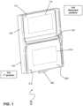
- a status-indicating device 10 for indicating a status of a container.
- the device has three stable states each of which is visually- and optionally machine-readable, indicating different statuses of the container. Exemplary devices are shown in FIGs. 1 , 2 and 3 .
- the status of the container may be indicative of a need or not to replenish items held within the container.
- the device (10) is manually actuatable, meaning the consumer can manually adjust the status responsive to the perceived quantity of items in the container.
- Visually-readable means that the status can be perceived by the human eye ( e.g. of the consumer).
- Machine-readable means that the status can be read by a machine comprising a sensor such as an optical sensor (e.g. CCD) and/or radiofrequency sensor (e.g. RFID).
- a 1 st state (e.g. FIG. 1 ) of the device (10) indicates that the quantity of items in the container is sufficient, or above a threshold level, or that the container does not need to be replenished.
- a 2 nd state (e.g. FIG. 2 ) of the device (10) indicates that the quantity of items in the container is not sufficient, or below a threshold level, or that the container needs to be replenished.
- a 2 nd state e.g. FIG. 2 ) indicates items need to be re-ordered.
- a 3 rd state (e.g. FIG. 3 ) of the device (10) indicates that the quantity of items in the container is not sufficient, or below a threshold level, or that the container needs to be replenished, and that the items have been re-ordered.
- Each state is stable, and the 3 rd state can only be activated after the 2 nd state has been selected to avoid misinforming the consumer.
- the 2 nd state may be manually set by the consumer when it is visually evident that the quantity of items in the container is not sufficient, or is below a threshold level, or that the container needs to be replenished. Different items may have different consumption rates, and the consumer will know the optimum time to activate the 2 nd state, for example, when there is 0, 1, or 3 items remaining.
- the device (10) comprises a support panel (100) having a forward-facing side (110) (e.g. FIGs. 1-3 ) and an opposing back-facing side (120) as shown, for instance, in FIG. 4A .
- a flap (200) is attached by a hinge (102) in relation the forward-facing side (110) of the support panel (100).
- the hinge may be disposed such that an axis of rotation of the hinge is horizontal.
- the flap (200) is manually actuateable between a first (210) and second (220) position.
- the first position (210) may correspond to a downward orientated flap (200) ( e.g. FIG. 1 ).
- the second position (220) may correspond to an upward orientated flap (200) ( e.g. FIG. 2 ).
- the device (10) may have an upright orientation wherein the second (220) position is above the first (210) position.
- the flap (200) in the first position (210) corresponds to the 1 st state ( e.g. FIG. 1 ).
- the flap (200) has a first side (212) optionally disposed with a first visual indicating surface (214).
- the first side (212) and hence first visual indicating surface (214) are visible when the flap is in the first position (210).
- Position of the flap in first position (210) can be read by the consumer and/or machine.
- the first visual indicating surface (214) in first position (210) can be read by the consumer and/or machine.
- the first side (212) and hence first visual indicating surface (214) are concealed when the flap is in the second position (220), and cannot be read by the consumer or machine.
- the flap (200) in the second position (220) corresponds to the 2 nd state ( e.g. FIG. 2 ).
- the flap (200) has a second side (222) opposing the first side (212), optionally disposed with a second visual indicating surface (224).
- the second side (222) and hence second visual indicating surface (224) are visible when the flap is in the second position (220).
- Position of the flap in second position (220) can be read by the consumer or machine.
- the second visual indicating surface (224) in second position (220) can be read by the consumer and/or machine.
- the second side (222) and hence first visual indicating surface (224) are concealed when the flap is in the first position (210), and cannot be read by the consumer or machine.
- a permanent magnet (130) disposed in relation to the support panel (100) configured to retain/engage the flap (200) in the second position (220) or 2 nd state ( e.g. FIG. 4A to 4F , FIG. 5 ).
- the permanent magnet (130) may be provided attached to the support panel (100) by a bracket (400).
- a slidable member (300) is slidably attached to the flap (200) ( e.g. FIG. 3 , 4A to 4F , FIG. 5 ).
- the slidable member (300) is manually actuateable between a retracted (316) ( e.g. FIGs. 1 and 2 ) and deployed (318) position ( e.g. FIG. 3 ).
- a retracted (316) e.g. FIGs. 1 and 2
- deployed (318) position e.g. FIG. 3
- an exposed portion (312) of the slidable member (300) is unmasked.
- the slidable member (300) in the deployed position (318) protrudes from behind the flap (200) second side (222) thereby unmasking the exposed portion (312).
- the exposed portion (312) may optionally be disposed with a third visual indicating surface (314).
- the slidable member (300) in the retracted position (316) may be positioned at least partially behind the flap (200) second side (222) thereby masking the exposed portion (312).
- the exposed portion (312) is disposed with a third visual indicating surface (314)
- the third visual indicating surface (310) is masked in the retracted position (316).
- Position of the slidable member (300) in the retracted (316) or deployed (318) position may be readable by the consumer and/or machine.
- the third visual indicating surface (314) in the deployed (318) position may be readable by the consumer and/or machine.
- the third visual indicating surface (314) in the retracted (316) position is concealed and may not be readable by the consumer or machine.
- the device (100) can hence be set to one of the three states which may be detectable by the position of the flap (200) and slidable member (300). Further, one of the three states may be detectable by reading of the visual indicating surfaces (214, 224, 314).
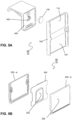
- the flap (200) may be formed from 2 parts (200,-a; 200, -b) and the slidable member (300) may be disposed or sandwiched between both parts ( e.g. FIG. 4A to 4F , FIG. 5 ).
- Movement of the slidable member (300) from the retracted position (316) to the deployed (318) position when the flap (200) is in the first position (210) may be prevented. This circumvents accidental movement of the slidable member (300) to the deployed (318) position when the flap (200) is pointing downwards, which could lead to false information.
- the flap (200) and slidable member (300) may be provided with a magnetically-regulated linear ratchet mechanism (250) ( e.g. FIG. 4A to 4F , FIG. 5 ).
- the magnetically-regulated linear ratchet mechanism (250) has an activated state in which ratchet functionality is enabled to restrict movement of the slidable member (300) to one direction (deployed to retracted only), and a de-activated state in which the ratchet is disabled and the slidable member (300) is able to move in both directions (deployed to and from retracted).
- the ratchet In the presence of a magnetic field, the ratchet is disabled allowing movement of the slidable member (300) back and forth between the retracted (316) and deployed (318) positions. In the absence of a magnetic field, the ratchet may be enabled allowing a return of the slidable member (300) from the deployed position (318) to the retracted (316) position, but preventing deployment of the slidable member (300) from the retracted (316) position to the deployed position (318).
- the permanent magnet (130) disposed in relation to the support panel (100) configured to retain/engage the flap (200) in the second position (220) or 2 nd state may also be configured to deactivate the ratchet mechanism (disable the ratchet), allowing deployment and return of the slidable member (300) from the retracted (316) position to the deployed (318) position to the while the flap (200) is in the second position (220) or 2 nd state.
- the linear ratchet mechanism (250) may comprise a leaf spring (252) biased in an open position disposed in fixed relation to the slidable member (300).
- the leaf spring (252) in the open position provides a ratchet (gear or teeth) part of the mechanism.
- the ratchet mechanism may further comprise a pawl (256) disposed in fixed relation to the flap (200). Sliding movement of the ratchet (gear or teeth) in relation to the pawl (256) is restricted to one direction when the linear ratchet mechanism (250) is activated.
- the linear ratchet mechanism (250) is configured such that the sliding movement of the open leaf spring (252) in the retracted direction over the pawl (256) compresses the leaf spring (252). Further retraction of the leaf spring (252) causes an end edge (254) of the leaf spring (252) to pass past the pawl (256) and open again. Sliding movement of the leaf spring (252) in the opposite direction is prevented by the end edge (254) of the open leaf spring (252) contacting the pawl (256) that acts as a stop member.
- the ratchet functionality is disabled by lowering the gear tooth, and the slidable member (300) can move in both directions.
- the application of the magnetic field moves the leaf spring (252) from an open (ratchet-enabled) position, to a closed (ratchet disabled) position.
- the activation of the linear ratchet mechanism (250) is synchronised with the flap in the 1 st position (210), and deactivation of the linear ratchet mechanism (250) is synchronised with the flap (200) in the 2 nd position (220).
- the magnetically-regulated ratchet mechanism allows a sequential signalling of status of a container that can be read by human eye and machine that reduces ambiguity.
- FIG. 4A to 4F show an exemplary sequence of steps for setting the device (10) in the 1 st , 2 nd , and 3 rd states, and activation/deactivation of the linear ratchet mechanism (250).
- the flap (200) is mounted by a hinge on the forward-facing side (110) of support panel (100) and is disposed in the first position corresponding to the 1 st state.
- Sandwiched between both parts of the flap (200, -a, -b) is the slidable member (300).
- the linear ratchet mechanism (250) is activated; movement of the slidable member (300) is restricted to retraction only, and deployment is prevented.
- the ratchet mechanism comprises a leaf spring (252) in fixed relation to the slidable member (300) and biased in an open configuration.
- the leaf spring (252) in an open configuration is a ratchet and a pawl (256) is disposed on the flap (200, -a, -b). Sliding movement of the open leaf spring (252) in the deployed direction is prevented by the end edge (254) of the leaf spring (252) contacting the pawl (256) that act as a stop member.
- the flap (200) is disposed in the second position corresponding to the 2 nd state.
- the linear ratchet mechanism (250) is deactivated.
- the leaf spring (252) is brought in proximity to the magnet (130), causing the leaf spring (252) to close and sequestering its ratchet functionality.
- the closed leaf spring (252) can move without hindrance from the pawl (256) between the deployed (318) ( FIG. 4B ) and retracted positions (316) ( FIG. 4C ) positions.
- the flap (200) is disposed in the first position corresponding to the 1 st state.
- the linear ratchet mechanism (250) is activated again at it is removed from the magnet (130). Movement of the slidable member (300) in the retracted direction advances the open leaf spring (252) over the pawl (256) that compresses the leaf spring (252) ( FIG . 4E ). When end edge (254) of the leaf spring (252) has moved past the pawl (256), the leaf spring (252) opens again. Sliding movement of the open leaf spring (252) in the deployed direction is prevented by the end edge (254) of the leaf spring (252) contacting the pawl (256) that acts as a stop member ( FIG. 4F ).
- the support panel, flap, slidable member made at least partially from polymeric material, optionally mouldable.
- the leaf spring made from magnetically-attractive material, preferably, spring steel.
- the magnetic is made at least partially from neodymium or an alternative magnetic material.
- the first visual indicating surface (214) exposed in the flap (200) first position (210) may be read by human eye, and optionally by a machine.
- First visual indicating surface (214) may comprise a colour coding (e.g. green marking).
- First visual indicating surface (214) may comprise a machine-readable marking (e.g. 1D, 2D, holographic bar code).
- the second visual indicating surface (224) exposed in the flap (200) second position (220) may be read by human eye, and optionally by a machine.
- Second visual indicating surface (224) may comprise a colour coding (e.g. red marking).
- Second visual indicating surface (224) may comprise a machine-readable marking (e.g. 1D, 2D, holographic bar code).
- the third visual indicating surface (314) exposed in the slidable member (300) deployed position (318) may be read by human eye, and optionally by a machine.
- Third visual indicating surface (314) may comprise a colour coding ( e.g. orange marking).
- Third visual indicating surface (314) may comprise a machine-readable marking ( e.g. 1D, 2D, holographic bar code).
- the support panel (100) may be disposed with a first maskable region (114) on the forward-facing side (110).
- the first maskable region (114) may be unmasked in the flap (200) first position (210).
- the first maskable region (114) may be masked in the flap (200) second position (210).
- the first maskable region (114) may be disposed with a machine-readable element such as an optical marking, 1D, 2D or holographic barcode, RFID tag, that is unreadable when masked and readable when unmasked.
- the support panel (100) is disposed with a second maskable region (124) on forward-facing side (110).
- the second maskable region (124) may be unmasked in the flap (200) second position (220).
- the second maskable region (124) may be masked in the flap (200) first position (210).
- the second maskable surface (124) may be disposed with a machine-readable element such as a 1D, 2D, or holographic barcode, RFID tag that is unreadable when masked and readable when unmasked.
- the second maskable surface (124) may be provided with an RFID tag and the flap (200) is configured to inhibit reading of the RFID tag in the second (220) position.
- the flap (200) may comprise comprises an RF shield, such as a metallic sheet.
- the metal sheer may be continuous or formed as a mesh or grill.
- the device (10) may be provided with a bracket (400) configured for dismountable attachment of the device (10) to a container.
- the bracket (400) may be dismountably attached to the support panel (100) back-facing side (120).
- the bracket (400) may comprise a clamp or clip for dismountable attachment of the device (10) to the container.
- the bracket (400) may be configured to place the device (10) in an upright orientation wherein the second (220) position is above the first (210) position.
- the bracket (400) may contain a holder (402) for the permanent magnet.
- the bracket (400) attached to the container reduces the possibility for mis-assignment of the device (10) to a wrong container as the bracket prevents that the device (10) is freely moveable.
- the container may be a medical basket.
- the medical basket may be provided with a rim to which the bracket (400) attaches.
- FIGs. 5A and 5B show exploded view of an exemplary device (10).
- the bracket (400) contains a holder (402) for the permanent magnet (130).
- the bracket (400) attached to the support panel (100) aligns the permanent magnet (130) with the first maskable region (114).
- the second maskable region (124) is indicated.
- the flap (200) comprises two panels (200, -a, -b) that flank the slidable member (300). Integrated into the slidable member is the leaf spring (252).
- a method for determining individual statuses of containers in a set of containers, each container holding a stock of items comprising:
- the step of setting the flap (200) to the first position (210) and the slidable member (300) to the retracted position (316) may expose the first visual indicating surface (214), that may be readable by eye and optionally by machine.
- the step of setting the flap (200) to the first position (210) may also activate the ratchet, thereby preventing setting of slidable member (300) to the deployed position (318), but allowing setting of slidable member (300) to the retracted position (316).
- the step of setting the flap (200) to the second position (220) may expose the second visual indicating surface (224), that may be readable by eye and optionally by machine.
- the step of setting the flap (200) to the second position (220) may also deactivate the ratchet, thereby allowing the slidable member (300) to be set repeatably between the deployed position (318) and the retracted position (316).
- the method further comprises a step of reading, by the machine, machine-readable parts of first visual indicating surface (214) or second visual indicating surface (224), and logging the status of the container (500).
- the one or more devices (10) may be attached to the container in an upright orientation wherein the second (220) position is above the first (210) position.
- a container provided with one or more devices (10) as described herein.
- the method comprises providing each container with a manually-settable camera-readable status indicator, CRSI.
- CRSI include the device (10) of F IGs. 1-5B ,and the CRSls of FIGs. 6A-C (12) and 7A-C (14). Examples of a CRSI (20, 14a-b, 14a-p) attached to a container (46a-b, 46a-p) is shown in FIGs. 8-9 .
- the CRSI (20) in one settable position may display a barcode (1D, 2D, holographic) (22) that is not displayed in the other settable position.
- a camera (40) having a steerable field of view (42), FOV, direction is also provided.
- the camera (40) is positioned and the containers (46a-p) are arranged such that the camera in a single FOV direction captures an image of some of the CRSIs (e.g. 46a-b) of the set of containers (46a-p), and the camera in multiple FOV directions captures multiple images covering all of the CRSIs (e.g. 46a-p) of the set of containers (46a-p). From the multiple images the status of each and every container (46a-p) in the set of containers may be determined.
- FIG. 9 demonstrates multiple FOV directions (42a-h), each FOV direction capturing an image of some (two) of the CRSIs ( e.g. 14a-b) of the set of containers (46a-m).
- the camera-readable status indicator (CRSI) (20, 10, 12, 14, 14a-p) may be any device having at least 2 different manually settable positions that can be detected by the camera.
- the CRSI (20) may be the status-indicating device (10) described elsewhere herein.
- the CRSI may be an alternative, such as comprising a sliding window, a sliding mask (26, FIG. 6A-C ), a rotating mask, a masking flap (28, FIG. 7A-B ).
- a first visual indicating surface In a 1 st position, a first visual indicating surface is exposed and a second visual indicating surface is masked or concealed.
- the 1 st position corresponds to a 1 st state of the CRSI indicating that the quantity of items in the container is sufficient, or above a threshold level, or that the container does not need to be replenished.
- the first visual indicating surface may comprise a machine-readable marking (e.g. 1D, 2D holographic barcode) (24).
- the 1 st position, and/or the exposed first visual indicating surface, and/or machine-readable marking thereon is camera-detectable.
- a second visual indicating surface is exposed and the first visual indicating surface is masked or concealed.
- the 2 nd position corresponds to a 2 nd state of the CRSI indicating that the quantity of items in the container is not sufficient, or below a threshold level, or that the container needs to be replenished.
- a 2 nd state indicates items need to be re-ordered.
- the second visual indicating surface may comprise a machine-readable marking (e.g. 1D, 2D holographic barcode) (22).
- the 2 nd position, and/or the exposed second visual indicating surface, and/or machine-readable marking thereon is camera-detectable.
- a manual change of the CRSI from the 1 st position or 1 st state to the 2 nd position or 2 nd state or vice versa can be automatically detected by the camera.
- the CRSI (20, 12) comprises a sliding mask (26), slidable from the 1 st position ( FIG . 6A ) in which the first visual indicating surface comprising a 1 st machine-readable marking (2D barcode) (22) is exposed, to (via FIG. 6B ) the 2 nd position ( FIG. 6C ) in which the second visual indicating surface comprising a machine-readable marking (e.g. 2D barcode) (24) is exposed.
- a sliding mask 26
- the CRSI (20, 14) comprises a flap (28), rotatable upwards from the 1 st position ( FIG . 7A ) in which the first visual indicating surface comprising a machine-readable marking (2D barcode) (22) is exposed, to the 2 nd position ( FIG. 7B ) in which the second visual indicating surface comprising a 2 nd machine-readable marking (e.g. 2D barcode) (24) is exposed.
- 2D barcode machine-readable marking
- Barcodes may be isolated from the captured images using image an image segmentation technique. Barcodes may be segmented from an image on basis of shape recognition (e.g . rectangular) and optionally dimension recognition. A barcode may be disposed proximal to or within an identifier shape such as a line, rectangle, L-shape; recognition of the identifier shape allows for more rapid segmentation of the associated barcode, and correction of distortion (see below).
- shape recognition e.g . rectangular
- a barcode may be disposed proximal to or within an identifier shape such as a line, rectangle, L-shape; recognition of the identifier shape allows for more rapid segmentation of the associated barcode, and correction of distortion (see below).
- Methods of segmentation of objects from an image are known in the art, for instance, from barcode readers, smart devices used as barcode readers, and others.
- the camera When the camera is at an angle to a surface of a barcode, one or more of the images captured of the CRSIs and hence barcodes may be distorted ( e.g. skewed, perspective, distortion).
- the distortion may be corrected by applying a suitable image transformation to restore the shape of the barcode, and/or its shape identifier.
- Image transformation processes to correct for distortion are known in the art, in image treatment software.
- the camera (40) is any digital camera having a steerable field of view (FOV) direction.
- a digital camera is typically provided with an image sensor (e.g. CCD, CMOS) and a lens assembly comprising one or more lenses for focusing objects onto the image sensor.
- image sensor e.g. CCD, CMOS
- FOV field of view
- FOV it is meant the limited part of the overall lens objective-side landscape captured by the camera, and is determined by a size of the FOV.
- the FOV direction is determined by the orientation of the image sensor and/or associated lens assembly.
- the FOV size is sometimes expressed as an angular size of a cone (angular field of view).
- a camera having a steerable FOV direction such as, for instance, a camera having a pan and tilt capability i.e. two rotational degrees of freedom.
- the camera may be further provided with an optical zoom facility that changes the size of the FOV.
- the camera may be a pan, tilt, zoom (PTZ) camera.
- the pan may be around 360 deg.
- the camera may be contained in a housing fixable to a wall or ceiling of a storage room.
- the containers in the set may be arranged on a shelving system comprising two or more shelves. Each shelf may be configured to hold at least 1 ( e.g. 2-5, or more) container.
- the shelves may be arranged in columns, each column containing at least 2 ( e.g. 2 to10, or more) shelves arranged vertically (one above the other). The number of shelves in a column is limited by the available height of the storage room.
- the shelves may be arranged in rows, each row containing at least 1 ( e.g. 2 to10, or more) shelves each row arranged horizontally (one next to the other). The number of shelves in a row is limited by the available width of storage room.
- the shelves may be attached to a wall of a storage room.
- the shelves may be disposed in one rack or in multiple racks adjacently aligned.
- a rack is supported by a floor of the storage room i.e. it is free-standing, optionally attachable to a wall for stability.
- the rack may be provided on static feet or on wheels. The wheels may be lockable.
- the shelving system comprises at least one rack, and each rack comprises one column of shelves ( e.g. 5-10 shelves per column).
- the shelving system may comprise multiple racks.
- the racks and camera may be arranged such that each CRSI and hence container is in a line of sight of the camera, more specifically within a FOV direction of the camera.
- the racks may be arranged in a line, mutually parallel, or to form an "L" or "U” shape, or other geometric shape. With the arrangement, the camera in multiple FOV directions is able to capture multiple images covering all of the CRSIs of the set of containers.
- the FOV may be steered so that the FOV direction moves in a pre-defined movement sequence across the shelving system (e.g. across multiple racks) to capture the multiple images covering all of the CRSIs of the set of containers.
- FIG. 9 illustrates FOVs (42a-h) at different directions, each FOV capturing 2 different CRSIs (14a&b, 14c&d, 14g&h, 14e&f, 14i&j, 14k&l, 14o&p, 14m&n) at a time.
- the FOV directions are moved in a weaving sequence indicated (48).
- the sequence is 42a-42b-42c-42d-42e-42f-42g-42h.
- Completion of the weaving sequence from 42a to 42h captures the multiple images covering all of the CRSIs (14a-p) of the set of containers (46a-p).
- FIGs. 10A-B illustrates a plurality of racks (600a-c... g... p), holding a plurality of containers.
- FOVs direction (42A) of the camera (40) starts at a starting position, each FOV capturing 2 several CRSIs at a time.
- the FOV directions are moved in an up-down weaving sequence (48) across a first row of racks (600a-c.%) as shown in FIG. 10A , following by another row of racks (600g....p) disposed perpendicular to the first row of racks (600a-c....) starting at FOV direction 42B.
- the camera may be contained in a housing fixed in relation to the shelving system.
- the container (46) is any suitable for holding a plurality of item for removal by the consumer.
- a contain typically has a base and wall extending upwards from the base. An opening may be present in a top of the container and/or in a front wall of the container through which items can be removed. Space is available on the container for attachment of a CRSI (20).
- the container may be a medical basket. The medical basket may be provided with a rim to which the CRSIs attaches.
- the method may capture, at regular intervals, the multiple images covering all of the CRSIs of the set of containers. Hence the status of each and every container in the set of containers may be determined at regular intervals.
- the multiple images covering all CRSIs may be stored at each time interval, and from the stored multiple images, the container statuses determined.
- a check may be performed to confirm that the state of each and every CRSI of the set of containers has been identified.
- the number of CRSIs may be determined from the multiple images covering all of the CRSIs of the set of containers.
- the total number of CRSIs is equal to the number of CRSIs in the 1 st state plus the number of CRSIs in the 2 nd state. If number of CRSIs determined from the multiple images does not match the known total of containers, the check indicates an error. Responsive to the error, one or more images may be recaptured, preferably limited to the FOV direction where is missing CRSIs is expected to be positioned.
- a change in state of a CRSI from 1 st state to 2 nd state may release a purchase order of items associated with CRSI and container.
- a change in state of a CRSI from 2 nd state to 1 st state may close a purchase order of items associated with CRSI and container.
- the method may be carried out implemented using a computer.
- the CRSI (20) may be manually settable in at least 2 different positions,
- the CRSI (20) in the 1 st position may display a 1 st barcode (1D, 2D, holographic) that is not displayed in the 2 nd position, and the CRSI in the 2 nd position may display a 2 nd different barcode (1D, 2D, holographic) that is not displayed in the 1 st position.
- the method may comprise a step of correcting for image distortion of the barcode images captured by the camera (40).
- the CRSI (20) may be the status-indicating device (10) described elsewhere herein.
- the camera may be a pan and tilt camera, preferably a pan, tilt zoom (PTZ) camera.
- PTZ pan, tilt zoom
- a change in the CRSI status indicting sufficient to insufficient stock of a container may release a purchase order of items associated with CRSI and container.
- the containers in the set may be arranged on a shelving system comprising two or more shelves, optionally disposed in one rack or in multiple racks adjacently aligned.
- the racks and camera may be arranged such that each CRSI and hence container is in a line of sight of the camera, more specifically within a FOV direction of the camera.
- the racks may be arranged in a line, mutually parallel, or to form an "L" or "U” shape, or other geometric shape.
- the FOV may be steered so that the FOV direction moves in a pre-defined movement sequence across the shelving system (e.g. across multiple racks) to capture the multiple images covering all of the CRSIs of the set of containers.
- the method may capture, at regular intervals, the multiple images covering all of the CRSIs of the set of containers, and determine the status of each and every container in the set of containers may at regular intervals.
- a change in state of a CRSI from the 1 st state to the 2 nd state may release a purchase order of items associated with CRSI and container.
- the system may comprise:
- the system may further comprise one or more of:
Landscapes
- Business, Economics & Management (AREA)
- Engineering & Computer Science (AREA)
- General Physics & Mathematics (AREA)
- Theoretical Computer Science (AREA)
- Physics & Mathematics (AREA)
- Economics (AREA)
- Human Resources & Organizations (AREA)
- Entrepreneurship & Innovation (AREA)
- Development Economics (AREA)
- Marketing (AREA)
- Operations Research (AREA)
- Quality & Reliability (AREA)
- Strategic Management (AREA)
- Tourism & Hospitality (AREA)
- General Business, Economics & Management (AREA)
- Accounting & Taxation (AREA)
- Finance (AREA)
- Details Of Rigid Or Semi-Rigid Containers (AREA)
Claims (12)
- Dispositif d'indication d'état (10) pour indiquer un état d'un récipient comprenant :- un panneau de support (100) ayant un côté orienté vers l'avant (110) et un côté orienté vers l'arrière (120) opposé ;- un volet (200) fixé par une charnière par rapport au côté orienté vers l'avant (110) du panneau de support (100) actionnable manuellement entre une première (210) et une seconde (220) position,- un aimant permanent (130) disposé par rapport au panneau de support (100) dans lequel le volet (200) est configuré pour mettre en prise l'aimant permanent (130) dans la seconde position (220),- un élément coulissant (300) fixé de manière coulissante au volet (200), pouvant coulisser manuellement entre une position rétractée (316) et une position déployée (318),dans lequel :- le volet (200) est configuré de telle sorte qu'une partie exposée (312) de l'élément coulissant (300) est non masquée dans la position déployée (318) ; et- le volet (200) comprend un mécanisme à rochet linéaire à régulation magnétique (250) activé dans la première (210) position de volet (200) et désactivé dans la seconde position (220) de volet (200), configuré lorsqu'il est activé pour limiter le mouvement de l'élément coulissant (300) vers la position rétractée (316).
- Dispositif (10) selon la revendication 1, dans lequel l'aimant permanent (130) est configuré pour désactiver le mécanisme à rochet linéaire (250) lorsque le volet (200) est dans la seconde (220) position.
- Dispositif (10) selon la revendication 1 ou 2, dans lequel le volet (200) comprend :- un premier (212) côté comprenant une première surface d'indication visuelle (214) visible dans la première position (210) et masquée dans la seconde position (220), et- un second (222) côté opposé comprenant une seconde surface d'indication visuelle (224) visible dans la seconde position (220) et masquée dans la première position (210).
- Dispositif (10) selon la revendication 3, dans lequel- les positions du volet (200) et de l'élément coulissant (300) sont lisibles par machine ; et/ou- la première surface d'indication visuelle (214) et la seconde surface d'indication visuelle (224) sont lisibles par machine.
- Dispositif (10) selon l'une quelconque des revendications 3 ou 4, dans lequel la seconde surface d'indication visuelle (224) comprend un code-barres lisible par machine.
- Dispositif (10) selon l'une quelconque des revendications précédentes, pourvu en outre d'un crochet (400) configuré pour la fixation démontable du dispositif (10) à un récipient, et configuré pour placer le dispositif (10) dans une orientation verticale dans laquelle la seconde (220) position est au-dessus de la première (210) position.
- Dispositif (10) selon l'une quelconque des revendications précédentes, dans lequel le mécanisme à rochet linéaire à régulation magnétique (250) comprend un rochet et un cliquet, dans lequel :- le rochet comprend un ressort à lames (252) disposé en relation fixe par rapport à l'élément coulissant (300),- le cliquet (256) est disposé en relation fixe par rapport au volet (200),- le ressort à lames (252) dans la première position (210) de volet (200) est ouvert et le rochet est activé et le mécanisme à rochet linéaire (250) activé, et- le ressort à lames (252) dans la seconde position (220) de volet (200) est fermé par force magnétique de l'aimant permanent (130), le rochet est désactivé, et le mécanisme à rochet linéaire (250) désactivé.
- Utilisation d'un dispositif selon l'une quelconque des revendications 1 à 7 pour indiquer un état d'un récipient destiné à contenir un stock d'articles, dans laquelle :- le volet (200) dans la première position correspond à un premier état du dispositif (10) indiquant que le récipient n'a pas besoin d'être réapprovisionné en articles, et- le volet (200) dans la seconde position correspond à un deuxième état du dispositif (10) indiquant que le récipient doit être réapprovisionné en articles,- l'élément coulissant (300) dans la position déployée (318) correspond à un troisième état du dispositif (10) indiquant que le récipient doit être réapprovisionné, et que les articles ont été commandés à nouveau.
- Procédé de détermination d'états individuels de récipients dans un ensemble de récipients, chaque récipient contenant un stock d'articles comprenant :- la fixation d'un dispositif (10) selon l'une quelconque des revendications 1 à 7 à chaque récipient dans l'ensemble ;- le réglage du volet (200) dans la première position (210) et de l'élément coulissant (300) dans la position rétractée (316) lorsqu'un récipient dans l'ensemble n'a pas besoin d'être réapprovisionné en articles,- le réglage du volet (200) dans la seconde position (220) lorsque les articles sont épuisés dans le récipient, lorsqu'un récipient dans l'ensemble doit être réapprovisionné en articles, exposant ainsi la seconde surface d'indication visuelle (224),- le réglage de l'élément coulissant (300) dans la position déployée (318) lorsque des articles ont été commandés à nouveau exposant ainsi la troisième surface d'indication visuelle (314),- le réglage de l'élément coulissant (300) dans la position rétractée (316) et du volet (200) dans la première position (210) lorsque le récipient a été réapprovisionné en articles.
- Procédé selon la revendication 9, dans lequel les dispositifs (10) fixés aux récipients dans l'ensemble de récipients sont lus par une caméra ayant une direction de champ de vision, FOV, orientable, dans lequel la caméra est positionnée et les récipients sont agencés de telle sorte que la caméra dans une seule direction de FOV capture une image de certains des dispositifs (10) de l'ensemble de récipients, et la caméra dans plusieurs directions de FOV capture plusieurs images couvrant tous les dispositifs (10) de l'ensemble de récipients, et l'état de chaque et tous les récipients dans l'ensemble de récipients est déterminé à partir des plusieurs images.
- Procédé selon la revendication 10, dans lequel la seconde surface d'indication visuelle (224) et facultativement la première surface d'indication visuelle (214) des dispositifs (10) sont lues par la caméra.
- Procédé selon la revendication 10 ou 11, dans lequel un changement d'état d'un dispositif (10) du 1er état au 2e état libère un bon de commande d'articles associé au dispositif (10) et au récipient.
Applications Claiming Priority (2)
| Application Number | Priority Date | Filing Date | Title |
|---|---|---|---|
| BE20195326A BE1027288B1 (nl) | 2019-05-17 | 2019-05-17 | Inrichting voor het aangeven van een status van een houder en gerelateerde werkwijzen |
| PCT/EP2020/063323 WO2020234084A1 (fr) | 2019-05-17 | 2020-05-13 | Dispositif permettant d'indiquer l'état d'un récipient et procédés associés |
Publications (3)
| Publication Number | Publication Date |
|---|---|
| EP3970099A1 EP3970099A1 (fr) | 2022-03-23 |
| EP3970099C0 EP3970099C0 (fr) | 2024-08-28 |
| EP3970099B1 true EP3970099B1 (fr) | 2024-08-28 |
Family
ID=67514257
Family Applications (1)
| Application Number | Title | Priority Date | Filing Date |
|---|---|---|---|
| EP20728683.2A Active EP3970099B1 (fr) | 2019-05-17 | 2020-05-13 | Dispositif permettant d'indiquer l'état d'un récipient et procédés associés |
Country Status (5)
| Country | Link |
|---|---|
| US (1) | US12106266B2 (fr) |
| EP (1) | EP3970099B1 (fr) |
| BE (1) | BE1027288B1 (fr) |
| ES (1) | ES2992928T3 (fr) |
| WO (1) | WO2020234084A1 (fr) |
Families Citing this family (2)
| Publication number | Priority date | Publication date | Assignee | Title |
|---|---|---|---|---|
| DE102022122194A1 (de) * | 2022-09-01 | 2024-03-07 | Aesculap Ag | Medizinisches Organisationssystem und Anzeigevorrichtung für ein medizinisches Organisationssystem |
| US12602651B2 (en) | 2023-04-05 | 2026-04-14 | Deroyal Industries, Inc. | Inventory management system using image processing of codes on shelving and storage bins |
Family Cites Families (4)
| Publication number | Priority date | Publication date | Assignee | Title |
|---|---|---|---|---|
| AU746356B2 (en) * | 1997-12-10 | 2002-04-18 | Manrex Pty. Limited | Shelf marker |
| GB2435731B (en) * | 2006-03-01 | 2010-06-23 | Supply Link Systems Ltd | Parts bin |
| GB2487927B (en) * | 2011-02-08 | 2016-05-04 | William Clarke Stephen | Indicator device |
| GB201119336D0 (en) | 2011-11-09 | 2011-12-21 | Clarke Stephen W | Indicator device |
-
2019
- 2019-05-17 BE BE20195326A patent/BE1027288B1/nl active IP Right Grant
-
2020
- 2020-05-13 EP EP20728683.2A patent/EP3970099B1/fr active Active
- 2020-05-13 US US17/609,811 patent/US12106266B2/en active Active
- 2020-05-13 ES ES20728683T patent/ES2992928T3/es active Active
- 2020-05-13 WO PCT/EP2020/063323 patent/WO2020234084A1/fr not_active Ceased
Also Published As
| Publication number | Publication date |
|---|---|
| BE1027288A1 (nl) | 2020-12-09 |
| EP3970099C0 (fr) | 2024-08-28 |
| EP3970099A1 (fr) | 2022-03-23 |
| US12106266B2 (en) | 2024-10-01 |
| US20220215335A1 (en) | 2022-07-07 |
| BE1027288B1 (nl) | 2020-12-16 |
| WO2020234084A1 (fr) | 2020-11-26 |
| ES2992928T3 (en) | 2024-12-19 |
Similar Documents
| Publication | Publication Date | Title |
|---|---|---|
| US20200000230A1 (en) | Automated motorized modular shelf system | |
| US12243005B2 (en) | Method for tracking stock level within a store | |
| EP3970099B1 (fr) | Dispositif permettant d'indiquer l'état d'un récipient et procédés associés | |
| US20060210115A1 (en) | System for, method of generating and organizing a warehouse database and using the database to provide and/or present required information | |
| US5287414A (en) | Coded file locator system | |
| US20160117635A1 (en) | Selective high-resolution video monitoring in a materials handling facility | |
| US10044985B1 (en) | Video monitoring using plenoptic cameras and mirrors | |
| US20190236530A1 (en) | Product inventorying using image differences | |
| CA2367415C (fr) | Systeme de controle d'inventaire | |
| WO2004047014A9 (fr) | Procede de detection de la presence de chiffres et de gestion d'un stock de composants | |
| US20130310967A1 (en) | Inventory management system | |
| EP2299416A3 (fr) | Système de surveillance de magasin, dispositif d'avertissement, procédé de contrôle du système de surveillance de magasin et programme | |
| US20120229279A1 (en) | Sensory tracking of inventory | |
| US20160316938A1 (en) | Merchandise display inventory system | |
| CA3000603A1 (fr) | Systeme et procede pour reduire le gaspillage de denrees fraiches dans les magasins de vente au detail | |
| CN112823130B (zh) | 储存搁架单元及用于记录储存搁架单元的库存的方法 | |
| EP1870872A2 (fr) | Système de montage d'étiquettes et/ou étiquettes électroniques pour étagères | |
| EP3388999A1 (fr) | Affichage d'informations supplémentaires sur un produit | |
| US20240338657A1 (en) | Inventory Management System Using Image Processing of Codes on Storage Bins | |
| US12602651B2 (en) | Inventory management system using image processing of codes on shelving and storage bins | |
| US20240338653A1 (en) | Shelving structure and validation apparatus for improved image processing of codes on storage bins | |
| US20240338651A1 (en) | Inventory Management System Using Image Processing of Codes on Shelving and Storage Bins | |
| JPH04159902A (ja) | 在庫管理システム及び在庫管理方法 | |
| AU2024251672A1 (en) | Inventory management system using image processing of codes on shelving and storage bins | |
| US20130269594A1 (en) | Method and apparatus for placing one object around another object, device for holding objects andsoftware application related to the same |
Legal Events
| Date | Code | Title | Description |
|---|---|---|---|
| STAA | Information on the status of an ep patent application or granted ep patent |
Free format text: STATUS: UNKNOWN |
|
| STAA | Information on the status of an ep patent application or granted ep patent |
Free format text: STATUS: THE INTERNATIONAL PUBLICATION HAS BEEN MADE |
|
| PUAI | Public reference made under article 153(3) epc to a published international application that has entered the european phase |
Free format text: ORIGINAL CODE: 0009012 |
|
| STAA | Information on the status of an ep patent application or granted ep patent |
Free format text: STATUS: REQUEST FOR EXAMINATION WAS MADE |
|
| 17P | Request for examination filed |
Effective date: 20211209 |
|
| AK | Designated contracting states |
Kind code of ref document: A1 Designated state(s): AL AT BE BG CH CY CZ DE DK EE ES FI FR GB GR HR HU IE IS IT LI LT LU LV MC MK MT NL NO PL PT RO RS SE SI SK SM TR |
|
| DAV | Request for validation of the european patent (deleted) | ||
| DAX | Request for extension of the european patent (deleted) | ||
| REG | Reference to a national code |
Ref country code: DE Ref legal event code: R079 Free format text: PREVIOUS MAIN CLASS: G06Q0010080000 Ipc: G06Q0010087000 Ref country code: DE Ref legal event code: R079 Ref document number: 602020036639 Country of ref document: DE Free format text: PREVIOUS MAIN CLASS: G06Q0010080000 Ipc: G06Q0010087000 |
|
| GRAP | Despatch of communication of intention to grant a patent |
Free format text: ORIGINAL CODE: EPIDOSNIGR1 |
|
| STAA | Information on the status of an ep patent application or granted ep patent |
Free format text: STATUS: GRANT OF PATENT IS INTENDED |
|
| RIC1 | Information provided on ipc code assigned before grant |
Ipc: G09F 3/00 20060101ALI20240313BHEP Ipc: G09F 3/02 20060101ALI20240313BHEP Ipc: G09F 7/10 20060101ALI20240313BHEP Ipc: G09F 7/04 20060101ALI20240313BHEP Ipc: G06Q 10/08 20120101ALI20240313BHEP Ipc: G06Q 10/087 20230101AFI20240313BHEP |
|
| INTG | Intention to grant announced |
Effective date: 20240325 |
|
| GRAS | Grant fee paid |
Free format text: ORIGINAL CODE: EPIDOSNIGR3 |
|
| GRAA | (expected) grant |
Free format text: ORIGINAL CODE: 0009210 |
|
| STAA | Information on the status of an ep patent application or granted ep patent |
Free format text: STATUS: THE PATENT HAS BEEN GRANTED |
|
| AK | Designated contracting states |
Kind code of ref document: B1 Designated state(s): AL AT BE BG CH CY CZ DE DK EE ES FI FR GB GR HR HU IE IS IT LI LT LU LV MC MK MT NL NO PL PT RO RS SE SI SK SM TR |
|
| REG | Reference to a national code |
Ref country code: CH Ref legal event code: EP |
|
| REG | Reference to a national code |
Ref country code: DE Ref legal event code: R096 Ref document number: 602020036639 Country of ref document: DE |
|
| REG | Reference to a national code |
Ref country code: IE Ref legal event code: FG4D |
|
| U01 | Request for unitary effect filed |
Effective date: 20240904 |
|
| U07 | Unitary effect registered |
Designated state(s): AT BE BG DE DK EE FI FR IT LT LU LV MT NL PT RO SE SI Effective date: 20240917 |
|
| REG | Reference to a national code |
Ref country code: ES Ref legal event code: FG2A Ref document number: 2992928 Country of ref document: ES Kind code of ref document: T3 Effective date: 20241219 |
|
| PG25 | Lapsed in a contracting state [announced via postgrant information from national office to epo] |
Ref country code: GR Free format text: LAPSE BECAUSE OF FAILURE TO SUBMIT A TRANSLATION OF THE DESCRIPTION OR TO PAY THE FEE WITHIN THE PRESCRIBED TIME-LIMIT Effective date: 20241129 Ref country code: PL Free format text: LAPSE BECAUSE OF FAILURE TO SUBMIT A TRANSLATION OF THE DESCRIPTION OR TO PAY THE FEE WITHIN THE PRESCRIBED TIME-LIMIT Effective date: 20240828 |
|
| PG25 | Lapsed in a contracting state [announced via postgrant information from national office to epo] |
Ref country code: IS Free format text: LAPSE BECAUSE OF FAILURE TO SUBMIT A TRANSLATION OF THE DESCRIPTION OR TO PAY THE FEE WITHIN THE PRESCRIBED TIME-LIMIT Effective date: 20241228 |
|
| PG25 | Lapsed in a contracting state [announced via postgrant information from national office to epo] |
Ref country code: HR Free format text: LAPSE BECAUSE OF FAILURE TO SUBMIT A TRANSLATION OF THE DESCRIPTION OR TO PAY THE FEE WITHIN THE PRESCRIBED TIME-LIMIT Effective date: 20240828 |
|
| PG25 | Lapsed in a contracting state [announced via postgrant information from national office to epo] |
Ref country code: RS Free format text: LAPSE BECAUSE OF FAILURE TO SUBMIT A TRANSLATION OF THE DESCRIPTION OR TO PAY THE FEE WITHIN THE PRESCRIBED TIME-LIMIT Effective date: 20241128 |
|
| PG25 | Lapsed in a contracting state [announced via postgrant information from national office to epo] |
Ref country code: RS Free format text: LAPSE BECAUSE OF FAILURE TO SUBMIT A TRANSLATION OF THE DESCRIPTION OR TO PAY THE FEE WITHIN THE PRESCRIBED TIME-LIMIT Effective date: 20241128 Ref country code: PL Free format text: LAPSE BECAUSE OF FAILURE TO SUBMIT A TRANSLATION OF THE DESCRIPTION OR TO PAY THE FEE WITHIN THE PRESCRIBED TIME-LIMIT Effective date: 20240828 Ref country code: IS Free format text: LAPSE BECAUSE OF FAILURE TO SUBMIT A TRANSLATION OF THE DESCRIPTION OR TO PAY THE FEE WITHIN THE PRESCRIBED TIME-LIMIT Effective date: 20241228 Ref country code: HR Free format text: LAPSE BECAUSE OF FAILURE TO SUBMIT A TRANSLATION OF THE DESCRIPTION OR TO PAY THE FEE WITHIN THE PRESCRIBED TIME-LIMIT Effective date: 20240828 Ref country code: GR Free format text: LAPSE BECAUSE OF FAILURE TO SUBMIT A TRANSLATION OF THE DESCRIPTION OR TO PAY THE FEE WITHIN THE PRESCRIBED TIME-LIMIT Effective date: 20241129 |
|
| PG25 | Lapsed in a contracting state [announced via postgrant information from national office to epo] |
Ref country code: SM Free format text: LAPSE BECAUSE OF FAILURE TO SUBMIT A TRANSLATION OF THE DESCRIPTION OR TO PAY THE FEE WITHIN THE PRESCRIBED TIME-LIMIT Effective date: 20240828 |
|
| PG25 | Lapsed in a contracting state [announced via postgrant information from national office to epo] |
Ref country code: CZ Free format text: LAPSE BECAUSE OF FAILURE TO SUBMIT A TRANSLATION OF THE DESCRIPTION OR TO PAY THE FEE WITHIN THE PRESCRIBED TIME-LIMIT Effective date: 20240828 |
|
| PG25 | Lapsed in a contracting state [announced via postgrant information from national office to epo] |
Ref country code: SK Free format text: LAPSE BECAUSE OF FAILURE TO SUBMIT A TRANSLATION OF THE DESCRIPTION OR TO PAY THE FEE WITHIN THE PRESCRIBED TIME-LIMIT Effective date: 20240828 |
|
| RAP4 | Party data changed (patent owner data changed or rights of a patent transferred) |
Owner name: BELINTRA NV |
|
| U1H | Name or address of the proprietor changed after the registration of the unitary effect |
Owner name: BELINTRA NV; BE |
|
| U20 | Renewal fee for the european patent with unitary effect paid |
Year of fee payment: 6 Effective date: 20250527 |
|
| PLBE | No opposition filed within time limit |
Free format text: ORIGINAL CODE: 0009261 |
|
| STAA | Information on the status of an ep patent application or granted ep patent |
Free format text: STATUS: NO OPPOSITION FILED WITHIN TIME LIMIT |
|
| PGFP | Annual fee paid to national office [announced via postgrant information from national office to epo] |
Ref country code: GB Payment date: 20250530 Year of fee payment: 6 |
|
| PGFP | Annual fee paid to national office [announced via postgrant information from national office to epo] |
Ref country code: NO Payment date: 20250602 Year of fee payment: 6 |
|
| PGFP | Annual fee paid to national office [announced via postgrant information from national office to epo] |
Ref country code: CH Payment date: 20250606 Year of fee payment: 6 |
|
| PGFP | Annual fee paid to national office [announced via postgrant information from national office to epo] |
Ref country code: IE Payment date: 20250530 Year of fee payment: 6 |
|
| 26N | No opposition filed |
Effective date: 20250530 |
|
| PGFP | Annual fee paid to national office [announced via postgrant information from national office to epo] |
Ref country code: ES Payment date: 20250630 Year of fee payment: 6 |
|
| PG25 | Lapsed in a contracting state [announced via postgrant information from national office to epo] |
Ref country code: MC Free format text: LAPSE BECAUSE OF FAILURE TO SUBMIT A TRANSLATION OF THE DESCRIPTION OR TO PAY THE FEE WITHIN THE PRESCRIBED TIME-LIMIT Effective date: 20240828 |