EP3970183B1 - Vorrichtung zur gewinnung der masse einzelner nanopartikel, viren und proteine in suspension oder in lösung mit hohem sammeleffizienz - Google Patents
Vorrichtung zur gewinnung der masse einzelner nanopartikel, viren und proteine in suspension oder in lösung mit hohem sammeleffizienz Download PDFInfo
- Publication number
- EP3970183B1 EP3970183B1 EP21770110.1A EP21770110A EP3970183B1 EP 3970183 B1 EP3970183 B1 EP 3970183B1 EP 21770110 A EP21770110 A EP 21770110A EP 3970183 B1 EP3970183 B1 EP 3970183B1
- Authority
- EP
- European Patent Office
- Prior art keywords
- chip
- mass
- electrospray ionization
- layer
- gravimetric
- Prior art date
- Legal status (The legal status is an assumption and is not a legal conclusion. Google has not performed a legal analysis and makes no representation as to the accuracy of the status listed.)
- Active
Links
Images




Classifications
-
- H—ELECTRICITY
- H01—ELECTRIC ELEMENTS
- H01J—ELECTRIC DISCHARGE TUBES OR DISCHARGE LAMPS
- H01J49/00—Particle spectrometers or separator tubes
- H01J49/02—Details
- H01J49/06—Electron- or ion-optical arrangements
- H01J49/067—Ion lenses, apertures, skimmers
-
- G—PHYSICS
- G01—MEASURING; TESTING
- G01G—WEIGHING
- G01G3/00—Weighing apparatus characterised by the use of elastically-deformable members, e.g. spring balances
- G01G3/12—Weighing apparatus characterised by the use of elastically-deformable members, e.g. spring balances wherein the weighing element is in the form of a solid body stressed by pressure or tension during weighing
- G01G3/16—Weighing apparatus characterised by the use of elastically-deformable members, e.g. spring balances wherein the weighing element is in the form of a solid body stressed by pressure or tension during weighing measuring variations of frequency of oscillations of the body
-
- G—PHYSICS
- G01—MEASURING; TESTING
- G01N—INVESTIGATING OR ANALYSING MATERIALS BY DETERMINING THEIR CHEMICAL OR PHYSICAL PROPERTIES
- G01N15/00—Investigating characteristics of particles; Investigating permeability, pore-volume or surface-area of porous materials
- G01N15/10—Investigating individual particles
-
- G—PHYSICS
- G01—MEASURING; TESTING
- G01N—INVESTIGATING OR ANALYSING MATERIALS BY DETERMINING THEIR CHEMICAL OR PHYSICAL PROPERTIES
- G01N29/00—Investigating or analysing materials by the use of ultrasonic, sonic or infrasonic waves; Visualisation of the interior of objects by transmitting ultrasonic or sonic waves through the object
- G01N29/02—Analysing fluids
- G01N29/022—Fluid sensors based on microsensors, e.g. quartz crystal-microbalance [QCM], surface acoustic wave [SAW] devices, tuning forks, cantilevers, flexural plate wave [FPW] devices
-
- G—PHYSICS
- G01—MEASURING; TESTING
- G01N—INVESTIGATING OR ANALYSING MATERIALS BY DETERMINING THEIR CHEMICAL OR PHYSICAL PROPERTIES
- G01N29/00—Investigating or analysing materials by the use of ultrasonic, sonic or infrasonic waves; Visualisation of the interior of objects by transmitting ultrasonic or sonic waves through the object
- G01N29/02—Analysing fluids
- G01N29/036—Analysing fluids by measuring frequency or resonance of acoustic waves
-
- G—PHYSICS
- G01—MEASURING; TESTING
- G01N—INVESTIGATING OR ANALYSING MATERIALS BY DETERMINING THEIR CHEMICAL OR PHYSICAL PROPERTIES
- G01N33/00—Investigating or analysing materials by specific methods not covered by groups G01N1/00 - G01N31/00
- G01N33/48—Biological material, e.g. blood, urine; Haemocytometers
- G01N33/50—Chemical analysis of biological material, e.g. blood, urine; Testing involving biospecific ligand binding methods; Immunological testing
- G01N33/68—Chemical analysis of biological material, e.g. blood, urine; Testing involving biospecific ligand binding methods; Immunological testing involving proteins, peptides or amino acids
- G01N33/6803—General methods of protein analysis not limited to specific proteins or families of proteins
- G01N33/6848—Methods of protein analysis involving mass spectrometry
-
- H—ELECTRICITY
- H01—ELECTRIC ELEMENTS
- H01J—ELECTRIC DISCHARGE TUBES OR DISCHARGE LAMPS
- H01J49/00—Particle spectrometers or separator tubes
- H01J49/0013—Miniaturised spectrometers, e.g. having smaller than usual scale, integrated conventional components
- H01J49/0018—Microminiaturised spectrometers, e.g. chip-integrated devices, Micro-Electro-Mechanical Systems [MEMS]
-
- G—PHYSICS
- G01—MEASURING; TESTING
- G01N—INVESTIGATING OR ANALYSING MATERIALS BY DETERMINING THEIR CHEMICAL OR PHYSICAL PROPERTIES
- G01N15/00—Investigating characteristics of particles; Investigating permeability, pore-volume or surface-area of porous materials
- G01N2015/0038—Investigating nanoparticles
-
- G—PHYSICS
- G01—MEASURING; TESTING
- G01N—INVESTIGATING OR ANALYSING MATERIALS BY DETERMINING THEIR CHEMICAL OR PHYSICAL PROPERTIES
- G01N15/00—Investigating characteristics of particles; Investigating permeability, pore-volume or surface-area of porous materials
- G01N15/10—Investigating individual particles
- G01N2015/1021—Measuring mass of individual particles
-
- G—PHYSICS
- G01—MEASURING; TESTING
- G01N—INVESTIGATING OR ANALYSING MATERIALS BY DETERMINING THEIR CHEMICAL OR PHYSICAL PROPERTIES
- G01N2291/00—Indexing codes associated with group G01N29/00
- G01N2291/01—Indexing codes associated with the measuring variable
- G01N2291/014—Resonance or resonant frequency
-
- G—PHYSICS
- G01—MEASURING; TESTING
- G01N—INVESTIGATING OR ANALYSING MATERIALS BY DETERMINING THEIR CHEMICAL OR PHYSICAL PROPERTIES
- G01N2291/00—Indexing codes associated with group G01N29/00
- G01N2291/02—Indexing codes associated with the analysed material
- G01N2291/025—Change of phase or condition
- G01N2291/0256—Adsorption, desorption, surface mass change, e.g. on biosensors
-
- G—PHYSICS
- G01—MEASURING; TESTING
- G01N—INVESTIGATING OR ANALYSING MATERIALS BY DETERMINING THEIR CHEMICAL OR PHYSICAL PROPERTIES
- G01N2333/00—Assays involving biological materials from specific organisms or of a specific nature
- G01N2333/005—Assays involving biological materials from specific organisms or of a specific nature from viruses
- G01N2333/08—RNA viruses
- G01N2333/165—Coronaviridae, e.g. avian infectious bronchitis virus
Definitions
- the present invention relates to a device for determining the mass of a nanoparticle, virus or protein in a suspension or solution in a fluid.
- This device can be applied in particular to mass spectrometry for ionized species with high collection efficiency (i.e. low limit of detection).
- NEMS-MS NEMS-Mass Spectrometry
- nanoelectromechanical-mass spectrometry system nanoparticles and protein species are introduced by electrospray injection from the fluid phase in ambient conditions into vacuum and are subsequently delivered to the nanoelectromechanical system detector by hexapole ion optics.
- the mass of the particle can be determined by the simultaneous tracking of several mechanical modes, such as the first two flexural mode of a doubly-clamped beam.
- M.S. Hanay, et al. [2] has demonstrated the first realization of single-molecule NEMS-based mass spectrometry in real time.
- each molecule in the sample adsorbs on the resonator, its mass and position of adsorption are determined by continuously tracking two driven vibrational modes of the device. They have demonstrated the potential of multimode NEMS-based mass spectrometry by analyzing IgM antibody complexes in real time.
- the NEMS detector was placed in an ultra-high vacuum chamber to increase its sensitivity.
- the species to be analyzed started as solvents in a water-based solution and were then subsequently converted into gas phase ions using Electrospray Ionization (ESI) technique, which is a commonly used technique especially in association with conventional mass spectrometry.
- ESI Electrospray Ionization
- the NEMS detector was placed at a chamber closer, both in terms of pressure and distance, to the Electrospray Ionization source.
- the NEMS detector was placed at a chamber closer, both in terms of pressure and distance, to the Electrospray Ionization source.
- O. Malvar, et al. [3] it has been demonstrated that heavier analytes can be identified by their mass and stiffness by using nanomechanical resonators.
- they have performed nanomechanical spectrometry of 100 nm-sized gold nanoparticles (GNPs) and Escherichia coli DH5 ⁇ cells using microcantilever resonators. They have developed theoretical methods that enable the determination of the stiffness, mass and position of the analytes arriving the microcantilever from the resonance frequency jumps.
- the collection efficiency of the techniques involving NEMS-MS are not sufficient to be used for screening for viral infection in humans.
- the aerodynamic lensing approach still creates a focus size on the order of millimeter.
- the particle flux needs to be focused much more tightly: in the ideal case, the spot size should match the capture cross section of the NEMS sensor.
- the present invention relates to a device for determining the mass of single nanoparticles, viruses and proteins in suspension or in solution with high-collection efficiency.
- the device comprises a first device for creating charged particles of interest in gas phase; a second device for determining the mass of the particle by a frequency measurement comprising at least one gravimetric detector; a third device that is fabricated on the same chip with, and surrounding the second device to focus and guide the majority of the incoming charged particles including at least the particle by means of holding charge on itself to act as an electrostatic lens.
- the aim of the present invention is to increase the collection efficiency of NEMS-MS approach such that NEMS-MS can be used in realistic situations, for instance, but not limited to, the detection and mass spectrometric identification of virus particles in a sample obtained from a human.
- Another aim of the present invention is to determine the mass of each particle that lands on the subject-matter of device.
- the collection efficiency is defined as the number of particles arriving at the NEMS detector for analysis over the number of particles originally resided in the sample and subsequently utilized during the process.
- the collection efficiency is increased for charged analytes by fabricating or placing a sufficiently insulating layer of material near the NEMS detector. Since the focusing layer is already co-fabricated with the NEMS detector, there is no need for a separate alignment procedure for the NEMS and the focusing device.
- the device subject to the invention thus makes it possible to determine the mass of each particle that lands on the device and increases the particle flux received by the second device, owing to the electrostatic focusing effect of the third device.
- Another aim of the present invention is to decrease total cost of the system to determine the mass of single nanoparticles, viruses and proteins.
- the device is situated in ambient pressure.
- the advantage of this embodiment is that total cost of the system decreases as there is no vacuum-related equipment.
- the present invention device comprises a first device (1) for creating charged particles of interest in gas phase, a second device for determining the mass of the particle by a frequency measurement comprising at least one gravimetric detector (4) (mass sensor) produced on a chip and a third device that is fabricated on the same chip with second device, and surrounding the second device to focus and guide the majority of the incoming charged particles including at least the particle by means of holding charge on itself to act as an electrostatic lens.
- the charge on the third device can be induced either by the original electrospray of the same polarity as the particle itself or by a separate mechanism such as, including but not limited to, by using a separate tip to generate charging through a proper mechanism such as electrospray or corona discharging.
- the device further comprises a separate electrostatic lens (12) in the free space between the first device (1) and the third device for coarse focusing of the charged particles and shielding the second device from adverse effects of the first device (1), such as electrical arcing, a gas flow nearly or perfectly parallel with the electrospray direction for further focusing the species, auxiliary gas flows to facilitate the evaporation of charged droplets, a voltage applied to substrate (5) of the second device either directly or through a printed circuit board to bias the substrate (5) of the second device with respect to the first device (1).
- a separate electrostatic lens (12) in the free space between the first device (1) and the third device for coarse focusing of the charged particles and shielding the second device from adverse effects of the first device (1), such as electrical arcing, a gas flow nearly or perfectly parallel with the electrospray direction for further focusing the species, auxiliary gas flows to facilitate the evaporation of charged droplets, a voltage applied to substrate (5) of the second device either directly or through a printed circuit board to bias the substrate (5) of the second device
- the first device (1) can be any device that ionizes the molecules in the sample to be analyzed without degradation.
- the first device (1) is an ionization source.
- first device (1) is an electrospray ionization source and comprises a capillary tube with a pointed tip, sample solution, high voltage source, fittings required to pass the sample solution through the capillary tube and pumps.
- the device is situated in ambient pressure.
- the advantage of this embodiment is that total cost of the system decreases as there will be no vacuum-related equipment in the subject-matter of device.
- the first device (1) is situated at ambient pressure, while the second and third devices can be situated in a high-vacuum or ultra-high vacuum chamber.
- the ion transportation in between the chambers can be accomplished by aerodynamic and ion optics means.
- the first device (1) is an electrospray ionization source with a tip radius small enough to sustain and electrospray into a low-vacuum chamber in which the first device is housed.
- the second and third devices are situated in a high-vacuum or ultra-high vacuum chamber. The ion transportation in between can be accomplished by aerodynamic and ion optics means.
- the first device (1) is a source that can operate at high vacuum and ultrahigh vacuum conditions such as Electrohydrodynamic Ionization, MALDI (Matrix Assisted Laser-Desorption Ionization), or LIAD (Laser Induced Acoustic Desorption).
- the second and third devices are situated in the same vacuum chamber with the first device.
- the second device has at least one gravimetric detector (4) which may be selected from nano-electromechanical systems, micro-electromechanical systems, quartz crystal microbalances, surface acoustic resonators, bulk acoustic resonators, impact detectors, and resonant microwave detectors. It is understood that the output of the second device is a physical signal proportional to the mass of a particle adsorbed on its surface as in the technique of NEMS-MS.
- the first device (1) may be selected from Electrospray Ionization, Electrohydrodynamic Ionization, MALDI (Matrix Assisted Laser-Desorption Ionization), LIAD (Laser Induced Acoustic Desorption) sources, ultrasonic nebulizers, microwave induced nebulization devices, microcapillary array nebulizers, surface acoustic wave nebulizers.
- the first device (1) may be supplemented by an auxiliary technique to introduce additional charges on the droplets such as field emission, or corona discharge.
- the third device is an insulating layer (3), that surrounds the rest of the chip, leaving the mechanical sensor mentioned in the second device empty.
- the important feature of this insulating layer (3) is to accumulate electrical charge on it, allowing the sample ions sent by the first device (1) to focus on the mechanical sensor.
- This insulating layer (3) can be almost on the same level (on) or above (above) the level of the mechanical sensor.
- the third device comprises an insulating layer (3), to hold the incoming charges and an opening (13) on the insulating layer (3) aligned with the second device, through which incoming charged ions are focused.
- the third device may be formed on a layer (7) that is just on the top of the layer (7) that contains the second device and may be out of any sufficiently insulating material, for instance polymers, photoresists, dielectrics such as Silicon Dioxide or Silicon Nitride.
- the third device has a thickness of 20 nm to 1 mm so that the charged accrued on the third device does not get neutralized quickly: this way electrostatic lensing effect can form.
- FIG. 1 is a schematic view of a particular embodiment of the device for determining the mass of single nanoparticles, viruses and proteins in a suspension or solution in a fluid with high collection efficiency.
- Said device comprises:
- the substrate (5) is part of a chip that holds both the second device and third device.
- the chip (composed of 5, 4, 7 and preferably insulating layer 3 with opening 13) sits on a platform (6) which provides mechanical support as well as can have the form of a printed circuit board to interface the gravimetric detector (4) to external electronic instruments.
- charges (2) from the electrospray ionization source which is the first device (1) are accumulated on the insulating layer (3), they create a large electric field towards (for positively charged particles) the opening (13) in the insulating layer (3) which can be implemented by a layer of material with sufficient electrical resistivity, or more specifically the discharging time constant defined by the effective resistance times the effective capacitance to a nearby conductive electrode is long enough so that insulating layer (3) sustains charge on it strong and long enough as to induce electrostatic lensing for incoming particles.
- the polarity of the charges on insulating layer (3) should be the same with the polarity of the analyte particles as they are electrosprayed.
- the incoming analyte particles are deflected by the charges (2) on insulating layer (3) and are focused through the opening (13) to be collected efficiently by the gravimetric device.
- the charges(2) provided by the electrospray ionization source is not necessarily composed entirely by the ions of the analyte particle.
- Other electrolytes in the solution may also be converted into gas phase ions by the electrospray ionization source, and these ions may also play an instrumental role in sustaining the charge accumulation over the insulating layer (3).
- FIG. 2 is a schematic view of a particular embodiment of the device for determining the mass of single nanoparticles, viruses and proteins in a suspension or solution in a fluid with high collection efficiency.
- Said device comprises:
- the substrate (5) is part of the chip that holds both the second device comprising at least a gravimetric detector (2) and third device which is insulating layer (3).
- the chip sits on the platform (6) which provides mechanical support as well as can have the form of a printed circuit board to interface the gravimetric detector (4) to external electronic instruments.
- the addition of the drying gas (11) introduced by a tube (15), increases the rate of evaporation for the charged droplets generated by the electrospray ionization source which is the first device (1).
- the desolvated analyte ions can be generated at shorter distances with respect to the electrospray ionization source which is the first device (1).
- the distance between the electrospray ionization source which is the first device (1) and the gravimetric detector (4) may be decreased for obtaining larger collection efficiencies.
- the presence of a nearby electrospray ionization source may cause unwanted effects such as an increase in the noise level, arcing and unintended deposition of large salt crystals or water droplets.
- the presence of lens (12) is intended to shield the gravimetric detector (4) from such adverse effects.
- the lens (12) may be placed close to the electrospray ionization source which is the first device (1) as to avoid clipping particles of interest.
- the lens (12) can form as an additional electrostatic lens connected to a voltage source (9) to focus the ions coarsely on the chip.
- the on-chip lensing third device which is insulating layer (3) with an opening (13) aligned with the second device, can provide a focusing spot size on the order of micrometers. Therefore, the lens (12) is seen as an auxiliary mechanism, compared to the critical effect of the third device.
- the sheath gas (10) is provided to further focus the electrosprayed microdroplets.
- the sheath gas (10) can be introduced through a circular and preferably tilted slot concentric with the electrospray ionization source.
- a voltage may be applied by a voltage source (9) to the substrate (5) of the chip either directly or through the platform (6) holding the chips, to accelerate and increase the focusing of ions towards the chip (the entire assembly of 5, 7, 4, and preferably 3 with 13), or if desired to decelerate the ions for accomplishing soft landing, in other words the adsorption of material on a surface with minimal chemical and structural changes.
- a charge-generation source (8) different than the original electrospray ionization source which is the first device (1) may be used.
- the charge-generation source (8) may be another electrospray ionization source, a corona discharge source, an ionizing radiation source such as a radioactive emitter or soft X-ray source, or any other suitable device.
- the utility of charge-generation source (8) is that the focusing performance of the third device is decoupled from the dynamics and the composition of the electrospray ionization source which is the first device (1) process that generates the particles of interest for detection.
- FIG. 2 depict the chip substrate (5) and the platform (6) as a continuous block of material
- another embodiment is envisaged where the substrate (5) and the platform (6) has a small hole just underneath the gravimetric detector (4), through which a suction is provides to further increase the collection efficiency.
- FIG. 3 is a schematic of the top-down view of the chip surface which comprises:
- FIG. 4 is a schematic view of a particular embodiment of the device for determining the mass of single nanoparticles, viruses and proteins in a suspension or solution in a fluid with high collection efficiency.
- Said device comprises:
- the substrate (5) is part of the chip that holds both the insulating layer (3) with the opening (13) and the gravimetric detector (4).
- the chip (composed of 5, 7, 4 and preferably 3 with 13) is situated on the platform (6) with a recess which provides mechanical support as well as can have the form of a printed circuit board to interface the gravimetric detector (4) to external electronic instruments.
- the platform (6) has an insulating top surface and a recessed section into which gravimetric detector (4) can be placed.
- the advantage of this embodiment is that a smaller chip can be used since the charge accumulation to induce electrostatic charging is performed both by the top surface of the platform (6) and the insulating layer (3).
- the gap between the platform (6) and the insulating layer (3) may be filled by the application of a suitable insulating filler material.
- the recessed platform (6) can also be used to replace the platform (6) in the embodiment shown in FIG 2 .
- NEMS Nano-Electromechanical Systems
- NEMS MS NEMS-based Mass Spectrometry
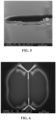
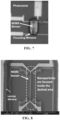
- nanoparticles/viruses are generated in the gas phase by Electrospray Ionization (ESI) and then deposited onto a chip patterned with photoresist ( Figure 5 ). Since photoresist is an insulator, the regions covered by it will quickly accumulate charge from the analyte ions arriving initially. The charged photoresist will then act as a highly-localized electrostatic lens that will direct the incoming particles to regions without photoresist.
- EI Electrospray Ionization
- the photoresist (or another suitable insulating material) covers around the NEMS to form a window above the NEMS plane as shown in Figure 5 and 6 , then the analyte particles can effectively be focused on the NEMS device as shown in Figures 7, 8 , 9, 10 , 11, 12 , 13 and 14 .
- the hydrocarbon chain length in the lipid part of the virion and the number of spike proteins are variable, which will cause a spread in the mass of SARS-CoV-2.
- one of the strategies of the present invention is to measure and identify via the nucleocapsid part of the virus which has a more specific structure.
- the nucleocapsid is obtained by treating the entire virion with a low-molecular weight, mild detergent (so as not to disrupt the core, but to dissolve the lipid shell).
- a centrifugation step for pelleting the cells and mucins will be performed first. Introducing a release agent at this stage will facilitate the dissociation of the virions from the cells. The supernatant-rich with background proteins at this stage- will then be buffer exchanged into 10mM ammonium acetate, which is the optimal solution for ESI process.
- the buffer exchange step will be performed by centrifugal filters with 100kDa molecular weight cutoff, so the majority of the proteins will be separated away from the virus samples.
- the processed sample will then be used in our NEMS Mass Spectrometer: a large number of hits at the nucleocapsid mass will translate into a positive identification.
- the proposed invention can similarly be used on processed or natural samples of other viruses, nanoparticles and proteins for the diagnosis of diseases, the characterization of samples e.g. for biomedical screening or pollution monitoring etc.
Landscapes
- Life Sciences & Earth Sciences (AREA)
- Physics & Mathematics (AREA)
- Health & Medical Sciences (AREA)
- Chemical & Material Sciences (AREA)
- Analytical Chemistry (AREA)
- Engineering & Computer Science (AREA)
- General Physics & Mathematics (AREA)
- Immunology (AREA)
- Molecular Biology (AREA)
- Biochemistry (AREA)
- General Health & Medical Sciences (AREA)
- Pathology (AREA)
- Bioinformatics & Computational Biology (AREA)
- Biomedical Technology (AREA)
- Acoustics & Sound (AREA)
- Urology & Nephrology (AREA)
- Hematology (AREA)
- Bioinformatics & Cheminformatics (AREA)
- Cell Biology (AREA)
- Proteomics, Peptides & Aminoacids (AREA)
- Biotechnology (AREA)
- Biophysics (AREA)
- Spectroscopy & Molecular Physics (AREA)
- Microbiology (AREA)
- Dispersion Chemistry (AREA)
- Food Science & Technology (AREA)
- Medicinal Chemistry (AREA)
- Other Investigation Or Analysis Of Materials By Electrical Means (AREA)
- Investigating Or Analysing Biological Materials (AREA)
Claims (25)
- Vorrichtung zur Bestimmung der Masse einzelner Nanopartikel, Viren und Proteine in Suspension oder in Lösung mit hoher Sammeleffizienz, dadurch gekennzeichnet, dass sie umfasst:- eine erste Vorrichtung (1) zur Erzeugung von geladenen Teilchen von Interesse in der Gasphase, wobei die erste Vorrichtung (1) eine Ionisationsquelle ist,- eine zweite Vorrichtung zur Bestimmung der Masse des Partikels durch eine Frequenzmessung, die mindestens einen gravimetrischen Detektor (4) umfasst, der auf einem Chip hergestellt ist,- eine dritte Vorrichtung, die auf demselben Chip wie die zweite Vorrichtung hergestellt ist, wobei die dritte Vorrichtung eine Isolierschicht (3) ist, die die zweite Vorrichtung umgibt und mindestens eine Öffnung (13) enthält, die mit der zweiten Vorrichtung ausgerichtet ist, um den Großteil der einfallenden geladenen Teilchen auf die zweite Vorrichtung zu fokussieren und zu leiten, indem sie einen Teil der einfallenden Ladungen auf sich selbst akkumuliert, um als elektrostatische Linse zu wirken.
- Vorrichtung nach Anspruch 1, dadurch gekennzeichnet, dass sie ferner eine separate elektrostatische Linse (12) im freien Raum zwischen der ersten Vorrichtung (1) und der dritten Vorrichtung zum Grobfokussieren der geladenen Teilchen und zum Abschirmen der zweiten Vorrichtung vor nachteiligen Einflüssen der ersten Vorrichtung (1) umfasst.
- Vorrichtung nach Anspruch 1, dadurch gekennzeichnet, dass die erste Vorrichtung (1) eine Elektrospray-Ionisationsquelle mit einem Spitzenradius ist, der klein genug ist, um in einer Niedervakuumkammer, in der die erste Vorrichtung untergebracht ist, aufrechtzuerhalten und in diese hinein zu elektrosprayen.
- Vorrichtung nach Anspruch 3, dadurch gekennzeichnet, dass die erste Vorrichtung ausgewählt ist aus Elektrospray-Ionisation, elektrohydrodynamischer Ionisation, Matrix-unterstützter Laser-Desorptionsionisation (MALDI), Laser-induzierter akustischer Desorption (LIAD), Ultraschallvernebler, mikrowelleninduzierter Vernebelungsvorrichtung, Mikrokapillar-Array-Vernebler, Oberflächenwellenvernebler.
- Vorrichtung nach Anspruch 3, dadurch gekennzeichnet, dass die erste Vorrichtung (1) durch Feldemission oder Koronaentladung als Hilfstechnik ergänzt ist, um zusätzliche Ladungen auf die Tröpfchen einzubringen.
- Vorrichtung nach Anspruch 1, dadurch gekennzeichnet, dass die zweite Vorrichtung und die dritte Vorrichtung in einer Hochvakuum- oder Ultrahochvakuumkammer angeordnet sind.
- Vorrichtung nach Anspruch 1, dadurch gekennzeichnet, dass der gravimetrische Detektor aus Nanoelektromechanischen Systemen, Mikroelektromechanischen Systemen, Quarzkristall-Mikrowaagen, Oberflächenakustikresonatoren, Volumenakustikresonatoren, Aufpralldetektoren oder Resonanzmikrowellendetektoren ausgewählt ist.
- Vorrichtung nach Anspruch 1, dadurch gekennzeichnet, dass die dritte Vorrichtung auf einer Schicht (7) ausgebildet ist, die sich direkt auf einem Substrat (5) befindet, das Teil des Chips ist, der die zweite Vorrichtung enthält.
- Vorrichtung nach Anspruch 8, dadurch gekennzeichnet, dass die Schicht (7) aus einem beliebigen ausreichend isolierenden Material besteht.
- Vorrichtung nach Anspruch 9, dadurch gekennzeichnet, dass die Schicht (7) aus Polymeren, Fotolacken oder Dielektrika besteht.
- Vorrichtung nach Anspruch 10, dadurch gekennzeichnet, dass die Schicht (7) aus Siliziumdioxid oder Siliziumnitrid besteht.
- Vorrichtung nach Anspruch 1, dadurch gekennzeichnet, dass die dritte Vorrichtung eine Dicke von 20 nm bis 1 mm aufweist, so dass die auf der dritten Vorrichtung aufgeladenen Ladungen nicht schnell neutralisiert werden.
- Vorrichtung zur Bestimmung der Masse einzelner Nanopartikel, Viren und Proteine in Suspension oder Lösung mit hoher Sammeleffizienz, gemäß Anspruch 1, dadurch gekennzeichnet, dass- die erste Vorrichtung (1) eine Elektrospray-Ionisationsquelle zum Elektrosprayen eines Fluids ist, um geladene Tröpfchen zu erzeugen, die die Analytpartikel enthalten, und um einen geladenen Fluss zu erhalten, der mindestens die Partikel umfasst,- die zweite Vorrichtung mindestens einen gravimetrischen Detektor (4) umfasst, der quer zur Elektrospray-Ionisationsquelle angeordnet ist und aus einer Schicht (7) hergestellt ist, die auch die dritte Vorrichtung trägt,- die dritte Vorrichtung die Isolierschicht (3) ist, die den Rest des Chips umgibt, wobei die Isolierschicht (3) so konfiguriert ist, dass sie angesammelte Ladungen (2) hält, die von der ersten Vorrichtung (1) abgeschieden und kontinuierlich aufgefüllt werden, wobei die Öffnung (13) dazu dient, einen elektrostatischen Linseneffekt zu erzielen,wobei die Vorrichtung ferner ein Substrat (5) umfasst, das Teil des Chips ist und sowohl die Isolierschicht (3) mit der Öffnung (13) als auch den gravimetrischen Detektor (4) hält.
- Vorrichtung nach Anspruch 13, dadurch gekennzeichnet, dass die Schicht (7) aus einem anderen Material als dem Material des Substrats (5) besteht oder aus dem gleichen Material wie das Substrat (5) hergestellt ist.
- Vorrichtung nach Anspruch 13, dadurch gekennzeichnet, dass der gravimetrische Detektor (4), die Schicht (7) und das Substrat (5) allein oder in Kombination aus vielen verschiedenen Materialschichten gebildet sind.
- Vorrichtung nach Anspruch 15, dadurch gekennzeichnet, dass der gravimetrische Detektor (4), die Schicht (7) und das Substrat (5) allein oder in Kombination aus Silizium-auf-Isolator gebildet sind.
- Vorrichtung nach Anspruch 13, dadurch gekennzeichnet, dass der Chip auf einer Plattform (6) sitzt, die mechanische Unterstützung bietet und die Form einer Leiterplatte haben kann, um den gravimetrischen Detektor (4) mit externen elektronischen Instrumenten zu verbinden.
- Vorrichtung zur Bestimmung der Masse einzelner Nanopartikel, Viren und Proteine in Suspension oder in Lösung mit hoher Sammeleffizienz, gemäß Anspruch 13, dadurch gekennzeichnet, dass die Tröpfchenbildung und Fokussierung durch Hüllgas (10) erleichtert wird, das durch einen kreisförmigen und vorzugsweise geneigten Schlitz konzentrisch zur Elektrospray-Ionisationsquelle entweder nahezu parallel oder konzentrisch zur Elektrospray-Richtung strömt, wobei die Elektrospray-Ionisationsquelle und/oder eine Ladungserzeugungsquelle (8) Ladungen (2) ablegen und kontinuierlich auffüllen, die auf der Isolierschicht (3) mit der Öffnung (13) gehalten werden, um einen elektrostatischen Linseneffekt zu erzielen.
wobei die Vorrichtung ferner umfasst:- eine Linse (12), die den gravimetrischen Detektor (4) vor nachteiligen Einflüssen der Elektrospray-Ionisationsquelle (1) abschirmt und eine zusätzliche elektrostatische Linsenwirkung für Ionen bereitstellen kann und entweder aus einem einzelnen Leiter oder einer Anordnung mehrerer Leiterelektroden besteht, wobei das Trocknungsgas (11) über und/oder unter der Linse (12) strömt, um die Verdampfung der Tröpfchen zu erleichtern, und- eine Spannungsquelle (9), die Spannung entweder direkt oder über eine Trägerplattform (6) des Chips an ein Substrat (5) anlegt, wobei der gravimetrische Detektor (4) über der Elektrospray-Ionisationsquelle, die die erste Vorrichtung (1) ist, und der Öffnung der Linse (12) angeordnet ist. - Vorrichtung nach Anspruch 18, dadurch gekennzeichnet, dass der Chip ein Mikrochip ist und auf der Plattform (6) sitzt, die mechanische Unterstützung bietet und die Form einer Leiterplatte haben kann, um den gravimetrischen Detektor mit externen elektronischen Instrumenten zu verbinden.
- Vorrichtung nach Anspruch 18, dadurch gekennzeichnet, dass die Linse 12 nahe an der Elektrospray-Ionisationsquelle 1 angeordnet ist, um ein Abschneiden interessanter Partikel zu vermeiden.
- Vorrichtung nach Anspruch 18, dadurch gekennzeichnet, dass die Linse 12 als zusätzliche elektrostatische Linse ausgebildet sein kann, die mit einer Spannungsquelle verbunden ist, um die Ionen grob auf den Chip zu fokussieren.
- Vorrichtung zur Bestimmung der Masse einzelner Nanopartikel, Viren und Proteine in Suspension oder in Lösung mit hoher Sammeleffizienz, gemäß Anspruch 13, dadurch gekennzeichnet, dass sie ferner eine Plattform (6) mit einer isolierenden Oberseite und einem vertieften Abschnitt umfasst, in den ein gravimetrischer Detektor (4) eingesetzt werden kann, wobei sowohl die Plattform (6) als auch die Isolierschicht (3) so konfiguriert sind, dass sie angesammelte Ladungen (2) aufnehmen, die von der ersten Vorrichtung (1) abgeschieden und kontinuierlich wieder aufgefüllt werden, mit einer Öffnung (13) zum Erzeugen eines elektrostatischen Linseneffekts.
- Vorrichtung nach Anspruch 22, dadurch gekennzeichnet, dass der Chip auf der Plattform (6) mit einer Aussparung angeordnet ist, die mechanische Abstützung bietet und die Form einer Leiterplatte haben kann, um den gravimetrischen Detektor (4) mit externen elektronischen Instrumenten zu verbinden.
- Vorrichtung nach Anspruch 22, dadurch gekennzeichnet, dass der Spalt zwischen der Plattform (6) und der Isolierschicht (3) mit einem isolierenden Füllmaterial gefüllt ist.
- Vorrichtung nach Anspruch 1, wobei die zweite Vorrichtung eine Anordnung von gravimetrischen Sensoren ist und die dritte Vorrichtung mehrere Öffnungen aufweist, die mit den Sensoren in der Anordnung ausgerichtet sind.
Applications Claiming Priority (3)
| Application Number | Priority Date | Filing Date | Title |
|---|---|---|---|
| US202063055917P | 2020-07-24 | 2020-07-24 | |
| US17/227,306 US20210319996A1 (en) | 2020-04-10 | 2021-04-10 | Device for obtaining the mass of single nanoparticles, viruses and proteins in suspension or in solution with high-collection efficiency |
| PCT/TR2021/050363 WO2022019855A1 (en) | 2020-07-24 | 2021-04-20 | Device for obtaining the mass of single nanoparticles, viruses and proteins in suspension or in solution with high-collection efficiency |
Publications (3)
| Publication Number | Publication Date |
|---|---|
| EP3970183A1 EP3970183A1 (de) | 2022-03-23 |
| EP3970183A4 EP3970183A4 (de) | 2022-08-10 |
| EP3970183B1 true EP3970183B1 (de) | 2025-07-09 |
Family
ID=79729672
Family Applications (1)
| Application Number | Title | Priority Date | Filing Date |
|---|---|---|---|
| EP21770110.1A Active EP3970183B1 (de) | 2020-07-24 | 2021-04-20 | Vorrichtung zur gewinnung der masse einzelner nanopartikel, viren und proteine in suspension oder in lösung mit hohem sammeleffizienz |
Country Status (2)
| Country | Link |
|---|---|
| EP (1) | EP3970183B1 (de) |
| WO (1) | WO2022019855A1 (de) |
Family Cites Families (6)
| Publication number | Priority date | Publication date | Assignee | Title |
|---|---|---|---|---|
| WO2011060369A1 (en) * | 2009-11-13 | 2011-05-19 | Goodlett David R | Ions generated by surface acoustic wave device detected by mass spectrometry |
| US8119977B2 (en) * | 2010-01-29 | 2012-02-21 | Pusan National University Industry-University Cooperation Foundation | Aerodynamic lens capable of focusing nanoparticles in a wide range |
| US9121823B2 (en) * | 2010-02-19 | 2015-09-01 | The Trustees Of The University Of Pennsylvania | High-resolution analysis devices and related methods |
| FR2979705B1 (fr) * | 2011-09-05 | 2014-05-09 | Commissariat Energie Atomique | Procede et dispositif d'estimation d'un parametre de masse moleculaire dans un echantillon |
| FR3003083B1 (fr) | 2013-03-11 | 2015-04-10 | Commissariat Energie Atomique | Dispositif de determination de la masse d'une particule en suspension ou en solution dans un fluide |
| CN110718442B (zh) * | 2015-01-23 | 2022-08-16 | 加州理工学院 | 整合的混合nems质谱测定法 |
-
2021
- 2021-04-20 EP EP21770110.1A patent/EP3970183B1/de active Active
- 2021-04-20 WO PCT/TR2021/050363 patent/WO2022019855A1/en not_active Ceased
Also Published As
| Publication number | Publication date |
|---|---|
| WO2022019855A1 (en) | 2022-01-27 |
| EP3970183A1 (de) | 2022-03-23 |
| EP3970183A4 (de) | 2022-08-10 |
Similar Documents
| Publication | Publication Date | Title |
|---|---|---|
| Keifer et al. | Single‐molecule mass spectrometry | |
| Todd et al. | Implementation of a charge-sensitive amplifier without a feedback resistor for charge detection mass spectrometry reduces noise and enables detection of individual ions carrying a single charge | |
| US6906322B2 (en) | Charged particle source with droplet control for mass spectrometry | |
| US8481922B2 (en) | Membrane for holding samples for use with surface ionization technology | |
| KR101465502B1 (ko) | 정전기 이온 트랩 | |
| US6504149B2 (en) | Apparatus and method for desolvating and focussing ions for introduction into a mass spectrometer | |
| US7078679B2 (en) | Inductive detection for mass spectrometry | |
| JP6352004B2 (ja) | 懸濁液又は溶液における粒子の質量測定装置 | |
| JP2019220477A (ja) | 出口における低気体流での低質量対電荷比イオンの効率的移送のためのイオンファンネル | |
| JP6593548B2 (ja) | 質量分析装置及びイオン検出装置 | |
| JP2010518378A (ja) | 質量分光計のための微分移動度分光計プレフィルタ | |
| JPH10512996A (ja) | 小型質量フィルタ | |
| JP2007266007A (ja) | 個別粒子を生成する方法及び機器 | |
| US11842891B2 (en) | Ion detector | |
| CN108695135B (zh) | 用于从气溶胶颗粒生成元素离子的离子源和方法 | |
| US7312444B1 (en) | Atmosperic pressure quadrupole analyzer | |
| Todd et al. | Dramatic improvement in sensitivity with pulsed mode charge detection mass spectrometry | |
| CN104380089A (zh) | 一种用于质谱仪器的改进接口 | |
| Szyszka et al. | MEMS quadrupole mass spectrometer | |
| Lai et al. | Advances in single particle mass analysis | |
| US20210319996A1 (en) | Device for obtaining the mass of single nanoparticles, viruses and proteins in suspension or in solution with high-collection efficiency | |
| EP3970183B1 (de) | Vorrichtung zur gewinnung der masse einzelner nanopartikel, viren und proteine in suspension oder in lösung mit hohem sammeleffizienz | |
| Peng et al. | Optical detection methods for mass spectrometry of macroions | |
| US7750312B2 (en) | Method and apparatus for generating ions for mass analysis | |
| JP2012505495A (ja) | 質量弁別器 |
Legal Events
| Date | Code | Title | Description |
|---|---|---|---|
| STAA | Information on the status of an ep patent application or granted ep patent |
Free format text: STATUS: UNKNOWN |
|
| STAA | Information on the status of an ep patent application or granted ep patent |
Free format text: STATUS: THE INTERNATIONAL PUBLICATION HAS BEEN MADE |
|
| PUAI | Public reference made under article 153(3) epc to a published international application that has entered the european phase |
Free format text: ORIGINAL CODE: 0009012 |
|
| STAA | Information on the status of an ep patent application or granted ep patent |
Free format text: STATUS: REQUEST FOR EXAMINATION WAS MADE |
|
| 17P | Request for examination filed |
Effective date: 20210930 |
|
| AK | Designated contracting states |
Kind code of ref document: A1 Designated state(s): AL AT BE BG CH CY CZ DE DK EE ES FI FR GB GR HR HU IE IS IT LI LT LU LV MC MK MT NL NO PL PT RO RS SE SI SK SM TR |
|
| A4 | Supplementary search report drawn up and despatched |
Effective date: 20220711 |
|
| RIC1 | Information provided on ipc code assigned before grant |
Ipc: G01N 29/036 20060101ALI20220705BHEP Ipc: G01N 33/68 20060101ALI20220705BHEP Ipc: G01G 3/16 20060101ALI20220705BHEP Ipc: G01N 33/543 20060101ALI20220705BHEP Ipc: G01N 15/10 20060101ALI20220705BHEP Ipc: G01N 29/02 20060101ALI20220705BHEP Ipc: H01J 49/34 20060101AFI20220705BHEP |
|
| DAV | Request for validation of the european patent (deleted) | ||
| DAX | Request for extension of the european patent (deleted) | ||
| STAA | Information on the status of an ep patent application or granted ep patent |
Free format text: STATUS: EXAMINATION IS IN PROGRESS |
|
| 17Q | First examination report despatched |
Effective date: 20240229 |
|
| GRAP | Despatch of communication of intention to grant a patent |
Free format text: ORIGINAL CODE: EPIDOSNIGR1 |
|
| STAA | Information on the status of an ep patent application or granted ep patent |
Free format text: STATUS: GRANT OF PATENT IS INTENDED |
|
| INTG | Intention to grant announced |
Effective date: 20250207 |
|
| RIN1 | Information on inventor provided before grant (corrected) |
Inventor name: PISHEH, HADI SEDAGHAT Inventor name: ALKHALED, MOHAMMED Inventor name: ERDOGAN, RAMAZAN TUFAN Inventor name: HANAY, MEHMET SELIM |
|
| GRAS | Grant fee paid |
Free format text: ORIGINAL CODE: EPIDOSNIGR3 |
|
| GRAA | (expected) grant |
Free format text: ORIGINAL CODE: 0009210 |
|
| STAA | Information on the status of an ep patent application or granted ep patent |
Free format text: STATUS: THE PATENT HAS BEEN GRANTED |
|
| AK | Designated contracting states |
Kind code of ref document: B1 Designated state(s): AL AT BE BG CH CY CZ DE DK EE ES FI FR GB GR HR HU IE IS IT LI LT LU LV MC MK MT NL NO PL PT RO RS SE SI SK SM TR |
|
| REG | Reference to a national code |
Ref country code: GB Ref legal event code: FG4D |
|
| REG | Reference to a national code |
Ref country code: CH Ref legal event code: EP |
|
| REG | Reference to a national code |
Ref country code: IE Ref legal event code: FG4D |
|
| REG | Reference to a national code |
Ref country code: DE Ref legal event code: R096 Ref document number: 602021033842 Country of ref document: DE |
|
| REG | Reference to a national code |
Ref country code: NL Ref legal event code: MP Effective date: 20250709 |
|
| PG25 | Lapsed in a contracting state [announced via postgrant information from national office to epo] |
Ref country code: PT Free format text: LAPSE BECAUSE OF FAILURE TO SUBMIT A TRANSLATION OF THE DESCRIPTION OR TO PAY THE FEE WITHIN THE PRESCRIBED TIME-LIMIT Effective date: 20251110 |
|
| PG25 | Lapsed in a contracting state [announced via postgrant information from national office to epo] |
Ref country code: NL Free format text: LAPSE BECAUSE OF FAILURE TO SUBMIT A TRANSLATION OF THE DESCRIPTION OR TO PAY THE FEE WITHIN THE PRESCRIBED TIME-LIMIT Effective date: 20250709 |
|
| REG | Reference to a national code |
Ref country code: AT Ref legal event code: MK05 Ref document number: 1812719 Country of ref document: AT Kind code of ref document: T Effective date: 20250709 |
|
| PG25 | Lapsed in a contracting state [announced via postgrant information from national office to epo] |
Ref country code: IS Free format text: LAPSE BECAUSE OF FAILURE TO SUBMIT A TRANSLATION OF THE DESCRIPTION OR TO PAY THE FEE WITHIN THE PRESCRIBED TIME-LIMIT Effective date: 20251109 |
|
| PG25 | Lapsed in a contracting state [announced via postgrant information from national office to epo] |
Ref country code: NO Free format text: LAPSE BECAUSE OF FAILURE TO SUBMIT A TRANSLATION OF THE DESCRIPTION OR TO PAY THE FEE WITHIN THE PRESCRIBED TIME-LIMIT Effective date: 20251009 |
|
| REG | Reference to a national code |
Ref country code: LT Ref legal event code: MG9D |
|
| PG25 | Lapsed in a contracting state [announced via postgrant information from national office to epo] |
Ref country code: AT Free format text: LAPSE BECAUSE OF FAILURE TO SUBMIT A TRANSLATION OF THE DESCRIPTION OR TO PAY THE FEE WITHIN THE PRESCRIBED TIME-LIMIT Effective date: 20250709 |
|
| PG25 | Lapsed in a contracting state [announced via postgrant information from national office to epo] |
Ref country code: FI Free format text: LAPSE BECAUSE OF FAILURE TO SUBMIT A TRANSLATION OF THE DESCRIPTION OR TO PAY THE FEE WITHIN THE PRESCRIBED TIME-LIMIT Effective date: 20250709 |
|
| PG25 | Lapsed in a contracting state [announced via postgrant information from national office to epo] |
Ref country code: HR Free format text: LAPSE BECAUSE OF FAILURE TO SUBMIT A TRANSLATION OF THE DESCRIPTION OR TO PAY THE FEE WITHIN THE PRESCRIBED TIME-LIMIT Effective date: 20250709 |
|
| PG25 | Lapsed in a contracting state [announced via postgrant information from national office to epo] |
Ref country code: GR Free format text: LAPSE BECAUSE OF FAILURE TO SUBMIT A TRANSLATION OF THE DESCRIPTION OR TO PAY THE FEE WITHIN THE PRESCRIBED TIME-LIMIT Effective date: 20251010 |
|
| PG25 | Lapsed in a contracting state [announced via postgrant information from national office to epo] |
Ref country code: SE Free format text: LAPSE BECAUSE OF FAILURE TO SUBMIT A TRANSLATION OF THE DESCRIPTION OR TO PAY THE FEE WITHIN THE PRESCRIBED TIME-LIMIT Effective date: 20250709 |
|
| PG25 | Lapsed in a contracting state [announced via postgrant information from national office to epo] |
Ref country code: LV Free format text: LAPSE BECAUSE OF FAILURE TO SUBMIT A TRANSLATION OF THE DESCRIPTION OR TO PAY THE FEE WITHIN THE PRESCRIBED TIME-LIMIT Effective date: 20250709 |
|
| PG25 | Lapsed in a contracting state [announced via postgrant information from national office to epo] |
Ref country code: BG Free format text: LAPSE BECAUSE OF FAILURE TO SUBMIT A TRANSLATION OF THE DESCRIPTION OR TO PAY THE FEE WITHIN THE PRESCRIBED TIME-LIMIT Effective date: 20250709 Ref country code: PL Free format text: LAPSE BECAUSE OF FAILURE TO SUBMIT A TRANSLATION OF THE DESCRIPTION OR TO PAY THE FEE WITHIN THE PRESCRIBED TIME-LIMIT Effective date: 20250709 |
|
| PG25 | Lapsed in a contracting state [announced via postgrant information from national office to epo] |
Ref country code: RS Free format text: LAPSE BECAUSE OF FAILURE TO SUBMIT A TRANSLATION OF THE DESCRIPTION OR TO PAY THE FEE WITHIN THE PRESCRIBED TIME-LIMIT Effective date: 20251009 |
|
| PG25 | Lapsed in a contracting state [announced via postgrant information from national office to epo] |
Ref country code: ES Free format text: LAPSE BECAUSE OF FAILURE TO SUBMIT A TRANSLATION OF THE DESCRIPTION OR TO PAY THE FEE WITHIN THE PRESCRIBED TIME-LIMIT Effective date: 20250709 |
|
| PG25 | Lapsed in a contracting state [announced via postgrant information from national office to epo] |
Ref country code: SM Free format text: LAPSE BECAUSE OF FAILURE TO SUBMIT A TRANSLATION OF THE DESCRIPTION OR TO PAY THE FEE WITHIN THE PRESCRIBED TIME-LIMIT Effective date: 20250709 |
|
| PG25 | Lapsed in a contracting state [announced via postgrant information from national office to epo] |
Ref country code: DK Free format text: LAPSE BECAUSE OF FAILURE TO SUBMIT A TRANSLATION OF THE DESCRIPTION OR TO PAY THE FEE WITHIN THE PRESCRIBED TIME-LIMIT Effective date: 20250709 |
|
| PG25 | Lapsed in a contracting state [announced via postgrant information from national office to epo] |
Ref country code: IT Free format text: LAPSE BECAUSE OF FAILURE TO SUBMIT A TRANSLATION OF THE DESCRIPTION OR TO PAY THE FEE WITHIN THE PRESCRIBED TIME-LIMIT Effective date: 20250709 |
|
| PG25 | Lapsed in a contracting state [announced via postgrant information from national office to epo] |
Ref country code: CZ Free format text: LAPSE BECAUSE OF FAILURE TO SUBMIT A TRANSLATION OF THE DESCRIPTION OR TO PAY THE FEE WITHIN THE PRESCRIBED TIME-LIMIT Effective date: 20250709 |
|
| PG25 | Lapsed in a contracting state [announced via postgrant information from national office to epo] |
Ref country code: SK Free format text: LAPSE BECAUSE OF FAILURE TO SUBMIT A TRANSLATION OF THE DESCRIPTION OR TO PAY THE FEE WITHIN THE PRESCRIBED TIME-LIMIT Effective date: 20250709 Ref country code: EE Free format text: LAPSE BECAUSE OF FAILURE TO SUBMIT A TRANSLATION OF THE DESCRIPTION OR TO PAY THE FEE WITHIN THE PRESCRIBED TIME-LIMIT Effective date: 20250709 |