EP3970829A1 - Filtre à disque en fibre comprenant un moyen de formation de rainure pour former des rainures sur la surface d'une toile filtrante - Google Patents
Filtre à disque en fibre comprenant un moyen de formation de rainure pour former des rainures sur la surface d'une toile filtrante Download PDFInfo
- Publication number
- EP3970829A1 EP3970829A1 EP21733883.9A EP21733883A EP3970829A1 EP 3970829 A1 EP3970829 A1 EP 3970829A1 EP 21733883 A EP21733883 A EP 21733883A EP 3970829 A1 EP3970829 A1 EP 3970829A1
- Authority
- EP
- European Patent Office
- Prior art keywords
- filter
- filter cloth
- foreign substances
- discfilter
- fiber
- Prior art date
- Legal status (The legal status is an assumption and is not a legal conclusion. Google has not performed a legal analysis and makes no representation as to the accuracy of the status listed.)
- Granted
Links
Images






Classifications
-
- B—PERFORMING OPERATIONS; TRANSPORTING
- B01—PHYSICAL OR CHEMICAL PROCESSES OR APPARATUS IN GENERAL
- B01D—SEPARATION
- B01D33/00—Filters with filtering elements which move during the filtering operation
- B01D33/15—Filters with filtering elements which move during the filtering operation with rotary plane filtering surfaces
- B01D33/21—Filters with filtering elements which move during the filtering operation with rotary plane filtering surfaces with hollow filtering discs transversely mounted on a hollow rotary shaft
- B01D33/23—Construction of discs or component sectors thereof
-
- B—PERFORMING OPERATIONS; TRANSPORTING
- B01—PHYSICAL OR CHEMICAL PROCESSES OR APPARATUS IN GENERAL
- B01D—SEPARATION
- B01D37/00—Processes of filtration
- B01D37/02—Precoating the filter medium; Addition of filter aids to the liquid being filtered
-
- B—PERFORMING OPERATIONS; TRANSPORTING
- B01—PHYSICAL OR CHEMICAL PROCESSES OR APPARATUS IN GENERAL
- B01D—SEPARATION
- B01D33/00—Filters with filtering elements which move during the filtering operation
- B01D33/15—Filters with filtering elements which move during the filtering operation with rotary plane filtering surfaces
- B01D33/21—Filters with filtering elements which move during the filtering operation with rotary plane filtering surfaces with hollow filtering discs transversely mounted on a hollow rotary shaft
-
- B—PERFORMING OPERATIONS; TRANSPORTING
- B01—PHYSICAL OR CHEMICAL PROCESSES OR APPARATUS IN GENERAL
- B01D—SEPARATION
- B01D33/00—Filters with filtering elements which move during the filtering operation
- B01D33/44—Regenerating the filter material in the filter
-
- B—PERFORMING OPERATIONS; TRANSPORTING
- B01—PHYSICAL OR CHEMICAL PROCESSES OR APPARATUS IN GENERAL
- B01D—SEPARATION
- B01D33/00—Filters with filtering elements which move during the filtering operation
- B01D33/44—Regenerating the filter material in the filter
- B01D33/46—Regenerating the filter material in the filter by scrapers, brushes nozzles or the like acting on the cake-side of the filtering element
- B01D33/463—Regenerating the filter material in the filter by scrapers, brushes nozzles or the like acting on the cake-side of the filtering element nozzles
-
- B—PERFORMING OPERATIONS; TRANSPORTING
- B01—PHYSICAL OR CHEMICAL PROCESSES OR APPARATUS IN GENERAL
- B01D—SEPARATION
- B01D33/00—Filters with filtering elements which move during the filtering operation
- B01D33/44—Regenerating the filter material in the filter
- B01D33/46—Regenerating the filter material in the filter by scrapers, brushes nozzles or the like acting on the cake-side of the filtering element
- B01D33/466—Regenerating the filter material in the filter by scrapers, brushes nozzles or the like acting on the cake-side of the filtering element scrapers
-
- B—PERFORMING OPERATIONS; TRANSPORTING
- B01—PHYSICAL OR CHEMICAL PROCESSES OR APPARATUS IN GENERAL
- B01D—SEPARATION
- B01D33/00—Filters with filtering elements which move during the filtering operation
- B01D33/44—Regenerating the filter material in the filter
- B01D33/48—Regenerating the filter material in the filter by flushing, e.g. counter-current air-bumps
- B01D33/50—Regenerating the filter material in the filter by flushing, e.g. counter-current air-bumps with backwash arms, shoes or nozzles
- B01D33/503—Regenerating the filter material in the filter by flushing, e.g. counter-current air-bumps with backwash arms, shoes or nozzles the backwash arms, shoes acting on the cake side
-
- B—PERFORMING OPERATIONS; TRANSPORTING
- B01—PHYSICAL OR CHEMICAL PROCESSES OR APPARATUS IN GENERAL
- B01D—SEPARATION
- B01D33/00—Filters with filtering elements which move during the filtering operation
- B01D33/80—Accessories
- B01D33/801—Driving means, shaft packing systems or the like
-
- B—PERFORMING OPERATIONS; TRANSPORTING
- B01—PHYSICAL OR CHEMICAL PROCESSES OR APPARATUS IN GENERAL
- B01D—SEPARATION
- B01D2201/00—Details relating to filtering apparatus
- B01D2201/08—Regeneration of the filter
- B01D2201/081—Regeneration of the filter using nozzles or suction devices
- B01D2201/082—Suction devices placed on the cake side of the filtering element
Definitions
- the present disclosure relates to a fiber discfilter, and more particularly, to a fiber discfilter with a means of forming grooves on a surface of filter cloths, in which the fiber discfilter includes a groove forming means for forming the groove in the surface of the filter cloth having bristles, such that foreign substances in a deep part of the filter cloth as well as foreign substances on the surface of the filter cloth are uniformly captured through the groove formed in the surface of the filter cloth during a filtering process, thereby increasing the quantity of captured foreign substances and effectively removing the foreign substances captured in the deep part of the filter cloth during a cleaning process for regenerating the filter cloth.
- a fiber discfilter refers to a filter installed in a water channel or a water tub into which a liquid (hereinafter, referred to as 'inflow water') such as wastewater, dirty water, purified water, rainwater, or process water is introduced, and the fiber discfilter filters the inflow water by filtering out foreign substances contained in the inflow water.
- 'inflow water' a liquid
- the fiber discfilter includes a filter unit configured such that a plurality of filter segments each having front and rear surfaces on which filter cloths each having a surface with bristles are installed is installed on an outer portion of a drum. Foreign substances are filtered out by the bristles during a process in which the inflow water is introduced into the filter segments through the filter cloths. The treated water from which the foreign substances are removed is introduced into the drum from the filter segment and then discharged to a predetermined location.
- the fiber discfilter since the inflow water is filtered as the inflow water flows from the outside of the filter segment into the filter segment via the filter cloth, a large quantity of foreign substances is captured on an outer surface of the filter cloth that constitutes a surface of the filter segment.
- the entire surface of the filter cloth having the bristles is provided in the form of a flat surface, the foreign substances are concentratedly captured on the surface of the filter cloth. For this reason, a coating layer is formed on the surface of the filter cloth, and almost no foreign substance is captured in the deep part of the filter cloth.
- the coating layer formed as described above inhibits the foreign substances from entering the deep part of the bristles, and as a result, a very small quantity of foreign substances is captured in the deep part of the bristles or almost no foreign substance is captured.
- the inflow water cannot be smoothly introduced into the filter segment. For this reason, a filtering speed is decreased, filtering efficiency deteriorates, a water level in the water channel or the water tub is quickly raised, and a cleaning cycle is shortened.
- the fiber discfilter includes a cleaning device for removing the foreign substances captured in the filter cloth.
- the cleaning device there are used a spray-type cleaning device which removes foreign substances by spraying high-pressure water toward the filter cloth, and a suction-type cleaning device which sucks and removes foreign substances captured in the filter cloth.
- the spray-type cleaning device includes a spray nozzle disposed to be spaced apart from the surface of the filter cloth at a predetermined distance, and a pump connected to the spray nozzle and configured to pump the water to the spray nozzle.
- the suction-type cleaning device includes a suction holder having a slit-shaped suction port elongated with a rectangular structure, and a pump connected to the suction holder and configured to provide a suction force.
- the spray-type cleaning device and the suction-type cleaning device remove the foreign substances from the filter cloth merely by spraying water toward the surface of the filter cloth or sucking the foreign substances from the surface of the filter cloth, there is a problem in that the foreign substances captured in a deep part of the bristle cannot be smoothly removed.
- Patent Document 1 Korean Patent No. 10-1935748 (published on January 4, 2019 )
- An object to be achieved by the present disclosure is to provide a fiber discfilter including a groove forming means for forming a groove in a surface of a filter cloth, the fiber discfilter being configured such that foreign substances in a deep part of a filter cloth having bristles as well as foreign substances on a surface part of the filter cloth may be smoothly captured during a process of filtering inflow water, and all the foreign substances captured on the surface and in the deep part of the filter cloth may be smoothly removed during a cleaning process by a cleaning means.
- Another object to be achieved by the present disclosure is to provide a fiber discfilter including a groove forming means for forming a groove in a surface of a filter cloth, in which the filter cloth is not damaged during a process of forming a groove in a surface of a filter cloth having bristles.
- Still another object to be achieved by the present disclosure is to provide a fiber discfilter including a groove forming means for forming a groove in a surface of a filter cloth, in which a suction force of a suction holder constituting a cleaning means is prevented from deteriorating due to a groove formed in a filter cloth.
- a fiber discfilter including a groove forming means for forming a groove in a surface of a filter cloth includes: a filter unit configured such that a plurality of filter segments each having front and rear surfaces on which filter cloths each having a surface provided with bristles are installed is installed on an outer portion of a drum so that inflow water is filtered by being introduced into the filter segments while passing through the filter cloths; a cleaning means configured to remove foreign substances captured in the filter cloths; and a groove forming means disposed to be positioned at the periphery of the filter unit and having a plurality of protrusions configured to be inserted into the surface of the filter cloth and form grooves in the surface of the filter cloth when the filter unit rotates, such that foreign substances on the surface of the filter cloth and foreign substances in a deep part of the filter cloth are uniformly captured during a process of filtering the inflow water, and the foreign substances captured in the deep part of the filter cloth are exposed during a process of cleaning the filter cloth, such that the
- each of the protrusions may be a rigid protrusion with a fixed shape and a fixed size.
- the rigid protrusions may be formed in a triangular shape in which a width of an inner end thereof is larger than a width of an outer end thereof.
- each of the protrusions may be an elastic protrusion having a ball installed at an end of an elastically deformable stick.
- the plurality of protrusions may include a combination of two or more types of protrusions having different protruding lengths.
- the groove forming means may be configured separately from the cleaning means such that the protrusions are formed on a board fixedly installed on a support for fixing the cleaning means or fixedly installed on a separate structure.
- the protrusions of the groove forming means may be formed or installed directly on the cleaning means so as to be formed integrally with the cleaning means.
- the cleaning means may include a suction holder configured to remove the foreign substances on the filter cloth by sucking the foreign substances, in which the fiber discfilter further includes a blocking means positioned at a rear end of the cleaning means based on a rotation direction of the filter unit, and in which the blocking means has a plurality of blocking protrusions which is inserted into the respective grooves formed in the surface of the filter cloth by the groove forming means to block the grooves in order to reduce a loss of a suction force of the suction holder.
- the elastic sticks form the grooves while being deformed in accordance with the states of the bristles, thereby preventing damage to the filter cloth.
- the cleaning device includes the suction holder for removing the foreign substances by sucking the foreign substances and the blocking means is further provided at the rear end of the suction holder
- the blocking means closes the groove formed in the filter cloth from the portion behind the suction holder, such that the suction force of the suction holder may be prevented from being lost through the groove, thereby further improving efficiency in removing the foreign substances.
- FIG. 1 is a structural front view of a fiber discfilter according to an exemplary embodiment of the present disclosure
- FIG. 2 is a structural side view illustrating a state in which groove forming means having rigid protrusions according to the present disclosure are installed on supports for fixing suction holders and disposed at front and rear sides of a filter segment
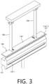
- FIG. 3 is a perspective view illustrating a state in which the groove forming means having the rigid protrusions according to the present disclosure is installed on the supports for fixing the suction holder
- FIG. 4 is a top plan view of the groove forming means having a board and the rigid protrusions
- FIG. 1 is a structural front view of a fiber discfilter according to an exemplary embodiment of the present disclosure
- FIG. 2 is a structural side view illustrating a state in which groove forming means having rigid protrusions according to the present disclosure are installed on supports for fixing suction holders and disposed at front and rear sides of a filter segment
- FIG. 3 is a perspective view illustrating a state in which the
- FIG. 5 is a structural side view illustrating a state in which elastic protrusions according to the present disclosure are formed integrally with the suction holders and disposed at the front and rear sides of the filter segment together with the suction holders
- FIG. 6 is a perspective view illustrating a state in which the elastic protrusions according to the present disclosure are formed integrally with the suction holder
- FIG. 7 is a top plan view illustrating a state in which the elastic protrusions according to the present disclosure are formed integrally with the suction holder
- FIG. 8 is a perspective view illustrating a state in which a blocking means according to the present disclosure is further installed at a lower end of the suction holder
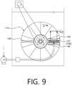
- FIG. 9 is a structural front view illustrating an installation position of the groove forming means in a fiber discfilter including a suction-type cleaning means
- FIG. 10 is a structural front view illustrating an installation position of the groove forming means in a fiber discfilter including a spray-type cleaning means
- FIG. 11 is a structural front view illustrating an installation position of the groove forming means in a fiber discfilter including a cleaning means implemented by a combination of the suction-type cleaning means and the spray-type cleaning means
- FIG. 12 is a front view illustrating a state in which a plurality of grooves is formed in a filter segment assembly by the groove forming means according to the present disclosure.
- a fiber discfilter according to the present disclosure includes a filter unit 110, a drive means 120, a cleaning means 130, and a groove forming means 140.
- the filter unit 110 includes a plurality of filter segments 111 provided on an outer portion of a drum 112.
- Filter cloths 113 which have surfaces on which bristles are disposed, are provided on front and rear surfaces of each of the filter segments 111, such that foreign substances contained in inflow water, which is introduced through the front and rear surfaces of the filter segment 111, are filtered out by the filter cloths 113, and treated water from which the foreign substances are removed is discharged into the drum 112.
- the plurality of filter segments 111 is distributed in a circumferential direction of the drum 112 on the outer portion of the drum 112.
- the plurality of filter segments 111 is disposed in the circumferential direction of the drum 112 so that lateral surfaces of the two adjacent filter segments 111 are in close contact with each other.
- a ring-shaped filter segment assembly which is configured by the plurality of filter segments 111 disposed and installed in the circumferential direction of the drum 112, is provided in plural, and the plurality of filter segment assemblies is installed to be spaced apart from one another at a predetermined interval in a longitudinal direction of the drum 112.
- the plurality of filter segments 111 is distributed in the circumferential direction and the longitudinal direction of the drum 112 and configured to be rotated together with the drum 112.
- the drive means 120 serves to rotate the drum 112 and includes a motor 121 and a power transmission mechanism 122 connecting the motor 121 and the drum 112.
- the power transmission mechanism 122 may include a belt or a chain.
- the cleaning means 130 are installed to be positioned at front and rear sides of the filter segment assembly installed on the drum 112.
- the cleaning means 130 may be configured as a spray-type cleaning device that removes foreign substances by separating the foreign substances captured by the filter cloths 113 by spraying water to the filter cloths 113 using a plurality of spray nozzles 132.
- the cleaning means 130 may be configured as a suction-type cleaning device that removes foreign substances by collecting the foreign substances, which are captured by the filter cloths 113, by means of vacuum suction using a suction holder 131.
- the filter unit 110, the drive means 120, and the cleaning means 130 may be configured to be identical to a filter unit, a drive means, and a cleaning means which are applied to a fiber discfilter already widely used, more detailed descriptions of the filter unit 110, the drive means 120, and the cleaning means 130 will be omitted.
- the groove forming means 140 serves to form grooves in a surface of the filter cloth 113 that has bristles.
- the groove forming means 140 has a plurality of protrusions 141 configured to be inserted into the surface of the filter cloth 113.
- the groove forming means 140 are disposed at the front and rear sides of the ring-shaped filter segment assembly and extend in a direction that traverses a part of the filter segment assembly, such that the groove forming means 140 are configured to form the plurality of grooves 114 in the surfaces of the filter cloths 113 when the filter unit 110 rotates.
- the protrusions 141 may be rigid protrusions 1411 with fixed shapes and fixed sizes and configured to form the grooves in the surface of the filter cloth 113 as the rigid protrusions 1411 are inserted into the surface of the filter cloth 113 that has the bristles.
- the rigid protrusion 1411 may be formed in a triangular shape in which a width W1 of an inner end thereof is larger than a width W2 of an outer end thereof so that the rigid protrusion 1411 more smoothly forms the groove by being inserted into the surface of the filter cloth 113 and a deep part of the filter cloth 113 is exposed more appropriately.
- the protrusion 141 may be an elastic protrusion 1412 including a ball 1414 installed at an end of an elastically deformable stick 1413.
- the elastic protrusion 1412 is configured to form the groove in the surface of the filter cloth 113 by being inserted into the surface of the filter cloth 113.
- the stick 1413 is made of spring steel or synthetic resin so as to be elastically deformable.
- the stick 1413 is bent when a relatively great force is applied due to tangling of the bristles or adhesion of the foreign substances during the process of forming the groove in the surface of the filter cloth 113, thereby preventing damage to the filter cloth 113.
- the ball 1414 is installed or formed at the end of the stick 1413 and has a relatively larger diameter than the stick 1413.
- the stick 1413 is bent in accordance with the state of the bristles during the process of forming the groove in the surface of the filter cloth 113, thereby preventing a great force from being applied to the bristles and thus preventing damage to the bristles.
- the ball 1414 having a relatively larger diameter than the stick 1413 is inserted into the surface of the filter cloth 113 and passes between the bristles by the rotation of the filter unit 110, thereby inducing separation and exposure of foreign substances captured in the deep part of the filter cloth 113.
- the plurality of protrusions 141 provided in the groove forming means 140 may include a combination of two or more types of protrusions 141 having different protruding lengths.
- FIG. 7 illustrates a configuration in which two types of elastic protrusions 1412 having different protruding lengths are combined.
- the plurality of protrusions 141 includes the combination of the two or more types of protrusions 141 having different protruding lengths as described above, it is possible to form the grooves having various depths at a time.
- the protrusion 141 may be formed or provided on a board 142 fixedly installed on supports 150 for supporting the cleaning means 130, or the protrusion 141 may be formed or provided on the board 142 fixedly installed on a separate structure.
- the protrusion 141 may be configured as a structure provided separately from or independently of the cleaning means 130, or the protrusion 141 may be formed or provided directly on the cleaning means 130 so that the protrusion 141 is provided integrally with the cleaning means 130.
- the board 142 has rectangular bolt through ports 1421 that elongate and extend in a direction orthogonal to the surface of the filter cloth 113, such that depths of the protrusions 141 inserted into the surface of the filter cloth 113 may be adjusted in accordance with the state of the filter cloth 113.
- angled brackets 151 which are bent in an L shape, are installed on the supports 150 or the structures on which the board 142 is fixedly installed, the board 142 is fixed by bolting in the state in which the board 142 is seated on the angled brackets 151, and the rectangular bolt through ports 1421 extending in the direction orthogonal to the surface of the filter cloth 113 are formed in the board 142. Therefore, the board 142 may be fixed to the angled brackets 151 by bolting in a state in which positions of the protrusions 141 are adjusted by moving the board 142 toward or away from the filter cloth 113. As a result, a manager may adjust the insertion depths of the protrusions 141 in accordance with the state of the filter cloth 113.
- the fiber discfilter including the groove forming means 140 configured as described above may further include a blocking means 160 configured to prevent efficiency in sucking foreign substances from deteriorating due to an inflow of outside air through the groove formed in the surface of the filter cloth 113.
- the blocking means 160 is restrictively applied only in the case in which the cleaning means 130 includes the suction holder 131.
- the blocking means 160 is disposed to be positioned at a rear end of the suction holder 131 based on a rotation direction D of the filter unit 110.
- the blocking means 160 may be fixedly installed on the suction holder 131 or fixedly installed on a separate bracket.
- the blocking means 160 includes a plurality of blocking protrusions 161 which are inserted into the grooves formed in the surface of the filter cloth 113 by the groove forming means 140, thereby blocking flow paths formed by the grooves.
- the blocking means 160 formed as described above closes the grooves formed in the filter cloth 113 from a portion behind the suction holder 131, thereby preventing a suction force of the suction holder 131 from being lost through the grooves during the process in which the suction holder 131 sucks the foreign substances captured in the filter cloth 113, and thus inducing smooth suction of the foreign substances.
- the fiber discfilter according to the present disclosure configured as described above is installed in a water channel or a water tub into which inflow water such as wastewater, dirty water, purified water, rainwater, or process water is introduced, and the fiber discfilter filters out foreign substances contained in the inflow water.
- inflow water such as wastewater, dirty water, purified water, rainwater, or process water
- the groove forming means 140 may be installed at the front end or the rear end of the cleaning means 130 based on the rotation direction D of the filter unit 110. Alternatively, the groove forming means 140 may be installed at any position as long as the groove forming means 140 may smoothly form the groove in the surface of the filter cloth 113 without interfering with peripheral structures.
- FIG. 9 illustrates a structure in which the groove forming means 140 is installed on at least one of the front end of the suction holder 131, the rear end of the suction holder 131, and any position irrelevant to the suction holder 131.
- FIG. 10 illustrates structure in which the groove forming means 140 is installed on at least one of the front end of the spray nozzle 132, the rear end of the spray nozzle 132, and any position irrelevant to the spray nozzle 132.
- FIG. 11 illustrates a structure in which the groove forming means 140 is installed on at least one of the front and rear ends of the suction holder 131, the front and rear ends of the spray nozzle 132, and any position.
- the groove forming means 140 according to the present disclosure may be freely installed without limitation to the installation position.
- the filter unit 110 may be rotated intermittently or consistently to always form the grooves in the surface of the filter cloth 113.
- the groove formed in the surface of the filter cloth 113 exposes the deep part of the filter cloth 113, thereby establishing an environment in which the foreign substances may be captured not only on the surface of the filter cloth 113, but also in the deep part of the filter cloth 113 during the filtering process of filtering the inflow water.
- a larger quantity of foreign substances may be captured by the single filtering process, and the cleaning cycle may be increased.
- the groove forming means 140 improves cleaning efficiency while forming the groove in the surface of the filter cloth 113 even during the process of cleaning the filter cloth 113.
- the protrusions 141 provided on the groove forming means 140 according to the present disclosure are always kept inserted into the surface of the filter cloth 113 regardless of the filtering process or the cleaning process. Therefore, when the filter unit 110 rotates to perform the cleaning process, the plurality of grooves 114 extending in the circumferential direction of the filter unit 110 is formed in the surface of the filter cloth 113 in accordance with the rotational operation of the filter unit 110.
- the plurality of grooves 114 formed in the surface of the filter cloth 113 exposes the foreign substances, which are captured in the deep part of the filter cloth 113, to the outside.
- the spray nozzle 132 constituting the cleaning means 130 sprays water or the suction holder 130 sucks the foreign substances, and as a result, not only the foreign substances on the surface of the filter cloth 113 may be removed, but also the foreign substances in the deep part may be effectively removed.
- the fiber discfilter according to the present disclosure forms the plurality of grooves in the surface of the filter cloth 113 using the groove forming means 140, such that the foreign substances in the deep part of the filter cloth 113 as well as the foreign substances on the surface of the filter cloth 113 may be uniformly captured during the filtering process.
- the present disclosure is a very useful invention because the quantity of captured foreign substances may be significantly increased, and all the foreign substances on the surface part of the filter cloth 113 and in the deep part of the filter cloth 113 may be smoothly removed during the cleaning process.
Landscapes
- Chemical & Material Sciences (AREA)
- Chemical Kinetics & Catalysis (AREA)
- Detail Structures Of Washing Machines And Dryers (AREA)
- Cleaning In General (AREA)
- Filtering Materials (AREA)
- Separation Using Semi-Permeable Membranes (AREA)
Applications Claiming Priority (2)
| Application Number | Priority Date | Filing Date | Title |
|---|---|---|---|
| KR1020200096657A KR102264455B1 (ko) | 2020-08-03 | 2020-08-03 | 여과포 표면에 홈을 형성하는 홈형성수단을 포함하는 섬유디스크필터 |
| PCT/KR2021/005220 WO2022030728A1 (fr) | 2020-08-03 | 2021-04-26 | Filtre à disque en fibre comprenant un moyen de formation de rainure pour former des rainures sur la surface d'une toile filtrante |
Publications (4)
| Publication Number | Publication Date |
|---|---|
| EP3970829A1 true EP3970829A1 (fr) | 2022-03-23 |
| EP3970829A4 EP3970829A4 (fr) | 2023-07-12 |
| EP3970829B1 EP3970829B1 (fr) | 2024-09-25 |
| EP3970829C0 EP3970829C0 (fr) | 2024-09-25 |
Family
ID=76376298
Family Applications (1)
| Application Number | Title | Priority Date | Filing Date |
|---|---|---|---|
| EP21733883.9A Active EP3970829B1 (fr) | 2020-08-03 | 2021-04-26 | Filtre à disque en fibre comprenant un moyen de formation de rainure pour former des rainures sur la surface d'une toile filtrante |
Country Status (5)
| Country | Link |
|---|---|
| US (1) | US20230277962A1 (fr) |
| EP (1) | EP3970829B1 (fr) |
| KR (2) | KR102264455B1 (fr) |
| ES (1) | ES2989456T3 (fr) |
| WO (1) | WO2022030728A1 (fr) |
Cited By (1)
| Publication number | Priority date | Publication date | Assignee | Title |
|---|---|---|---|---|
| DE102022118497A1 (de) | 2022-07-25 | 2024-01-25 | Mecana Umwelttechnik Gmbh | Vorrichtung zum Reinigen und/oder Absaugen von Polfasern für die Polstofffiltration |
Families Citing this family (6)
| Publication number | Priority date | Publication date | Assignee | Title |
|---|---|---|---|---|
| US12377372B2 (en) * | 2021-06-08 | 2025-08-05 | Greatpyr Resources Llc | Apparatus, systems, and processes employing wet/dry suction filter with chicaned suction head |
| KR102404899B1 (ko) * | 2021-07-27 | 2022-06-07 | 주식회사 그레넥스 | 섬유상 여과기의 역세정 흡입장치 |
| KR102451203B1 (ko) | 2021-09-17 | 2022-10-06 | 문연우 | 2단 수직식 흡입세척장치 및 이를 포함하는 섬유디스크필터 |
| KR102457922B1 (ko) | 2022-04-07 | 2022-10-24 | 주식회사 유천엔바이로 | 분리형 2단 수직식 흡입세척장치 및 이를 포함하는 섬유디스크필터 |
| KR102539786B1 (ko) * | 2022-07-28 | 2023-06-07 | (주)한성산업 | 오폐수용 섬유여과장치 |
| CN116216920B (zh) * | 2023-05-09 | 2023-08-18 | 广东景天环境科技股份有限公司 | 一种养殖废水处理设备 |
Family Cites Families (82)
| Publication number | Priority date | Publication date | Assignee | Title |
|---|---|---|---|---|
| US1980438A (en) * | 1934-11-13 | Suction cleaner | ||
| US963049A (en) * | 1910-07-05 | Vacuum Cleaner Company | Apparatus for removing dust. | |
| US3268942A (en) * | 1966-08-30 | Suction cleaning nozzle | ||
| US1529282A (en) * | 1920-10-20 | 1925-03-10 | Landers Frary & Clark | Vacuum-cleaner nozzle |
| US1833315A (en) * | 1923-12-21 | 1931-11-24 | Harry H Burhans | Filtering medium |
| US1859132A (en) * | 1928-11-20 | 1932-05-17 | Jorgen F H Fechtenburg | Suction comb |
| US1928944A (en) * | 1931-10-12 | 1933-10-03 | Hoover Co | Suction cleaner |
| US1936369A (en) * | 1933-01-13 | 1933-11-21 | Air Way Electric Appl Corp | Suction cleaner floor tool |
| GB473232A (en) * | 1936-03-21 | 1937-10-08 | Electrolux Ltd | Improvements in nozzles for vacuum cleaners |
| US2626419A (en) * | 1950-06-06 | 1953-01-27 | Landers Frary & Clark | Vacuum cleaner nozzle and combing tooth construction therefor |
| US2717409A (en) * | 1950-09-15 | 1955-09-13 | Herbert T Draudt | Vacuum cleaner nozzle |
| US2621798A (en) * | 1951-07-13 | 1952-12-16 | Aloysius C Kracklauer | Clean-out mechanism for filters and the like |
| US3019186A (en) * | 1957-12-12 | 1962-01-30 | Milton A Powers | Fluid filtering mediums and method of making the same |
| US3039122A (en) * | 1960-05-16 | 1962-06-19 | Clarence E Birdsall | Hydraulic suction head for cleaning water reservoirs |
| SE218448C1 (sv) * | 1962-04-11 | 1968-01-23 | Electrolux Ab | Dammsugningsverktyg |
| US3225379A (en) * | 1964-01-22 | 1965-12-28 | Rexair Inc | Rug tool |
| US3520012A (en) * | 1968-02-20 | 1970-07-14 | Hoover Co | Squeegee nozzle for wet pickup suction cleaner |
| US3538533A (en) * | 1969-06-16 | 1970-11-10 | John A Woods | Nap raising device |
| US3611473A (en) * | 1969-08-01 | 1971-10-12 | Phillip P Johnson | Vacuum cleaner attachment for shag rugs and the like |
| US3685089A (en) * | 1970-08-17 | 1972-08-22 | Nat Union Electric Corp | Shag rug tool |
| US3668735A (en) * | 1970-10-01 | 1972-06-13 | Fred W Dupea | Vacuum cleaner head for cleaning and combing shag carpeting |
| US3668734A (en) * | 1970-10-21 | 1972-06-13 | Health Mor Inc | Vacuum cleaner shag rug nozzle construction |
| US3708824A (en) * | 1971-01-22 | 1973-01-09 | S Holubinka | Suction-cleaning implement |
| US3745603A (en) * | 1971-05-10 | 1973-07-17 | F Bayless | Vacuum cleaner suction tool for cleaning deep pile shag rugs |
| US3733646A (en) * | 1971-06-14 | 1973-05-22 | G Mein | Vacuum cleaner head with shag rug rake |
| GB1323208A (en) * | 1971-07-27 | 1973-07-11 | Hamano T | Filter for removing such particles and miscellaneous dirt as contained in a fluid |
| US3745604A (en) * | 1971-09-03 | 1973-07-17 | Gen Signal Corp | Tool for cleaning and raking shag type rugs |
| US3795938A (en) * | 1971-10-08 | 1974-03-12 | Mc Nulty W | Vacuum cleaner attachment for shag rugs |
| US3740788A (en) * | 1971-10-29 | 1973-06-26 | K Kingston | Shag rug groomer |
| US3744082A (en) * | 1971-11-05 | 1973-07-10 | A Marshall | Vacuum cleaner and rake |
| BE793322A (fr) * | 1971-12-29 | 1973-04-16 | Mecafina Sa | Installation d'epuration mecanique et biologique d'eaux usees |
| US3783474A (en) * | 1972-07-03 | 1974-01-08 | Health Mor Inc | Shag rug attachment for suction cleaner nozzle |
| US3797066A (en) * | 1972-09-05 | 1974-03-19 | J Zaidan | Shag rug vacuum head |
| US3818540A (en) * | 1973-01-12 | 1974-06-25 | Health Mor Inc | Combined adjustable shag rug-power nozzle cleaner construction |
| US3838474A (en) * | 1973-02-26 | 1974-10-01 | Groom Ind Inc | Carpet grooming tools |
| US3825972A (en) * | 1973-04-23 | 1974-07-30 | Scott & Fetzer Co | Shag rug fluffer |
| US3913169A (en) * | 1973-10-26 | 1975-10-21 | Claude W Seymour | Rake device |
| US3857786A (en) * | 1973-10-29 | 1974-12-31 | L Wolf | Brushing accessory for spin filter |
| US4087879A (en) * | 1975-01-10 | 1978-05-09 | Forrest Spence | Shag rug brushing and object retrieving device |
| US3999244A (en) * | 1975-05-22 | 1976-12-28 | Century Tool Company | Shag rug rake |
| US3977847A (en) * | 1975-08-08 | 1976-08-31 | Brunswick Corporation | Filtration method and apparatus |
| US4042995A (en) * | 1976-05-24 | 1977-08-23 | Hyman Varon | Tool for removing animal hair from carpeting |
| US4143441A (en) * | 1977-01-10 | 1979-03-13 | National Union Electric Corporation | Vacuum cleaner nozzle |
| USD262671S (en) * | 1979-11-01 | 1982-01-19 | Groom Industries, Inc. | Carpet grooming tool |
| US4333205A (en) * | 1979-11-14 | 1982-06-08 | Robert E. Robbins | Vacuum cleaner with soil agitator and compressed air means |
| US4291430A (en) * | 1980-05-21 | 1981-09-29 | Ronald Hightower | Janitor's rake for removing staples imbedded in carpet |
| US4300261A (en) * | 1980-08-15 | 1981-11-17 | Robert E. Robbins | Vacuum cleaning apparatus with compressed air means |
| FI96281B (fi) | 1993-07-15 | 1996-02-29 | Ahlstroem Oy | Menetelmä ja laite meesalietteen saostamiseksi kiekkosuotimella |
| US5374360A (en) * | 1993-12-14 | 1994-12-20 | Aqua-Aerobic Systems, Inc. | Method and apparatus for cleaning a filter apparatus |
| USD364788S (en) * | 1994-07-11 | 1995-12-05 | Suddeth Leighton K | Grass carpet rake |
| DE19624483A1 (de) * | 1996-06-19 | 1998-01-02 | Mecana Umwelttechnik Ag | Filtertuch, Filtrierverfahren und Filtriervorrichtung für die Flüssigkeitsfiltration |
| USD389618S (en) * | 1996-10-15 | 1998-01-20 | Rosen Catherine B | Pet vacuum brush |
| US6421875B1 (en) * | 2000-06-12 | 2002-07-23 | Pro-Team, Inc. | Vortex floor tool |
| BR0100425C2 (pt) * | 2001-01-12 | 2003-12-02 | Daniel Villares Lenz Cesar | Filtro autolimpante |
| US20020166512A1 (en) * | 2001-05-11 | 2002-11-14 | Corbett Austin Kit | Utility nozzle with comb apparatus for grooming pets |
| EP1392108B1 (fr) * | 2001-05-17 | 2007-10-17 | Hair Patrol LLC | Outil de toilettage a aspiration |
| AUPS131002A0 (en) * | 2002-03-25 | 2002-05-09 | Amos, Pamela Louise | A cleaning method and means |
| US7678284B2 (en) * | 2003-01-09 | 2010-03-16 | Grouse Mountain, Inc. | Tertiary filter |
| US8117714B2 (en) * | 2005-03-09 | 2012-02-21 | Bissell Homecare, Inc. | Vacuum cleaner with hair collection element |
| US8048296B2 (en) * | 2006-10-20 | 2011-11-01 | Jay Stevens | Filtering device for liquid filtration |
| WO2008157707A2 (fr) * | 2007-06-20 | 2008-12-24 | Parkson Corporation | Filtre modulaire et ensemble de tête à vide pour appareil de filtration |
| EP2182831B9 (fr) * | 2007-08-07 | 2014-04-16 | Bissell Homecare, Inc. | Outil de traitement de surface |
| KR100876198B1 (ko) * | 2008-07-11 | 2008-12-31 | 주식회사 유천엔바이로 | 다중세척장치가 적용된 여과장치 |
| US20120080370A1 (en) * | 2010-10-05 | 2012-04-05 | Chi-Chang Kuo | Water Treatment Apparatus |
| US8778174B2 (en) * | 2010-10-15 | 2014-07-15 | Alfa Laval Ashbrook Simon-Hartley Inc. | Methods and apparatus for treating water and wastewater employing a cloth disk filter |
| US9402523B2 (en) * | 2011-03-14 | 2016-08-02 | Roy Studebaker | Rotary surface cleaning tool |
| WO2013032085A1 (fr) * | 2011-08-31 | 2013-03-07 | (주)에이앤티 | Appareil d'aspiration pour filtre fibreux et dispositif de filtration l'utilisant |
| US8852445B2 (en) * | 2011-10-28 | 2014-10-07 | Alfa Laval Ashbrook Simon-Hartley, Inc | Methods and apparatus for treating water and wastewater employing a cloth disk filter |
| US10905981B2 (en) * | 2011-10-28 | 2021-02-02 | Alfa Laval Corporate Ab | Methods and apparatus for treating water and wastewater employing a cloth filter |
| KR101177369B1 (ko) * | 2012-04-26 | 2012-08-27 | (주) 에이앤티 | 섬유상 여과기의 역세정 흡입장치 및 이를 이용한 섬유상 여과기 |
| JP6158581B2 (ja) * | 2013-04-30 | 2017-07-05 | 富士フィルター工業株式会社 | 濾過装置 |
| SE538959C2 (en) * | 2015-07-09 | 2017-03-07 | Valmet Oy | Agitator system for a disc filter |
| WO2017092777A1 (fr) * | 2015-12-03 | 2017-06-08 | Kronos International, Inc. | Procédé et dispositif de filtration solide-liquide améliorée de gâteaux de filtre |
| KR101728525B1 (ko) * | 2016-07-20 | 2017-04-19 | 최규연 | 하수 처리 장치 |
| KR101791863B1 (ko) * | 2017-04-25 | 2017-11-01 | 주식회사 그레넥스 | 섬유상 여과기의 역세정 흡입 장치 |
| US10195549B1 (en) | 2017-11-21 | 2019-02-05 | Aqua-Aerobic Systems, Inc. | Backwash shoe method and apparatus that increases effective surface area of cloth filter media |
| CN108479162A (zh) | 2018-05-29 | 2018-09-04 | 江苏三辉环保科技有限公司 | 一种全浸式纤维转盘微过滤器 |
| KR101935748B1 (ko) | 2018-08-24 | 2019-01-04 | 주식회사 유천엔바이로 | 다절 링크를 구비한 섬유 디스크 필터 여과 장치 |
| KR102183820B1 (ko) * | 2020-03-10 | 2020-11-30 | 주식회사 그레넥스 | 섬유상 여과기의 역세정 흡입장치 |
| US12377372B2 (en) * | 2021-06-08 | 2025-08-05 | Greatpyr Resources Llc | Apparatus, systems, and processes employing wet/dry suction filter with chicaned suction head |
| KR102404899B1 (ko) * | 2021-07-27 | 2022-06-07 | 주식회사 그레넥스 | 섬유상 여과기의 역세정 흡입장치 |
| USD1055441S1 (en) * | 2024-03-05 | 2024-12-24 | Xueji Liu | Hair remover |
-
2020
- 2020-08-03 KR KR1020200096657A patent/KR102264455B1/ko active Active
- 2020-12-29 KR KR1020200185914A patent/KR102476876B1/ko active Active
-
2021
- 2021-04-26 EP EP21733883.9A patent/EP3970829B1/fr active Active
- 2021-04-26 US US17/927,394 patent/US20230277962A1/en not_active Abandoned
- 2021-04-26 WO PCT/KR2021/005220 patent/WO2022030728A1/fr not_active Ceased
- 2021-04-26 ES ES21733883T patent/ES2989456T3/es active Active
Cited By (1)
| Publication number | Priority date | Publication date | Assignee | Title |
|---|---|---|---|---|
| DE102022118497A1 (de) | 2022-07-25 | 2024-01-25 | Mecana Umwelttechnik Gmbh | Vorrichtung zum Reinigen und/oder Absaugen von Polfasern für die Polstofffiltration |
Also Published As
| Publication number | Publication date |
|---|---|
| EP3970829B1 (fr) | 2024-09-25 |
| EP3970829C0 (fr) | 2024-09-25 |
| US20230277962A1 (en) | 2023-09-07 |
| WO2022030728A1 (fr) | 2022-02-10 |
| KR102476876B1 (ko) | 2022-12-12 |
| KR102264455B1 (ko) | 2021-06-11 |
| EP3970829A4 (fr) | 2023-07-12 |
| ES2989456T3 (es) | 2024-11-26 |
| KR20220016759A (ko) | 2022-02-10 |
Similar Documents
| Publication | Publication Date | Title |
|---|---|---|
| EP3970829A1 (fr) | Filtre à disque en fibre comprenant un moyen de formation de rainure pour former des rainures sur la surface d'une toile filtrante | |
| US8215322B2 (en) | Dishwasher with soil removal | |
| KR102546702B1 (ko) | 진공청소기 | |
| JP5339642B2 (ja) | 浄化装置を備えた塗装ブース | |
| US20110197933A1 (en) | Dishwasher | |
| KR102590332B1 (ko) | 역세척 필터장치 | |
| CN217266525U (zh) | 用于衣物处理设备的除屑装置以及衣物处理设备 | |
| JP5533271B2 (ja) | レンジフード | |
| JP5541013B2 (ja) | レンジフード | |
| CN210810819U (zh) | 用于湿式表面清洁设备的地面吸嘴 | |
| KR20200085443A (ko) | 염액필터링장치 및 염색기 | |
| CN219680504U (zh) | 一种地刷及清洁设备 | |
| CN222863000U (zh) | 具有滚刷清洁结构的泳池清洁机器人 | |
| CN218797602U (zh) | 一种卡塞清洗机构 | |
| KR200302387Y1 (ko) | 터널굴착공사용 집진장치 | |
| CN218078597U (zh) | 一种带防护水幕的自动喷涂设备 | |
| WO2013164200A1 (fr) | Lave-vaisselle comprenant un filtre | |
| JP3300129B2 (ja) | 塗装設備の塗料ミスト除去装置 | |
| CN113598666A (zh) | 一种洗地机 | |
| KR101031830B1 (ko) | 집진 장치의 필터 클리닝 장치 | |
| KR102457922B1 (ko) | 분리형 2단 수직식 흡입세척장치 및 이를 포함하는 섬유디스크필터 | |
| JP2607858B2 (ja) | スプレーブース | |
| KR102539786B1 (ko) | 오폐수용 섬유여과장치 | |
| KR102939122B1 (ko) | 펌프 흡입효율이 향상된 여과장치 | |
| RU2852086C2 (ru) | Пылесос для влажной уборки, чистящий поддон и способ очистки |
Legal Events
| Date | Code | Title | Description |
|---|---|---|---|
| STAA | Information on the status of an ep patent application or granted ep patent |
Free format text: STATUS: UNKNOWN |
|
| STAA | Information on the status of an ep patent application or granted ep patent |
Free format text: STATUS: THE INTERNATIONAL PUBLICATION HAS BEEN MADE |
|
| PUAI | Public reference made under article 153(3) epc to a published international application that has entered the european phase |
Free format text: ORIGINAL CODE: 0009012 |
|
| STAA | Information on the status of an ep patent application or granted ep patent |
Free format text: STATUS: REQUEST FOR EXAMINATION WAS MADE |
|
| 17P | Request for examination filed |
Effective date: 20210701 |
|
| AK | Designated contracting states |
Kind code of ref document: A1 Designated state(s): AL AT BE BG CH CY CZ DE DK EE ES FI FR GB GR HR HU IE IS IT LI LT LU LV MC MK MT NL NO PL PT RO RS SE SI SK SM TR |
|
| A4 | Supplementary search report drawn up and despatched |
Effective date: 20230614 |
|
| RIC1 | Information provided on ipc code assigned before grant |
Ipc: B01D 37/02 20060101ALI20230607BHEP Ipc: B01D 33/50 20060101ALI20230607BHEP Ipc: B01D 33/21 20060101ALI20230607BHEP Ipc: B01D 33/46 20060101ALI20230607BHEP Ipc: B01D 33/44 20060101ALI20230607BHEP Ipc: B01D 33/80 20060101ALI20230607BHEP Ipc: B01D 33/23 20060101AFI20230607BHEP |
|
| DAV | Request for validation of the european patent (deleted) | ||
| DAX | Request for extension of the european patent (deleted) | ||
| GRAP | Despatch of communication of intention to grant a patent |
Free format text: ORIGINAL CODE: EPIDOSNIGR1 |
|
| STAA | Information on the status of an ep patent application or granted ep patent |
Free format text: STATUS: GRANT OF PATENT IS INTENDED |
|
| INTG | Intention to grant announced |
Effective date: 20240531 |
|
| GRAS | Grant fee paid |
Free format text: ORIGINAL CODE: EPIDOSNIGR3 |
|
| GRAA | (expected) grant |
Free format text: ORIGINAL CODE: 0009210 |
|
| STAA | Information on the status of an ep patent application or granted ep patent |
Free format text: STATUS: THE PATENT HAS BEEN GRANTED |
|
| AK | Designated contracting states |
Kind code of ref document: B1 Designated state(s): AL AT BE BG CH CY CZ DE DK EE ES FI FR GB GR HR HU IE IS IT LI LT LU LV MC MK MT NL NO PL PT RO RS SE SI SK SM TR |
|
| REG | Reference to a national code |
Ref country code: GB Ref legal event code: FG4D |
|
| REG | Reference to a national code |
Ref country code: CH Ref legal event code: EP |
|
| REG | Reference to a national code |
Ref country code: DE Ref legal event code: R096 Ref document number: 602021019330 Country of ref document: DE |
|
| REG | Reference to a national code |
Ref country code: IE Ref legal event code: FG4D |
|
| U01 | Request for unitary effect filed |
Effective date: 20241008 |
|
| REG | Reference to a national code |
Ref country code: ES Ref legal event code: FG2A Ref document number: 2989456 Country of ref document: ES Kind code of ref document: T3 Effective date: 20241126 |
|
| U07 | Unitary effect registered |
Designated state(s): AT BE BG DE DK EE FI FR IT LT LU LV MT NL PT RO SE SI Effective date: 20241028 |
|
| PG25 | Lapsed in a contracting state [announced via postgrant information from national office to epo] |
Ref country code: NO Free format text: LAPSE BECAUSE OF FAILURE TO SUBMIT A TRANSLATION OF THE DESCRIPTION OR TO PAY THE FEE WITHIN THE PRESCRIBED TIME-LIMIT Effective date: 20241225 |
|
| PG25 | Lapsed in a contracting state [announced via postgrant information from national office to epo] |
Ref country code: GR Free format text: LAPSE BECAUSE OF FAILURE TO SUBMIT A TRANSLATION OF THE DESCRIPTION OR TO PAY THE FEE WITHIN THE PRESCRIBED TIME-LIMIT Effective date: 20241226 |
|
| PG25 | Lapsed in a contracting state [announced via postgrant information from national office to epo] |
Ref country code: RS Free format text: LAPSE BECAUSE OF FAILURE TO SUBMIT A TRANSLATION OF THE DESCRIPTION OR TO PAY THE FEE WITHIN THE PRESCRIBED TIME-LIMIT Effective date: 20241225 |
|
| PG25 | Lapsed in a contracting state [announced via postgrant information from national office to epo] |
Ref country code: RS Free format text: LAPSE BECAUSE OF FAILURE TO SUBMIT A TRANSLATION OF THE DESCRIPTION OR TO PAY THE FEE WITHIN THE PRESCRIBED TIME-LIMIT Effective date: 20241225 Ref country code: NO Free format text: LAPSE BECAUSE OF FAILURE TO SUBMIT A TRANSLATION OF THE DESCRIPTION OR TO PAY THE FEE WITHIN THE PRESCRIBED TIME-LIMIT Effective date: 20241225 Ref country code: GR Free format text: LAPSE BECAUSE OF FAILURE TO SUBMIT A TRANSLATION OF THE DESCRIPTION OR TO PAY THE FEE WITHIN THE PRESCRIBED TIME-LIMIT Effective date: 20241226 |
|
| PG25 | Lapsed in a contracting state [announced via postgrant information from national office to epo] |
Ref country code: IS Free format text: LAPSE BECAUSE OF FAILURE TO SUBMIT A TRANSLATION OF THE DESCRIPTION OR TO PAY THE FEE WITHIN THE PRESCRIBED TIME-LIMIT Effective date: 20250125 |
|
| PG25 | Lapsed in a contracting state [announced via postgrant information from national office to epo] |
Ref country code: SM Free format text: LAPSE BECAUSE OF FAILURE TO SUBMIT A TRANSLATION OF THE DESCRIPTION OR TO PAY THE FEE WITHIN THE PRESCRIBED TIME-LIMIT Effective date: 20240925 |
|
| PG25 | Lapsed in a contracting state [announced via postgrant information from national office to epo] |
Ref country code: CZ Free format text: LAPSE BECAUSE OF FAILURE TO SUBMIT A TRANSLATION OF THE DESCRIPTION OR TO PAY THE FEE WITHIN THE PRESCRIBED TIME-LIMIT Effective date: 20240925 Ref country code: PL Free format text: LAPSE BECAUSE OF FAILURE TO SUBMIT A TRANSLATION OF THE DESCRIPTION OR TO PAY THE FEE WITHIN THE PRESCRIBED TIME-LIMIT Effective date: 20240925 |
|
| PG25 | Lapsed in a contracting state [announced via postgrant information from national office to epo] |
Ref country code: SK Free format text: LAPSE BECAUSE OF FAILURE TO SUBMIT A TRANSLATION OF THE DESCRIPTION OR TO PAY THE FEE WITHIN THE PRESCRIBED TIME-LIMIT Effective date: 20240925 |
|
| U20 | Renewal fee for the european patent with unitary effect paid |
Year of fee payment: 5 Effective date: 20250409 |
|
| PLBI | Opposition filed |
Free format text: ORIGINAL CODE: 0009260 |
|
| PGFP | Annual fee paid to national office [announced via postgrant information from national office to epo] |
Ref country code: ES Payment date: 20250530 Year of fee payment: 5 |
|
| PLAX | Notice of opposition and request to file observation + time limit sent |
Free format text: ORIGINAL CODE: EPIDOSNOBS2 |
|
| 26 | Opposition filed |
Opponent name: MECANA AG Effective date: 20250624 |
|
| PLBB | Reply of patent proprietor to notice(s) of opposition received |
Free format text: ORIGINAL CODE: EPIDOSNOBS3 |
|
| REG | Reference to a national code |
Ref country code: CH Ref legal event code: H13 Free format text: ST27 STATUS EVENT CODE: U-0-0-H10-H13 (AS PROVIDED BY THE NATIONAL OFFICE) Effective date: 20251125 |
|
| PG25 | Lapsed in a contracting state [announced via postgrant information from national office to epo] |
Ref country code: MC Free format text: LAPSE BECAUSE OF FAILURE TO SUBMIT A TRANSLATION OF THE DESCRIPTION OR TO PAY THE FEE WITHIN THE PRESCRIBED TIME-LIMIT Effective date: 20240925 |
|
| PG25 | Lapsed in a contracting state [announced via postgrant information from national office to epo] |
Ref country code: HR Free format text: LAPSE BECAUSE OF FAILURE TO SUBMIT A TRANSLATION OF THE DESCRIPTION OR TO PAY THE FEE WITHIN THE PRESCRIBED TIME-LIMIT Effective date: 20240925 |
|
| PG25 | Lapsed in a contracting state [announced via postgrant information from national office to epo] |
Ref country code: CH Free format text: LAPSE BECAUSE OF NON-PAYMENT OF DUE FEES Effective date: 20250430 |
|
| U1N | Appointed representative for the unitary patent procedure changed after the registration of the unitary effect |
Representative=s name: PREUSCHE UND PARTNERPATENT- UND RECHTSANWAELTE MBB; DE |
|
| PGFP | Annual fee paid to national office [announced via postgrant information from national office to epo] |
Ref country code: GB Payment date: 20260331 Year of fee payment: 6 |
|
| PG25 | Lapsed in a contracting state [announced via postgrant information from national office to epo] |
Ref country code: IE Free format text: LAPSE BECAUSE OF NON-PAYMENT OF DUE FEES Effective date: 20250426 |