EP3971013A1 - Collecteur de courant et véhicule routier à moteur électrique ou hybride électrique équipé d'un tel collecteur de courant - Google Patents
Collecteur de courant et véhicule routier à moteur électrique ou hybride électrique équipé d'un tel collecteur de courant Download PDFInfo
- Publication number
- EP3971013A1 EP3971013A1 EP21196228.7A EP21196228A EP3971013A1 EP 3971013 A1 EP3971013 A1 EP 3971013A1 EP 21196228 A EP21196228 A EP 21196228A EP 3971013 A1 EP3971013 A1 EP 3971013A1
- Authority
- EP
- European Patent Office
- Prior art keywords
- contact
- rocker
- current collector
- vehicle
- articulated
- Prior art date
- Legal status (The legal status is an assumption and is not a legal conclusion. Google has not performed a legal analysis and makes no representation as to the accuracy of the status listed.)
- Pending
Links
Images
Classifications
-
- B—PERFORMING OPERATIONS; TRANSPORTING
- B60—VEHICLES IN GENERAL
- B60L—PROPULSION OF ELECTRICALLY-PROPELLED VEHICLES; SUPPLYING ELECTRIC POWER FOR AUXILIARY EQUIPMENT OF ELECTRICALLY-PROPELLED VEHICLES; ELECTRODYNAMIC BRAKE SYSTEMS FOR VEHICLES IN GENERAL; MAGNETIC SUSPENSION OR LEVITATION FOR VEHICLES; MONITORING OPERATING VARIABLES OF ELECTRICALLY-PROPELLED VEHICLES; ELECTRIC SAFETY DEVICES FOR ELECTRICALLY-PROPELLED VEHICLES
- B60L5/00—Current collectors for power supply lines of electrically-propelled vehicles
- B60L5/18—Current collectors for power supply lines of electrically-propelled vehicles using bow-type collectors in contact with trolley wire
- B60L5/19—Current collectors for power supply lines of electrically-propelled vehicles using bow-type collectors in contact with trolley wire using arrangements for effecting collector movement transverse to the direction of vehicle motion
-
- B—PERFORMING OPERATIONS; TRANSPORTING
- B60—VEHICLES IN GENERAL
- B60L—PROPULSION OF ELECTRICALLY-PROPELLED VEHICLES; SUPPLYING ELECTRIC POWER FOR AUXILIARY EQUIPMENT OF ELECTRICALLY-PROPELLED VEHICLES; ELECTRODYNAMIC BRAKE SYSTEMS FOR VEHICLES IN GENERAL; MAGNETIC SUSPENSION OR LEVITATION FOR VEHICLES; MONITORING OPERATING VARIABLES OF ELECTRICALLY-PROPELLED VEHICLES; ELECTRIC SAFETY DEVICES FOR ELECTRICALLY-PROPELLED VEHICLES
- B60L5/00—Current collectors for power supply lines of electrically-propelled vehicles
- B60L5/18—Current collectors for power supply lines of electrically-propelled vehicles using bow-type collectors in contact with trolley wire
- B60L5/22—Supporting means for the contact bow
- B60L5/26—Half pantographs, e.g. using counter rocking beams
-
- B—PERFORMING OPERATIONS; TRANSPORTING
- B60—VEHICLES IN GENERAL
- B60L—PROPULSION OF ELECTRICALLY-PROPELLED VEHICLES; SUPPLYING ELECTRIC POWER FOR AUXILIARY EQUIPMENT OF ELECTRICALLY-PROPELLED VEHICLES; ELECTRODYNAMIC BRAKE SYSTEMS FOR VEHICLES IN GENERAL; MAGNETIC SUSPENSION OR LEVITATION FOR VEHICLES; MONITORING OPERATING VARIABLES OF ELECTRICALLY-PROPELLED VEHICLES; ELECTRIC SAFETY DEVICES FOR ELECTRICALLY-PROPELLED VEHICLES
- B60L5/00—Current collectors for power supply lines of electrically-propelled vehicles
- B60L5/18—Current collectors for power supply lines of electrically-propelled vehicles using bow-type collectors in contact with trolley wire
- B60L5/22—Supporting means for the contact bow
- B60L5/28—Devices for lifting and resetting the collector
- B60L5/30—Devices for lifting and resetting the collector using springs
-
- Y—GENERAL TAGGING OF NEW TECHNOLOGICAL DEVELOPMENTS; GENERAL TAGGING OF CROSS-SECTIONAL TECHNOLOGIES SPANNING OVER SEVERAL SECTIONS OF THE IPC; TECHNICAL SUBJECTS COVERED BY FORMER USPC CROSS-REFERENCE ART COLLECTIONS [XRACs] AND DIGESTS
- Y02—TECHNOLOGIES OR APPLICATIONS FOR MITIGATION OR ADAPTATION AGAINST CLIMATE CHANGE
- Y02T—CLIMATE CHANGE MITIGATION TECHNOLOGIES RELATED TO TRANSPORTATION
- Y02T10/00—Road transport of goods or passengers
- Y02T10/60—Other road transportation technologies with climate change mitigation effect
- Y02T10/70—Energy storage systems for electromobility, e.g. batteries
Definitions
- the invention relates to a current collector for an electrically or hybrid-electrically driven road vehicle according to the preamble of patent claim 1.
- Such a vehicle with pantograph is, for example, from the published application DE 10 2017 203 046 A1 famous. It includes a pantograph for feeding in energy from a two-pole catenary system.
- the pantograph has a support linkage that can be erected like a pantograph, which is supported in an articulated manner on a linkage base on the vehicle side and carries a rocker arrangement on the contact wire side.
- the rocker arrangement has a rocker frame for each of the two contact poles.
- Each rocker frame is articulated, rotatable about a vehicle transverse axis, and carries two parallel sliding strips extending transversely to the longitudinal axis of the vehicle for electrical contacting of the contact wire assigned to the contact pole.
- the invention is therefore based on the object of providing a pantograph of the type mentioned at the outset with a simpler design and improved contact behavior with the overhead line system.
- a generic current collector with the features specified in the characterizing part of patent claim 1.
- This includes the pantograph for a Electrically or hybrid-electrically powered road vehicle for feeding in traction energy from a two-pole overhead line system with a contact wire for each contact pole, an erectable support linkage which is articulated on a linkage base on the vehicle side and carries a rocker arrangement on the contact wire side.
- the rocker arrangement has a rocker frame for each contact pole, which is articulated and rotatable about a vehicle transverse axis with the support frame.
- exactly one contact strip arranged parallel to the transverse axis of the vehicle, is mounted on each of the rocker frames for electrical contacting of a contact wire.
- the moving mass of the rocker arrangement is reduced so that fluctuations in contact force caused by vertical vibrations can be compensated for more quickly, which improves the quality of the contact pressure of the contact strips on the contact wires and reduces wear on the contact strips.
- the smaller number of current collector components simplifies its construction, which reduces the susceptibility to errors in its manufacture and operation.
- the support linkage has an erectable support arm for each contact pole, each with a lower arm supported on the linkage base, an upper arm articulated to the lower arm and supporting the respective rocker frame, a coupling rod articulated to the upper arm and linkage base in this way that when the support arm is raised, the upper arm is stretched relative to the forearm, and a guide rod that is articulated to the lower arm and rocker frame in such a way that when the support arm is raised, the rocker frame is guided in such a way that the mounted contact strip remains facing the contact wire.
- the current collector in this embodiment has its own support arm for each contact pole.
- the guide rods each have a linear joint for changing the length of the guide rod.
- the linear joints can be designed, for example, as a spring element or as a spring damper in the guide rods. Likewise, these can also be provided in the form of elongated holes at the attachment point of the guide rods on the respective rocker frames.
- the linear joints allow the length of the guide rod to be changed compared to the respective upper arm of the support arms, which means that a corrective rotation of the rocker frame around the respective vehicle transverse axis is possible. Due to the corrective rotation, the ground contact surface of the contact strip carried by the rocker frame can adapt to changes in an incline or a decline in the contact wire relative to the road surface.
- the contact quality between pantograph and contact wires can be improved by the contact wire grinding the contact strip as completely as possible over its width measured in the direction of travel.
- the width of the contact strips is at least 6 cm. Widths of 6 cm or more represent a significant broadening of the contact strips compared to the prior art, since widths of a maximum of 4.2 cm have been customary to date.
- the enlarged contact area prevents the seesaw frame with contact strip from tipping over, which in turn improves the contact quality of the pantograph.
- the width of the contact strip can be selected to be larger, the higher the current intensity to be transmitted, the maximum driving speed of the road vehicle and the size of the uphill or downhill gradient of the contact wire relative to the road surface are to be expected.
- the contact strips are each mounted resiliently on the rocker frame in such a way that a tilting movement of the contact strip relative to the rocker frame a vehicle transverse axis is enabled.
- the spring-elastic mounting enables an additional degree of tilting freedom for the contact strips relative to the rocker frame.
- the bearing can be formed, for example, by a series of pairs of springs arranged one behind the other in the direction of travel, so that when the contact strip tilts - for example when the contact wire pitch changes with the subsequent alignment of the contact surface of the contact strip - one spring is compressed and the other spring is stretched. The elastic restoring forces of the springs automatically bring the contact strips back into their non-tilted starting position when external forces are released.
- an effective compensation mechanism is provided here, which tends the contact strips to compensate for inclines and declines of the contact wires relative to the road surface or the pantograph base.
- the contact quality is improved by the achieved uniform sliding contact with a constant contact area between the contact strips and contact wires.
- the rocker frames are connected by a bridge member in such a way that a contact wire is prevented from dipping between the contact strips.
- the bridging element can, for example, be mounted in an articulated manner on the rocker frames and is arranged and shaped in such a way that a contact wire is prevented from slipping into the space between the adjacent rocker frames.
- the bridge member can be designed as an insulating bracket. This avoids the threading of a contact wire under a contact strip or a rocker frame and the resulting damage to the pantograph or the overhead line system.
- the bridge member is connected to the rocker frames via compensating joints, which allow a relative movement between the rocker frames.
- the articulated Connection to the rocker frames allows compensation for different longitudinal positions and height differences between the rocker frames.
- the compensating joints interact with stop elements which limit the relative movement between the rocker frames. Because the stop elements interact directly with the compensating joints of the bridging member, there is an adjustability for limiting the height difference of the rocker frames at the point at which they occur. This increases the availability of the pantograph and considerably simplifies the setting of the permitted height difference.
- the support linkage is coupled to a lifting drive for jointly erecting the support arms.
- a lifting drive for jointly erecting the support arms.
- Each of the two support arms can be raised using a separate lifting drive.
- a single drive designed as an air bellows suffices for raising both rocker frames.
- the invention also relates to a road vehicle, comprising an electric or hybrid-electric traction drive and a pantograph according to one of Claims 1 to 9.
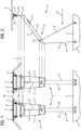
- pantograph 2 for an electrically or hybrid-electrically driven road vehicle 1, for example a heavy commercial vehicle or a bus, which is designed and provided for feeding in traction energy from a two-pole catenary system having a contact wire 3 for each contact pole.
- the pantograph 2 comprises an erectable support linkage 4, which is supported in an articulated manner on a linkage base 5 on the vehicle side and carries a rocker arrangement on the contact wire side.
- the rocker arrangement has a rocker frame 6 for each contact pole.
- Each rocker frame 6 is articulated and rotatable about a vehicle transverse axis 7 connected to the support linkage 4 .
- the support linkage 4 has a support arm 9 that can be erected for each contact pole.
- Each support arm 9 has a lower arm 10 that is supported on the linkage base, an upper arm 11 that is articulated to the lower arm 10 and that supports the respective rocker frame 6.
- a coupling rod 12 is articulated to the upper arm 11 and linkage base 5 in such a way that when a support arm 9 whose upper arm 11 is stretched relative to the lower arm 10.
- Each guide rod 13 is articulated to the lower arm 10 and rocker frame 6 in such a way that when the support arm 9 is erected, the rocker frame 6 is guided in such a way that a contact strip 8 mounted on the rocker frame 6 remains facing the contact wire 3 .
- the guide rods 13 each have a linear joint 14 for changing the length ⁇ L of the guide rod 13 .
- the linear joints 14 can be designed, for example, as a spring element or as a spring damper in the guide rods 13 .
- the linear joints 14 allow a change in length ⁇ L of the guide rod 13 compared to the respective upper arm 11 of the support arms 9, as a result of which a corrective rotation of the rocker frame 6 about the respective transverse axis 7 of the vehicle is possible.
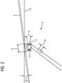
- the corrective rotation allows the ground contact surface of the contact strip 8 carried by the rocker frame 6 to adapt to changes in an incline ⁇ or an incline ⁇ of the contact wire 3 relative to the roadway surface 15 .
- a width B of the contact strips 8 measured in the longitudinal direction 16 of the vehicle is at least 6 cm.
- the enlarged contact surface forms a tilting protection of the rocker frame 6, which in turn improves the contact quality of the pantograph 2.
- the width B of the contact strip can be selected to be larger, the higher the current intensity to be transmitted, the maximum driving speed of the road vehicle 1 and the magnitude of the gradient ⁇ or gradient ⁇ of the contact wire 3 relative to the road surface 15 that is to be expected.
- the contact strips 8 are each mounted resiliently on the rocker frame 6 in such a way that a tilting movement ⁇ of the contact strip 8 relative to the rocker frame 6 about a vehicle transverse axis is made possible.
- the spring-elastic mounting enables an additional degree of tilting freedom of the contact strips 8 relative to the rocker frame 6.
- the mounting can be formed, for example, by a series of tilting springs 17 arranged in pairs in the direction of travel 16 one behind the other. The elastic restoring forces of the tilting springs 17 automatically bring the contact strips 8 back into their non-tilted starting positions when external forces are reduced.
- an effective compensation mechanism is provided here, which balances the contact strips 8 tends to compensate for gradients ⁇ and gradients ⁇ of the contact wires 3 relative to the roadway surface 15 or the rod base 5.
- the quality of contact is improved by the achieved uniform sliding contact with a constant contact area between sliding strips 8 and contact wires 3 .
- the rocker frames 6 are connected by a bridge member 18 in such a way that a contact wire 3 is prevented from dipping between the contact strips 8 .
- the pontic 18 is in FIG 1 shown as a dashed line and can be articulated, for example, on the rocker frames 6. It is arranged and shaped in such a way that a contact wire 3 is prevented from slipping into the space between the adjacent rocker frames 6 .
- the bridge member 18 can be designed as an electrically insulating bracket.
- the bridge member 18 is connected to the rocker frames 6 via compensating joints 19 which allow a relative movement between the rocker frames 6 .
- the articulated connection with the rocker frames 6 allows compensation for different longitudinal positions and height differences between the rocker frames 6.
- the compensating joints 19 interact with stop elements which limit the relative movement between the rocker frames 6. By the stop elements interacting directly with the compensating joints 19 of the bridge member 18, an adjustability for limiting the height difference of the rocker frames 6 is given at the point of origin.
- the support linkage is coupled to a lifting drive, which is known per se and is therefore not shown, for raising the support arms 9 together, which can be designed as air bellows.
Landscapes
- Engineering & Computer Science (AREA)
- Power Engineering (AREA)
- Transportation (AREA)
- Mechanical Engineering (AREA)
- Current-Collector Devices For Electrically Propelled Vehicles (AREA)
Applications Claiming Priority (1)
| Application Number | Priority Date | Filing Date | Title |
|---|---|---|---|
| DE102020211775.6A DE102020211775A1 (de) | 2020-09-21 | 2020-09-21 | Stromabnehmer und ein mit einem solchen ausgestattetes, elektrisch oder hybridelektrisch angetriebenes Straßenfahrzeug |
Publications (1)
| Publication Number | Publication Date |
|---|---|
| EP3971013A1 true EP3971013A1 (fr) | 2022-03-23 |
Family
ID=77738970
Family Applications (1)
| Application Number | Title | Priority Date | Filing Date |
|---|---|---|---|
| EP21196228.7A Pending EP3971013A1 (fr) | 2020-09-21 | 2021-09-13 | Collecteur de courant et véhicule routier à moteur électrique ou hybride électrique équipé d'un tel collecteur de courant |
Country Status (2)
| Country | Link |
|---|---|
| EP (1) | EP3971013A1 (fr) |
| DE (1) | DE102020211775A1 (fr) |
Cited By (2)
| Publication number | Priority date | Publication date | Assignee | Title |
|---|---|---|---|---|
| WO2023213478A1 (fr) * | 2022-05-03 | 2023-11-09 | Siemens Mobility GmbH | Véhicule non ferroviaire ayant un collecteur de courant |
| WO2025051409A1 (fr) * | 2023-09-06 | 2025-03-13 | Siemens Mobility GmbH | Collecteur de courant pour véhicule électrique ou hybride-électrique et véhicule équipé d'un tel collecteur de courant |
Families Citing this family (2)
| Publication number | Priority date | Publication date | Assignee | Title |
|---|---|---|---|---|
| DE102022210217A1 (de) * | 2022-09-27 | 2024-03-28 | Siemens Mobility GmbH | Stromabnehmer |
| DE102023205573A1 (de) | 2023-06-15 | 2024-12-19 | Siemens Mobility GmbH | Stromabnehmer für ein elektrisch oder hybridelektrisch angetriebenes Fahrzeug und ein mit einem solchen ausgestattetes Fahrzeug |
Citations (4)
| Publication number | Priority date | Publication date | Assignee | Title |
|---|---|---|---|---|
| FR78582E (fr) * | 1960-10-19 | 1962-08-10 | Karl Wanisch | Balai muni d'un dispositif d'amortissement pour motrices électriques |
| DE3536843A1 (de) * | 1985-10-16 | 1987-04-16 | Dornier System Gmbh | Stromabnehmervorrichtung |
| DE102011076620A1 (de) * | 2011-05-27 | 2012-11-29 | Siemens Aktiengesellschaft | Nicht schienengebundenes Fahrzeug |
| DE102017203046A1 (de) | 2017-02-24 | 2018-08-30 | Siemens Aktiengesellschaft | Stromabnehmer für mehrpoliges Fahrleitungssystem |
Family Cites Families (4)
| Publication number | Priority date | Publication date | Assignee | Title |
|---|---|---|---|---|
| AT357606B (de) | 1977-07-12 | 1980-07-25 | Siemens Ag Oesterreich | Vertikalgefuehrter hochgeschwindigkeits-strom- abnehmer |
| JP2004304895A (ja) | 2003-03-31 | 2004-10-28 | Railway Technical Res Inst | パンタグラフ |
| JP5582571B2 (ja) | 2010-09-30 | 2014-09-03 | 東日本旅客鉄道株式会社 | すり板組立体の組立治具 |
| CN104999915B (zh) | 2015-07-16 | 2017-12-12 | 金华青年汽车制造有限公司 | 一种客车用受电弓装置 |
-
2020
- 2020-09-21 DE DE102020211775.6A patent/DE102020211775A1/de not_active Withdrawn
-
2021
- 2021-09-13 EP EP21196228.7A patent/EP3971013A1/fr active Pending
Patent Citations (4)
| Publication number | Priority date | Publication date | Assignee | Title |
|---|---|---|---|---|
| FR78582E (fr) * | 1960-10-19 | 1962-08-10 | Karl Wanisch | Balai muni d'un dispositif d'amortissement pour motrices électriques |
| DE3536843A1 (de) * | 1985-10-16 | 1987-04-16 | Dornier System Gmbh | Stromabnehmervorrichtung |
| DE102011076620A1 (de) * | 2011-05-27 | 2012-11-29 | Siemens Aktiengesellschaft | Nicht schienengebundenes Fahrzeug |
| DE102017203046A1 (de) | 2017-02-24 | 2018-08-30 | Siemens Aktiengesellschaft | Stromabnehmer für mehrpoliges Fahrleitungssystem |
Cited By (2)
| Publication number | Priority date | Publication date | Assignee | Title |
|---|---|---|---|---|
| WO2023213478A1 (fr) * | 2022-05-03 | 2023-11-09 | Siemens Mobility GmbH | Véhicule non ferroviaire ayant un collecteur de courant |
| WO2025051409A1 (fr) * | 2023-09-06 | 2025-03-13 | Siemens Mobility GmbH | Collecteur de courant pour véhicule électrique ou hybride-électrique et véhicule équipé d'un tel collecteur de courant |
Also Published As
| Publication number | Publication date |
|---|---|
| DE102020211775A1 (de) | 2022-03-24 |
Similar Documents
| Publication | Publication Date | Title |
|---|---|---|
| EP3971013A1 (fr) | Collecteur de courant et véhicule routier à moteur électrique ou hybride électrique équipé d'un tel collecteur de courant | |
| EP4313662A1 (fr) | Collecteur de courant pour véhicule routier électrique ou hybride | |
| DE102014014200B4 (de) | Andrahtungsvorrichtung und zugehöriger Rutenstromabnehmer für doppelpolige Fahrdrahtsysteme | |
| DE102012223068A1 (de) | Nicht schienengebundenes Fahrzeug | |
| DE102021208028B4 (de) | Stromabnehmer und ein mit einem solchen ausgestattetes Straßenfahrzeug | |
| EP3999373A1 (fr) | Véhicule non guidé doté d'un pantographe | |
| WO2021058221A1 (fr) | Station de charge pour accumulateur d'énergie embarqué | |
| WO2023227325A1 (fr) | Collecteur de courant et véhicule routier équipé dudit collecteur | |
| WO2021037351A1 (fr) | Unité de positionnement et procédé de mise en contact | |
| DE102009056589A1 (de) | Stromschuhhalterung für O-Bus- und Dritte-Schiene-Stromabnehmer | |
| DE102020207211A1 (de) | Nicht spurgebundenes Fahrzeug mit einem Stromabnehmer | |
| EP1326760B1 (fr) | Suspension d'archet | |
| EP0844131B1 (fr) | Pantographe pour prise de courant de véhicules à propulsion électrique avec alimentation par ligne aérienne | |
| DE3632758A1 (de) | Oberleitungsstuetzpunkt insbesondere zur anbringung in eingleisigen tunneln | |
| CH706674B1 (de) | Stromabnehmerrute für fahrdrahtgespeiste Fahrzeuge. | |
| DE102022204337A1 (de) | Nicht spurgebundenes Fahrzeug mit einem Stromabnehmer | |
| EP3339131B1 (fr) | Train doté d'au moins un dispositif de suspension | |
| WO2025067745A1 (fr) | Collecteur de courant et véhicule routier équipé d'un tel collecteur de courant | |
| DE2121613C3 (fr) | ||
| DE102023205573A1 (de) | Stromabnehmer für ein elektrisch oder hybridelektrisch angetriebenes Fahrzeug und ein mit einem solchen ausgestattetes Fahrzeug | |
| DE19731981C1 (de) | Oberleitungsanlage | |
| EP0936100B1 (fr) | Capteur de courant monté sur le toit de véhicules ferroviaires avec système d'inclinaison | |
| EP4705135A1 (fr) | Collecteur de courant pour véhicule électrique ou hybride-électrique et véhicule équipé d'un tel collecteur de courant | |
| DE102023201320A1 (de) | Stromabnehmer für ein elektrisch oder hybridelektrisch angetriebenes Straßenfahrzeug | |
| DE383546C (de) | Einrichtung zur Stromabnahme bei elektrischen Bahnen mit mehreren Stromabnehmern |
Legal Events
| Date | Code | Title | Description |
|---|---|---|---|
| PUAI | Public reference made under article 153(3) epc to a published international application that has entered the european phase |
Free format text: ORIGINAL CODE: 0009012 |
|
| STAA | Information on the status of an ep patent application or granted ep patent |
Free format text: STATUS: THE APPLICATION HAS BEEN PUBLISHED |
|
| AK | Designated contracting states |
Kind code of ref document: A1 Designated state(s): AL AT BE BG CH CY CZ DE DK EE ES FI FR GB GR HR HU IE IS IT LI LT LU LV MC MK MT NL NO PL PT RO RS SE SI SK SM TR |
|
| STAA | Information on the status of an ep patent application or granted ep patent |
Free format text: STATUS: REQUEST FOR EXAMINATION WAS MADE |
|
| 17P | Request for examination filed |
Effective date: 20220819 |
|
| RBV | Designated contracting states (corrected) |
Designated state(s): AL AT BE BG CH CY CZ DE DK EE ES FI FR GB GR HR HU IE IS IT LI LT LU LV MC MK MT NL NO PL PT RO RS SE SI SK SM TR |
|
| RAP3 | Party data changed (applicant data changed or rights of an application transferred) |
Owner name: SIEMENS MOBILITY GMBH |