EP3971018A1 - Circuit et système de charge-décharge, et véhicule électrique - Google Patents
Circuit et système de charge-décharge, et véhicule électrique Download PDFInfo
- Publication number
- EP3971018A1 EP3971018A1 EP20862783.6A EP20862783A EP3971018A1 EP 3971018 A1 EP3971018 A1 EP 3971018A1 EP 20862783 A EP20862783 A EP 20862783A EP 3971018 A1 EP3971018 A1 EP 3971018A1
- Authority
- EP
- European Patent Office
- Prior art keywords
- terminal
- switch
- bridge arm
- charging
- inductor
- Prior art date
- Legal status (The legal status is an assumption and is not a legal conclusion. Google has not performed a legal analysis and makes no representation as to the accuracy of the status listed.)
- Pending
Links
Images






Classifications
-
- B—PERFORMING OPERATIONS; TRANSPORTING
- B60—VEHICLES IN GENERAL
- B60L—PROPULSION OF ELECTRICALLY-PROPELLED VEHICLES; SUPPLYING ELECTRIC POWER FOR AUXILIARY EQUIPMENT OF ELECTRICALLY-PROPELLED VEHICLES; ELECTRODYNAMIC BRAKE SYSTEMS FOR VEHICLES IN GENERAL; MAGNETIC SUSPENSION OR LEVITATION FOR VEHICLES; MONITORING OPERATING VARIABLES OF ELECTRICALLY-PROPELLED VEHICLES; ELECTRIC SAFETY DEVICES FOR ELECTRICALLY-PROPELLED VEHICLES
- B60L53/00—Methods of charging batteries, specially adapted for electric vehicles; Charging stations or on-board charging equipment therefor; Exchange of energy storage elements in electric vehicles
- B60L53/20—Methods of charging batteries, specially adapted for electric vehicles; Charging stations or on-board charging equipment therefor; Exchange of energy storage elements in electric vehicles characterised by converters located in the vehicle
- B60L53/24—Using the vehicle's propulsion converter for charging
-
- B—PERFORMING OPERATIONS; TRANSPORTING
- B60—VEHICLES IN GENERAL
- B60L—PROPULSION OF ELECTRICALLY-PROPELLED VEHICLES; SUPPLYING ELECTRIC POWER FOR AUXILIARY EQUIPMENT OF ELECTRICALLY-PROPELLED VEHICLES; ELECTRODYNAMIC BRAKE SYSTEMS FOR VEHICLES IN GENERAL; MAGNETIC SUSPENSION OR LEVITATION FOR VEHICLES; MONITORING OPERATING VARIABLES OF ELECTRICALLY-PROPELLED VEHICLES; ELECTRIC SAFETY DEVICES FOR ELECTRICALLY-PROPELLED VEHICLES
- B60L53/00—Methods of charging batteries, specially adapted for electric vehicles; Charging stations or on-board charging equipment therefor; Exchange of energy storage elements in electric vehicles
-
- B—PERFORMING OPERATIONS; TRANSPORTING
- B60—VEHICLES IN GENERAL
- B60L—PROPULSION OF ELECTRICALLY-PROPELLED VEHICLES; SUPPLYING ELECTRIC POWER FOR AUXILIARY EQUIPMENT OF ELECTRICALLY-PROPELLED VEHICLES; ELECTRODYNAMIC BRAKE SYSTEMS FOR VEHICLES IN GENERAL; MAGNETIC SUSPENSION OR LEVITATION FOR VEHICLES; MONITORING OPERATING VARIABLES OF ELECTRICALLY-PROPELLED VEHICLES; ELECTRIC SAFETY DEVICES FOR ELECTRICALLY-PROPELLED VEHICLES
- B60L53/00—Methods of charging batteries, specially adapted for electric vehicles; Charging stations or on-board charging equipment therefor; Exchange of energy storage elements in electric vehicles
- B60L53/20—Methods of charging batteries, specially adapted for electric vehicles; Charging stations or on-board charging equipment therefor; Exchange of energy storage elements in electric vehicles characterised by converters located in the vehicle
-
- H—ELECTRICITY
- H01—ELECTRIC ELEMENTS
- H01M—PROCESSES OR MEANS, e.g. BATTERIES, FOR THE DIRECT CONVERSION OF CHEMICAL ENERGY INTO ELECTRICAL ENERGY
- H01M10/00—Secondary cells; Manufacture thereof
- H01M10/42—Methods or arrangements for servicing or maintenance of secondary cells or secondary half-cells
- H01M10/44—Methods for charging or discharging
-
- H—ELECTRICITY
- H02—GENERATION; CONVERSION OR DISTRIBUTION OF ELECTRIC POWER
- H02M—APPARATUS FOR CONVERSION BETWEEN AC AND AC, BETWEEN AC AND DC, OR BETWEEN DC AND DC, AND FOR USE WITH MAINS OR SIMILAR POWER SUPPLY SYSTEMS; CONVERSION OF DC OR AC INPUT POWER INTO SURGE OUTPUT POWER; CONTROL OR REGULATION THEREOF
- H02M1/00—Details of apparatus for conversion
- H02M1/10—Arrangements incorporating converting means for enabling loads to be operated at will from different kinds of power supplies, e.g. from AC or DC
-
- H—ELECTRICITY
- H02—GENERATION; CONVERSION OR DISTRIBUTION OF ELECTRIC POWER
- H02M—APPARATUS FOR CONVERSION BETWEEN AC AND AC, BETWEEN AC AND DC, OR BETWEEN DC AND DC, AND FOR USE WITH MAINS OR SIMILAR POWER SUPPLY SYSTEMS; CONVERSION OF DC OR AC INPUT POWER INTO SURGE OUTPUT POWER; CONTROL OR REGULATION THEREOF
- H02M3/00—Conversion of DC power input into DC power output
- H02M3/02—Conversion of DC power input into DC power output without intermediate conversion into AC
- H02M3/04—Conversion of DC power input into DC power output without intermediate conversion into AC by static converters
- H02M3/10—Conversion of DC power input into DC power output without intermediate conversion into AC by static converters using discharge tubes with control electrode or semiconductor devices with control electrode
- H02M3/145—Conversion of DC power input into DC power output without intermediate conversion into AC by static converters using discharge tubes with control electrode or semiconductor devices with control electrode using devices of a triode or transistor type requiring continuous application of a control signal
- H02M3/155—Conversion of DC power input into DC power output without intermediate conversion into AC by static converters using discharge tubes with control electrode or semiconductor devices with control electrode using devices of a triode or transistor type requiring continuous application of a control signal using semiconductor devices only
- H02M3/156—Conversion of DC power input into DC power output without intermediate conversion into AC by static converters using discharge tubes with control electrode or semiconductor devices with control electrode using devices of a triode or transistor type requiring continuous application of a control signal using semiconductor devices only with automatic control of output voltage or current, e.g. switching regulators
- H02M3/158—Conversion of DC power input into DC power output without intermediate conversion into AC by static converters using discharge tubes with control electrode or semiconductor devices with control electrode using devices of a triode or transistor type requiring continuous application of a control signal using semiconductor devices only with automatic control of output voltage or current, e.g. switching regulators including plural semiconductor devices as final control devices for a single load
-
- H—ELECTRICITY
- H02—GENERATION; CONVERSION OR DISTRIBUTION OF ELECTRIC POWER
- H02M—APPARATUS FOR CONVERSION BETWEEN AC AND AC, BETWEEN AC AND DC, OR BETWEEN DC AND DC, AND FOR USE WITH MAINS OR SIMILAR POWER SUPPLY SYSTEMS; CONVERSION OF DC OR AC INPUT POWER INTO SURGE OUTPUT POWER; CONTROL OR REGULATION THEREOF
- H02M7/00—Conversion of AC power input into DC power output; Conversion of DC power input into AC power output
- H02M7/42—Conversion of DC power input into AC power output without possibility of reversal
- H02M7/44—Conversion of DC power input into AC power output without possibility of reversal by static converters
- H02M7/48—Conversion of DC power input into AC power output without possibility of reversal by static converters using discharge tubes with control electrode or semiconductor devices with control electrode
- H02M7/53—Conversion of DC power input into AC power output without possibility of reversal by static converters using discharge tubes with control electrode or semiconductor devices with control electrode using devices of a triode or transistor type requiring continuous application of a control signal
- H02M7/537—Conversion of DC power input into AC power output without possibility of reversal by static converters using discharge tubes with control electrode or semiconductor devices with control electrode using devices of a triode or transistor type requiring continuous application of a control signal using semiconductor devices only, e.g. single switched pulse inverters
- H02M7/5387—Conversion of DC power input into AC power output without possibility of reversal by static converters using discharge tubes with control electrode or semiconductor devices with control electrode using devices of a triode or transistor type requiring continuous application of a control signal using semiconductor devices only, e.g. single switched pulse inverters in a bridge configuration
-
- H—ELECTRICITY
- H01—ELECTRIC ELEMENTS
- H01M—PROCESSES OR MEANS, e.g. BATTERIES, FOR THE DIRECT CONVERSION OF CHEMICAL ENERGY INTO ELECTRICAL ENERGY
- H01M2220/00—Batteries for particular applications
- H01M2220/20—Batteries in motive systems, e.g. vehicle, ship, plane
-
- H—ELECTRICITY
- H02—GENERATION; CONVERSION OR DISTRIBUTION OF ELECTRIC POWER
- H02M—APPARATUS FOR CONVERSION BETWEEN AC AND AC, BETWEEN AC AND DC, OR BETWEEN DC AND DC, AND FOR USE WITH MAINS OR SIMILAR POWER SUPPLY SYSTEMS; CONVERSION OF DC OR AC INPUT POWER INTO SURGE OUTPUT POWER; CONTROL OR REGULATION THEREOF
- H02M1/00—Details of apparatus for conversion
- H02M1/0067—Converter structures employing plural converter units, other than for parallel operation of the units on a single load
- H02M1/007—Plural converter units in cascade
-
- H—ELECTRICITY
- H02—GENERATION; CONVERSION OR DISTRIBUTION OF ELECTRIC POWER
- H02M—APPARATUS FOR CONVERSION BETWEEN AC AND AC, BETWEEN AC AND DC, OR BETWEEN DC AND DC, AND FOR USE WITH MAINS OR SIMILAR POWER SUPPLY SYSTEMS; CONVERSION OF DC OR AC INPUT POWER INTO SURGE OUTPUT POWER; CONTROL OR REGULATION THEREOF
- H02M1/00—Details of apparatus for conversion
- H02M1/0095—Hybrid converter topologies, e.g. NPC mixed with flying capacitor, thyristor converter mixed with MMC or charge pump mixed with buck
-
- H—ELECTRICITY
- H02—GENERATION; CONVERSION OR DISTRIBUTION OF ELECTRIC POWER
- H02M—APPARATUS FOR CONVERSION BETWEEN AC AND AC, BETWEEN AC AND DC, OR BETWEEN DC AND DC, AND FOR USE WITH MAINS OR SIMILAR POWER SUPPLY SYSTEMS; CONVERSION OF DC OR AC INPUT POWER INTO SURGE OUTPUT POWER; CONTROL OR REGULATION THEREOF
- H02M1/00—Details of apparatus for conversion
- H02M1/44—Circuits or arrangements for compensating for electromagnetic interference in converters or inverters
-
- H—ELECTRICITY
- H02—GENERATION; CONVERSION OR DISTRIBUTION OF ELECTRIC POWER
- H02M—APPARATUS FOR CONVERSION BETWEEN AC AND AC, BETWEEN AC AND DC, OR BETWEEN DC AND DC, AND FOR USE WITH MAINS OR SIMILAR POWER SUPPLY SYSTEMS; CONVERSION OF DC OR AC INPUT POWER INTO SURGE OUTPUT POWER; CONTROL OR REGULATION THEREOF
- H02M3/00—Conversion of DC power input into DC power output
- H02M3/02—Conversion of DC power input into DC power output without intermediate conversion into AC
- H02M3/04—Conversion of DC power input into DC power output without intermediate conversion into AC by static converters
- H02M3/10—Conversion of DC power input into DC power output without intermediate conversion into AC by static converters using discharge tubes with control electrode or semiconductor devices with control electrode
- H02M3/145—Conversion of DC power input into DC power output without intermediate conversion into AC by static converters using discharge tubes with control electrode or semiconductor devices with control electrode using devices of a triode or transistor type requiring continuous application of a control signal
- H02M3/155—Conversion of DC power input into DC power output without intermediate conversion into AC by static converters using discharge tubes with control electrode or semiconductor devices with control electrode using devices of a triode or transistor type requiring continuous application of a control signal using semiconductor devices only
- H02M3/1552—Boost converters exploiting the leakage inductance of a transformer or of an alternator as boost inductor
-
- H—ELECTRICITY
- H02—GENERATION; CONVERSION OR DISTRIBUTION OF ELECTRIC POWER
- H02M—APPARATUS FOR CONVERSION BETWEEN AC AND AC, BETWEEN AC AND DC, OR BETWEEN DC AND DC, AND FOR USE WITH MAINS OR SIMILAR POWER SUPPLY SYSTEMS; CONVERSION OF DC OR AC INPUT POWER INTO SURGE OUTPUT POWER; CONTROL OR REGULATION THEREOF
- H02M7/00—Conversion of AC power input into DC power output; Conversion of DC power input into AC power output
- H02M7/02—Conversion of AC power input into DC power output without possibility of reversal
- H02M7/04—Conversion of AC power input into DC power output without possibility of reversal by static converters
- H02M7/06—Conversion of AC power input into DC power output without possibility of reversal by static converters using discharge tubes without control electrode or semiconductor devices without control electrode
-
- H—ELECTRICITY
- H02—GENERATION; CONVERSION OR DISTRIBUTION OF ELECTRIC POWER
- H02M—APPARATUS FOR CONVERSION BETWEEN AC AND AC, BETWEEN AC AND DC, OR BETWEEN DC AND DC, AND FOR USE WITH MAINS OR SIMILAR POWER SUPPLY SYSTEMS; CONVERSION OF DC OR AC INPUT POWER INTO SURGE OUTPUT POWER; CONTROL OR REGULATION THEREOF
- H02M7/00—Conversion of AC power input into DC power output; Conversion of DC power input into AC power output
- H02M7/02—Conversion of AC power input into DC power output without possibility of reversal
- H02M7/04—Conversion of AC power input into DC power output without possibility of reversal by static converters
- H02M7/12—Conversion of AC power input into DC power output without possibility of reversal by static converters using discharge tubes with control electrode or semiconductor devices with control electrode
- H02M7/21—Conversion of AC power input into DC power output without possibility of reversal by static converters using discharge tubes with control electrode or semiconductor devices with control electrode using devices of a triode or transistor type requiring continuous application of a control signal
- H02M7/217—Conversion of AC power input into DC power output without possibility of reversal by static converters using discharge tubes with control electrode or semiconductor devices with control electrode using devices of a triode or transistor type requiring continuous application of a control signal using semiconductor devices only
- H02M7/219—Conversion of AC power input into DC power output without possibility of reversal by static converters using discharge tubes with control electrode or semiconductor devices with control electrode using devices of a triode or transistor type requiring continuous application of a control signal using semiconductor devices only in a bridge configuration
-
- H—ELECTRICITY
- H02—GENERATION; CONVERSION OR DISTRIBUTION OF ELECTRIC POWER
- H02M—APPARATUS FOR CONVERSION BETWEEN AC AND AC, BETWEEN AC AND DC, OR BETWEEN DC AND DC, AND FOR USE WITH MAINS OR SIMILAR POWER SUPPLY SYSTEMS; CONVERSION OF DC OR AC INPUT POWER INTO SURGE OUTPUT POWER; CONTROL OR REGULATION THEREOF
- H02M7/00—Conversion of AC power input into DC power output; Conversion of DC power input into AC power output
- H02M7/66—Conversion of AC power input into DC power output; Conversion of DC power input into AC power output with possibility of reversal
- H02M7/68—Conversion of AC power input into DC power output; Conversion of DC power input into AC power output with possibility of reversal by static converters
- H02M7/72—Conversion of AC power input into DC power output; Conversion of DC power input into AC power output with possibility of reversal by static converters using discharge tubes with control electrode or semiconductor devices with control electrode
- H02M7/79—Conversion of AC power input into DC power output; Conversion of DC power input into AC power output with possibility of reversal by static converters using discharge tubes with control electrode or semiconductor devices with control electrode using devices of a triode or transistor type requiring continuous application of a control signal
- H02M7/797—Conversion of AC power input into DC power output; Conversion of DC power input into AC power output with possibility of reversal by static converters using discharge tubes with control electrode or semiconductor devices with control electrode using devices of a triode or transistor type requiring continuous application of a control signal using semiconductor devices only
Definitions
- Embodiments of this application relate to the field of electric vehicles, and more specifically, to a charging and discharging circuit and system, and an electric vehicle.
- FIG. 1 is a schematic diagram of a charging and discharging system 100 of an existing electric vehicle.
- the charging and discharging system 100 of the existing electric vehicle includes an on-board charger 101, a motor control unit 102, a motor 103, and a battery 104.
- the on-board charger 101, the motor control unit 102, the motor 103, and the battery 104 are mutually independent components.
- the charging and discharging system 100 of the electric vehicle has a charging function and a driving function.
- the charging function means that when the electric vehicle is in a non-running state, the on-board charger 101 converts a received alternating current into a direct current, performs step-down processing on the direct current, and transmits a direct current obtained after the step-down to the battery 104, to enable the battery 104 to be in a charging state.
- the driving function means that when the electric vehicle is in a non-charging state, the motor control unit 102 converts a direct current provided by the battery 104 into an alternating current, and transmits the alternating current to the motor 103, to enable the motor 103 to run.
- the charging and discharging system of the existing electric vehicle has a relatively large quantity of components and occupies large space, and therefore cannot meet a miniaturization requirement. Therefore, how to reduce a quantity of components in a charging and discharging system of an electric vehicle to reduce a volume of the charging and discharging system becomes a technical problem that needs to be resolved urgently at present.
- Embodiments of this application provide a charging and discharging circuit and system, and an electric vehicle, to reduce a quantity of components and reduce a volume.
- an embodiment of this application provides a charging and discharging circuit.
- the charging and discharging circuit includes a battery, a motor, a first charging interface, a first bridge arm, a second bridge arm, a third bridge arm, a first switch, a second switch, a third switch, a fourth switch, a fifth switch, a sixth switch, a seventh switch, and an eighth switch.
- a positive output terminal of the battery is separately connected to a positive terminal of the first bridge arm, a positive terminal of the second bridge arm, and a positive terminal of the third bridge arm by using the first switch, and a negative output terminal of the battery is separately connected to a negative terminal of the first bridge arm, a negative terminal of the second bridge arm, and a negative terminal of the third bridge arm.
- the motor includes a first inductor, a second inductor, and a third inductor, a first terminal of the first inductor is connected to a middle point of the first bridge arm, a first terminal of the second inductor is connected to a middle point of the second bridge arm, a first terminal of the third inductor is connected to a middle point of the third bridge arm, and a second terminal of the first inductor, a second terminal of the second inductor, and a second terminal of the third inductor are connected to a first terminal of the fourth switch.
- a first output terminal of the first charging interface is connected to the second terminal of the second inductor, and a second output terminal of the first charging interface is connected to the middle point of the third bridge arm.
- the second switch is disposed between the middle point of the second bridge arm and the first terminal of the second inductor
- the third switch is disposed between the middle point of the third bridge arm and the first terminal of the third inductor
- the fifth switch is disposed between the positive output terminal of the battery and the first terminal of the third inductor
- the sixth switch is disposed between the middle point of the second bridge arm and the second terminal of the third inductor
- the seventh switch is disposed between the first output terminal of the first charging interface and the second terminal of the second inductor
- the eighth switch is disposed between the first terminal of the second inductor and the second terminal of the first inductor.
- the first switch, the second switch, the third switch, and the fourth switch are all in a closed state
- the fifth switch, the sixth switch, the seventh switch, and the eighth switch are all in an open state
- the first bridge arm, the second bridge arm, and the third bridge arm constitute a direct current-alternating current converter
- the first inductor, the second inductor, and the third inductor constitute the motor.
- the battery provides a direct current for the direct current-alternating current converter
- the direct current-alternating current converter converts the direct current provided by the battery into an alternating current and sends the alternating current to the motor.
- the motor When the motor receives the alternating current sent by the direct current-alternating current converter, the motor starts to run.
- the charging and discharging circuit When the charging and discharging circuit is in a charging mode, the first switch, the second switch, the third switch, and the fourth switch are all in an open state, the fifth switch, the sixth switch, the seventh switch, and the eighth switch are all in a closed state, the first bridge arm, the third bridge arm, the first inductor, and the second inductor constitute an alternating current-direct current converter, and the second bridge arm and the third inductor constitute a step-down circuit.
- the first charging interface receives an alternating current provided by an external device, and sends the alternating current to the alternating current-direct current converter.
- the alternating current-direct current converter converts the alternating current provided by the first charging interface into a direct current, and sends the high-voltage direct current to the step-down circuit.
- the step-down circuit performs step-down processing on the high-voltage direct current provided by the alternating current-direct current converter, to obtain a low-voltage direct current, and sends the low-voltage direct current to the battery, to charge the battery. Therefore, the first switch, the second switch, the third switch, the fourth switch, the fifth switch, the sixth switch, the seventh switch, and the eighth switch are controlled, so that the charging and discharging circuit implements the driving mode and the charging mode. Therefore, an unnecessary component in the charging and discharging circuit is omitted, thereby reducing a volume of the charging and discharging circuit.
- the charging and discharging circuit further includes a first capacitor and a second capacitor.
- a positive terminal of the first capacitor is connected to the positive output terminal of the battery, and a negative terminal of the first capacitor is connected to the negative output terminal of the battery.
- a positive terminal of the second capacitor is connected to a first terminal of the first switch, a negative terminal of the second capacitor is connected to the negative output terminal of the battery, and a second terminal of the first switch is connected to the positive output terminal of the battery.
- the first capacitor and the second capacitor are configured to filter input of the direct current-alternating current converter.
- the first capacitor is configured to filter output of the step-down circuit
- the second capacitor is configured to filter output of the alternating current-direct current converter.
- the charging and discharging circuit further includes a filtering module.
- a first input terminal of the filtering module is connected to the first output terminal of the first charging interface, and a second input terminal of the filtering module is connected to the second output terminal of the first charging interface.
- a first output terminal of the filtering module is connected to the second terminal of the second inductor by using the seventh switch, and a second output terminal of the filtering module is connected to the middle point of the third bridge arm.
- the filtering module is configured to suppress high-frequency interference in the charging and discharging circuit.
- the charging and discharging circuit further includes a second charging interface and a three-phase rectifier bridge arm.
- a first input terminal of the three-phase rectifier bridge arm is connected to a first output terminal of the second charging interface
- a second input terminal of the three-phase rectifier bridge arm is connected to a second output terminal of the second charging interface
- a third input terminal of the three-phase rectifier bridge arm is connected to a third output terminal of the second charging interface.
- a first output terminal of the three-phase rectifier bridge arm is connected to the first input terminal of the filtering module
- a second output terminal of the three-phase rectifier bridge arm is connected to the second input terminal of the filtering module.
- the second charging interface is configured to receive a three-phase alternating current provided by an external device, and the three-phase rectifier bridge arm is configured to convert the three-phase alternating current sent by the second charging interface into a two-phase alternating current.
- the three-phase rectifier bridge arm includes a first diode, a second diode, a third diode, a fourth diode, a fifth diode, and a sixth diode.
- a negative electrode of the first diode, a negative electrode of the third diode, and a negative electrode of the fifth diode are all connected to the first input terminal of the filtering module, and a positive electrode of the second diode, a positive electrode of the fourth diode, and a positive electrode of the sixth diode are all connected to the second input terminal of the filtering module.
- a positive electrode of the first diode and a negative electrode of the second diode are both connected to the first output terminal of the second charging interface, a positive electrode of the third diode and a negative electrode of the fourth diode are both connected to the second output terminal of the second charging interface, and a positive electrode of the fifth diode and a negative electrode of the sixth diode are both connected to the third output terminal of the second charging interface.
- the first bridge arm includes a first switching transistor and a second switching transistor
- the second bridge arm includes a third switching transistor and a fourth switching transistor
- the third bridge arm includes a fifth switching transistor and a sixth switching transistor.
- a second pin of the first switching transistor is connected to a first pin of the second switching transistor
- a second pin of the third switching transistor is connected to a first pin of the fourth switching transistor
- a second pin of the fifth switching transistor is connected to a first pin of the sixth switching transistor.
- a first pin of the first switching transistor, a first pin of the third switching transistor, and a first pin of the fifth switching transistor are all connected to the positive output terminal of the battery by using the first switch, and a second pin of the second switching transistor, a second pin of the fourth switching transistor, and a second pin of the sixth switching transistor are all connected to the negative output terminal of the battery.
- the second pin of the first switching transistor and the first pin of the second switching transistor are both connected to the first terminal of the first inductor
- the second pin of the third switching transistor and the first pin of the fourth switching transistor are both connected to the first terminal of the second inductor
- the second pin of the fifth switching transistor and the first pin of the sixth switching transistor are both connected to the first terminal of the third inductor.
- an embodiment of this application provides a charging and discharging system.
- the charging and discharging system includes a charging and discharging circuit and a controller, and the charging and discharging circuit includes a battery, a motor, a first charging interface, a first bridge arm, a second bridge arm, a third bridge arm, a first switch, a second switch, a third switch, a fourth switch, a fifth switch, a sixth switch, a seventh switch, and an eighth switch.
- the controller is separately connected to a control terminal of the first switch, a control terminal of the second switch, a control terminal of the third switch, a control terminal of the fourth switch, a control terminal of the fifth switch, a control terminal of the sixth switch, a control terminal of the seventh switch, and a control terminal of the eighth switch.
- a positive output terminal of the battery is separately connected to a positive terminal of the first bridge arm, a positive terminal of the second bridge arm, and a positive terminal of the third bridge arm by using the first switch, and a negative output terminal of the battery is separately connected to a negative terminal of the first bridge arm, a negative terminal of the second bridge arm, and a negative terminal of the third bridge arm.
- the motor includes a first inductor, a second inductor, and a third inductor, a first terminal of the first inductor is connected to a middle point of the first bridge arm, a first terminal of the second inductor is connected to a middle point of the second bridge arm, a first terminal of the third inductor is connected to a middle point of the third bridge arm, and a second terminal of the first inductor, a second terminal of the second inductor, and a second terminal of the third inductor are connected to a first terminal of the fourth switch.
- a first output terminal of the first charging interface is connected to the second terminal of the second inductor, and a second output terminal of the first charging interface is connected to the middle point of the third bridge arm.
- the second switch is disposed between the middle point of the second bridge arm and the first terminal of the second inductor
- the third switch is disposed between the middle point of the third bridge arm and the first terminal of the third inductor
- the fifth switch is disposed between the positive output terminal of the battery and the first terminal of the third inductor
- the sixth switch is disposed between the middle point of the second bridge arm and the second terminal of the third inductor
- the seventh switch is disposed between the first output terminal of the first charging interface and the second terminal of the second inductor
- the eighth switch is disposed between the first terminal of the second inductor and the second terminal of the first inductor.
- the controller is configured to: when receiving a control signal of a driving mode, separately send close signals to the first switch, the second switch, the third switch, and the fourth switch, and separately send open signals to the fifth switch, the sixth switch, the seventh switch, and the eighth switch; and when receiving a control signal of a charging mode, separately send open signals to the first switch, the second switch, the third switch, and the fourth switch, and separately send close signals to the fifth switch, the sixth switch, the seventh switch, and the eighth switch.
- the controller when the controller receives the control signal of the driving mode, the controller separately sends the close signals to the first switch, the second switch, the third switch, and the fourth switch, and separately sends open signals to the fifth switch, the sixth switch, the seventh switch, and the eighth switch.
- the first switch, the second switch, the third switch, and the fourth switch are all in a closed state
- the fifth switch, the sixth switch, the seventh switch, and the eighth switch are all in an open state
- the first bridge arm, the second bridge arm, and the third bridge arm constitute a direct current-alternating current converter
- the first inductor, the second inductor, and the third inductor constitute the motor.
- the battery provides a direct current for the direct current-alternating current converter
- the direct current-alternating current converter converts the direct current provided by the battery into an alternating current and sends the alternating current to the motor.
- the motor receives the alternating current sent by the direct current-alternating current converter, the motor starts to run.
- the controller when the controller receives the control signal of the charging mode, the controller separately sends the open signals to the first switch, the second switch, the third switch, and the fourth switch, and separately sends close signals to the fifth switch, the sixth switch, the seventh switch, and the eighth switch.
- the first switch, the second switch, the third switch, and the fourth switch are all in an open state
- the fifth switch, the sixth switch, the seventh switch, and the eighth switch are all in a closed state
- the first bridge arm, the third bridge arm, the first inductor, and the second inductor constitute an alternating current-direct current converter
- the second bridge arm and the third inductor constitute a step-down circuit.
- the first charging interface receives an alternating current provided by an external device, and sends the alternating current to the alternating current-direct current converter.
- the alternating current-direct current converter converts the alternating current provided by the first charging interface into a high-voltage direct current, and sends the high-voltage direct current to the step-down circuit.
- the step-down circuit performs step-down processing on the high-voltage direct current provided by the alternating current-direct current converter, to obtain a low-voltage direct current, and sends the low-voltage direct current to the battery, to charge the battery.
- the charging and discharging circuit further includes a first capacitor and a second capacitor.
- a positive terminal of the first capacitor is connected to the positive output terminal of the battery, and a negative terminal of the first capacitor is connected to the negative output terminal of the battery.
- a positive terminal of the second capacitor is connected to a first terminal of the first switch, a negative terminal of the second capacitor is connected to the negative output terminal of the battery, and a second terminal of the first switch is connected to the positive output terminal of the battery.
- the charging and discharging circuit further includes a filtering module.
- a first input terminal of the filtering module is connected to the first output terminal of the first charging interface, and a second input terminal of the filtering module is connected to the second output terminal of the first charging interface.
- a first output terminal of the filtering module is connected to the second terminal of the second inductor by using the seventh switch, and a second output terminal of the filtering module is connected to the middle point of the third bridge arm.
- the charging and discharging circuit further includes a second charging interface and a three-phase rectifier bridge arm.
- a first input terminal of the three-phase rectifier bridge arm is connected to a first output terminal of the second charging interface
- a second input terminal of the three-phase rectifier bridge arm is connected to a second output terminal of the second charging interface
- a third input terminal of the three-phase rectifier bridge arm is connected to a third output terminal of the second charging interface.
- a first output terminal of the three-phase rectifier bridge arm is connected to the first input terminal of the filtering module
- a second output terminal of the three-phase rectifier bridge arm is connected to the second input terminal of the filtering module.
- the three-phase rectifier bridge arm includes a first diode, a second diode, a third diode, a fourth diode, a fifth diode, and a sixth diode.
- a negative electrode of the first diode, a negative electrode of the third diode, and a negative electrode of the fifth diode are all connected to the first input terminal of the filtering module, and a positive electrode of the second diode, a positive electrode of the fourth diode, and a positive electrode of the sixth diode are all connected to the second input terminal of the filtering module.
- a positive electrode of the first diode and a negative electrode of the second diode are both connected to the first output terminal of the second charging interface, a positive electrode of the third diode and a negative electrode of the fourth diode are both connected to the second output terminal of the second charging interface, and a positive electrode of the fifth diode and a negative electrode of the sixth diode are both connected to the third output terminal of the second charging interface.
- the first bridge arm includes a first switching transistor and a second switching transistor
- the second bridge arm includes a third switching transistor and a fourth switching transistor
- the third bridge arm includes a fifth switching transistor and a sixth switching transistor.
- a second pin of the first switching transistor is connected to a first pin of the second switching transistor
- a second pin of the third switching transistor is connected to a first pin of the fourth switching transistor
- a second pin of the fifth switching transistor is connected to a first pin of the sixth switching transistor.
- a first pin of the first switching transistor, a first pin of the third switching transistor, and a first pin of the fifth switching transistor are all connected to the positive output terminal of the battery by using the first switch, and a second pin of the second switching transistor, a second pin of the fourth switching transistor, and a second pin of the sixth switching transistor are all connected to the negative output terminal of the battery.
- the second pin of the first switching transistor and the first pin of the second switching transistor are both connected to the first terminal of the first inductor
- the second pin of the third switching transistor and the first pin of the fourth switching transistor are both connected to the first terminal of the second inductor
- the second pin of the fifth switching transistor and the first pin of the sixth switching transistor are both connected to the first terminal of the third inductor.
- an embodiment of this application provides an electric vehicle.
- the electric vehicle includes a charging and discharging system, a transmission system, a direct current converter, an air conditioning system, and a low-voltage system.
- a first output terminal of the charging and discharging system is connected to the transmission system, a second output terminal of the charging and discharging system is connected to an input terminal of the direct current converter, and a third output terminal of the charging and discharging system is connected to the air conditioning system.
- An output terminal of the direct current converter is connected to the low-voltage system.
- the charging and discharging system of the electric vehicle is the charging and discharging system according to any one of the second aspect or the implementations of the second aspect.
- FIG. 2 is a circuit diagram of a charging and discharging circuit according to an embodiment of this application.
- the charging and discharging circuit includes a battery 1, a first bridge arm 2, a second bridge arm 3, a third bridge arm 4, a motor 5, a first charging interface 6, a first switch K1, a second switch K2, a third switch K3, a fourth switch K4, a fifth switch S1, a sixth switch S2, a seventh switch S3, and an eighth switch S4.
- a positive output terminal of the battery 1 is separately connected to a positive terminal of the first bridge arm 2, a positive terminal of the second bridge arm 3, and a positive terminal of the third bridge arm 4 by using the first switch K1, and a negative output terminal of the battery 1 is separately connected to a negative terminal of the first bridge arm 2, a negative terminal of the second bridge arm 3, and a negative terminal of the third bridge arm 4.
- the motor 5 includes a first inductor L1, a second inductor L2, and a third inductor L3, a first terminal a of the first inductor L1 is connected to a middle point of the first bridge arm 2, a first terminal c of the second inductor L2 is connected to a middle point of the second bridge arm 3, a first terminal e of the third inductor L3 is connected to a middle point of the third bridge arm 4, and a second terminal b of the first inductor L1, a second terminal d of the second inductor L2, and a second terminal f of the third inductor L3 are connected to a first terminal of the fourth switch K4.
- a first output terminal of the first charging interface 6 is connected to the second terminal d of the second inductor L2, and a second output terminal of the first charging interface 6 is connected to the middle point of the third bridge arm 4.
- the second switch K2 is disposed between the middle point of the second bridge arm 3 and the first terminal c of the second inductor L2
- the third switch K3 is disposed between the middle point of the third bridge arm 4 and the first terminal e of the third inductor L3
- the fifth switch S1 is disposed between the positive output terminal of the battery 1 and the first terminal e of the third inductor L3
- the sixth switch S2 is disposed between the middle point of the second bridge arm 3 and the second terminal f of the third inductor L3
- the seventh switch S3 is disposed between the first output terminal of the first charging interface 6 and the second terminal d of the second inductor L2
- the eighth switch S4 is disposed between the first terminal c of the second inductor L2 and the second terminal b of the first in
- the first switch K1, the second switch K2, the third switch K3, and the fourth switch K4 are all in a closed state
- the fifth switch S1, the sixth switch S2, the seventh switch S3, and the eighth switch S4 are all in an open state
- the first bridge arm 2, the second bridge arm 3, and the third bridge arm 4 constitute a direct current-alternating current converter
- the first inductor L1, the second inductor L2, and the third inductor L3 constitute the motor 5.
- the battery 1 provides a direct current for the direct current-alternating current converter
- the direct current-alternating current converter converts the direct current provided by the battery 1 into an alternating current and sends the alternating current to the motor 5.
- the motor 5 receives the alternating current sent by the direct current-alternating current converter, the motor 5 starts to run.
- the first switch K1, the second switch K2, the third switch K3, and the fourth switch K4 are all in an open state
- the fifth switch S1, the sixth switch S2, the seventh switch S3, and the eighth switch S4 are all in a closed state
- the first bridge arm 2, the third bridge arm 4, the first inductor L1, and the second inductor L2 constitute an alternating current-direct current converter
- the second bridge arm 3 and the third inductor L3 constitute a step-down circuit.
- the first charging interface 6 receives an alternating current provided by an external device, and sends the alternating current to the alternating current-direct current converter.
- the alternating current-direct current converter converts the alternating current provided by the first charging interface 6 into a direct current, and sends the high-voltage direct current to the step-down circuit.
- the step-down circuit performs step-down processing on the high-voltage direct current provided by the alternating current-direct current converter, to obtain a low-voltage direct current, and sends the low-voltage direct current to the battery 1, to charge the battery 1.
- the first switch K1, the second switch K2, the third switch K3, the fourth switch K4, the fifth switch S1, the sixth switch S2, the seventh switch S3, and the eighth switch S4 are controlled, so that the charging and discharging circuit implements the driving mode and the charging mode. Therefore, an unnecessary component in the charging and discharging circuit is omitted, thereby reducing a volume of the charging and discharging circuit.
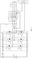
- FIG. 3 is a circuit diagram of another charging and discharging circuit according to an embodiment of this application.
- the charging and discharging circuit shown in FIG. 2 and the charging and discharging circuit shown in FIG. 3 are equivalent structures.
- a first bridge arm 2 includes a first switching transistor Q1 and a second switching transistor Q2
- a second bridge arm 3 includes a third switching transistor Q3 and a fourth switching transistor Q4
- a third bridge arm 4 includes a fifth switching transistor Q5 and a sixth switching transistor Q6.
- a second pin of the first switching transistor Q1 is connected to a first pin of the second switching transistor Q2
- a second pin of the third switching transistor Q3 is connected to a first pin of the fourth switching transistor Q4
- a second pin of the fifth switching transistor Q5 is connected to a first pin of the sixth switching transistor Q6.
- a first pin of the first switching transistor Q1, a first pin of the third switching transistor Q3, and a first pin of the fifth switching transistor Q5 are all connected to a positive output terminal of a battery 1 by using a first switch K1, and a second pin of the second switching transistor Q2, a second pin of the fourth switching transistor Q4, and a second pin of the sixth switching transistor Q6 are all connected to a negative output terminal of the battery 1.
- the second pin of the first switching transistor Q1 and the first pin of the second switching transistor Q2 are both connected to a first terminal a of a first inductor L1
- the second pin of the third switching transistor Q3 and the first pin of the fourth switching transistor Q4 are both connected to a first terminal c of a second inductor L2
- the second pin of the fifth switching transistor Q5 and the first pin of the sixth switching transistor Q6 are both connected to a first terminal e of a third inductor L3.
- the first switching transistor Q1, the second switching transistor Q2, the third switching transistor Q3, the fourth switching transistor Q4, the fifth switching transistor Q5, and the sixth switching transistor Q6 may be specifically implemented in a plurality of manners.
- the switching transistor shown in FIG. 3 may be an insulated gate bipolar transistor, the switching transistor shown in FIG. 3 may be made of silicon carbide, or the switching transistor shown in FIG. 3 may be a metal-oxide semiconductor field-effect transistor.
- the switching transistor shown in FIG. 3 is not limited thereto, and the switching transistor shown in FIG. 3 may be alternatively another switching semiconductor component or the like.
- FIG. 4 is a circuit diagram of still another charging and discharging circuit according to an embodiment of this application.
- the charging and discharging circuit further includes a first capacitor C1 and a second capacitor C2.
- a positive terminal of the first capacitor C1 is connected to a positive output terminal of a battery 1, and a negative terminal of the first capacitor C1 is connected to a negative output terminal of the battery 1.
- a positive terminal of the second capacitor C2 is connected to a first terminal of a first switch K1, a negative terminal of the second capacitor C2 is connected to the negative output terminal of the battery 1, and a second terminal of the first switch K1 is connected to the positive output terminal of the battery 1.
- the first switch K1, a second switch K2, a third switch K3, and a fourth switch K4 are all in a closed state
- a fifth switch S1, a sixth switch S2, a seventh switch S3, and an eighth switch S4 are all in an open state
- a first bridge arm 2, a second bridge arm 3, and a third bridge arm 4 constitute a direct current-alternating current converter
- a first inductor L1, a second inductor L2, and a third inductor L3 constitute a motor 5
- the first capacitor C1 and the second capacitor C2 are configured to filter input of the direct current-alternating current converter.
- the first switch K1, the second switch K2, the third switch K3, and the fourth switch K4 are all in an open state
- the fifth switch S1, the sixth switch S2, the seventh switch S3, and the eighth switch S4 are all in a closed state
- the first bridge arm 2, the third bridge arm 4, the first inductor L1, and the second inductor L2 constitute an alternating current-direct current converter
- the second bridge arm 3 and the third inductor L3 constitute a step-down circuit.
- a first charging interface 6 receives an alternating current provided by an external device, and sends the alternating current to the alternating current-direct current converter.
- the first capacitor C1 is configured to filter output of the step-down circuit.
- the second capacitor C2 is configured to filter output of the alternating current-direct current converter.
- FIG. 5 is a circuit diagram of still another charging and discharging circuit according to an embodiment of this application.
- the charging and discharging circuit shown in FIG. 4 and the charging and discharging circuit shown in FIG. 5 are equivalent structures.
- FIG. 6 is a circuit diagram of still another charging and discharging circuit according to an embodiment of this application.
- the charging and discharging circuit further includes a filtering module 7.
- a first input terminal of the filtering module 7 is connected to a first output terminal of a first charging interface 6, and a second input terminal of the filtering module 7 is connected to a second output terminal of the first charging interface 6.
- a first output terminal of the filtering module 7 is connected to a second terminal d of a second inductor L2 by using a seventh switch S3, and a second output terminal of the filtering module 7 is connected to a middle point of a third bridge arm 4.
- a first switch K1, a second switch K2, a third switch K3, and a fourth switch K4 are all in an open state
- a fifth switch S1, a sixth switch S2, the seventh switch S3, and an eighth switch S4 are all in a closed state
- a first bridge arm 2, the third bridge arm 4, a first inductor L1, and the second inductor L2 constitute an alternating current-direct current converter
- a second bridge arm 3 and a third inductor L3 constitute a step-down circuit.
- the first charging interface 6 receives an alternating current provided by an external device, and sends the alternating current to the alternating current-direct current converter.
- the filtering module 7 is configured to suppress high-frequency interference in the charging and discharging circuit.
- the filtering module 7 may be specifically an electromagnetic interference filter.
- FIG. 7 is a circuit diagram of still another charging and discharging circuit according to an embodiment of this application.
- the charging and discharging circuit shown in FIG. 6 and the charging and discharging circuit shown in FIG. 7 are equivalent structures.
- FIG. 8 is a circuit diagram of still another charging and discharging circuit according to an embodiment of this application.
- the charging and discharging circuit further includes a second charging interface 8 and a three-phase rectifier bridge arm 9.
- a first input terminal of the three-phase rectifier bridge arm 9 is connected to a first output terminal of the second charging interface 8
- a second input terminal of the three-phase rectifier bridge arm 9 is connected to a second output terminal of the second charging interface 8
- a third input terminal of the three-phase rectifier bridge arm 9 is connected to a third output terminal of the second charging interface 8.
- a first output terminal of the three-phase rectifier bridge arm 9 is connected to a first input terminal of a filtering module 7, and a second output terminal of the three-phase rectifier bridge arm 9 is connected to a second input terminal of the filtering module 7.
- a first switch K1, a second switch K2, a third switch K3, and a fourth switch K4 are all in an open state
- a fifth switch S1, a sixth switch S2, a seventh switch S3, and an eighth switch S4 are all in a closed state
- a first bridge arm 2, a third bridge arm 4, a first inductor L1, and a second inductor L2 constitute an alternating current-direct current converter
- a second bridge arm 3 and a third inductor L3 constitute a step-down circuit.
- the second charging interface 8 receives a three-phase alternating current provided by an external device, and sends the three-phase alternating current to the three-phase rectifier bridge arm 9.
- the three-phase rectifier bridge arm 9 converts the three-phase alternating current sent by the second charging interface 8 into a two-phase alternating current, and sends the two-phase alternating current to the filtering module 7.
- the second charging interface 8 is configured to receive the three-phase alternating current provided by the external device, and the three-phase rectifier bridge arm 9 is configured to convert the three-phase alternating current sent by the second charging interface 8 into the two-phase alternating current. Therefore, the charging and discharging circuit shown in FIG. 8 can implement not only two-phase charging but also three-phase charging.
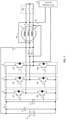
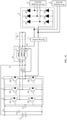
- FIG. 9 is a circuit diagram of still another charging and discharging circuit according to an embodiment of this application.
- a three-phase rectifier bridge arm 9 includes a first diode D1, a second diode D2, a third diode D3, a fourth diode D4, a fifth diode D5, and a sixth diode D6.
- a negative electrode of the first diode D1, a negative electrode of the third diode D3, and a negative electrode of the fifth diode D5 are all connected to a first input terminal of a filtering module 7, and a positive electrode of the second diode D2, a positive electrode of the fourth diode D4, and a positive electrode of the sixth diode D6 are all connected to a second input terminal of the filtering module 7.
- a positive electrode of the first diode D1 and a negative electrode of the second diode D2 are both connected to a first output terminal of a second charging interface 8
- a positive electrode of the third diode D3 and a negative electrode of the fourth diode D4 are both connected to a second output terminal of the second charging interface 8
- a positive electrode of the fifth diode D5 and a negative electrode of the sixth diode D6 are both connected to a third output terminal of the second charging interface 8.
- the three-phase rectifier bridge arm 9 is not limited to the structure shown in FIG. 9 , and may be alternatively of another structure.
- FIG. 10 is a circuit diagram of still another charging and discharging circuit according to an embodiment of this application.
- the charging and discharging circuit shown in FIG. 9 and the charging and discharging circuit shown in FIG. 10 are equivalent structures.
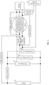
- FIG. 11 is a circuit diagram of a charging and discharging system according to an embodiment of this application.
- the charging and discharging system includes a charging and discharging circuit and a controller 10, and the charging and discharging circuit includes a battery 1, a motor 5, a first charging interface 6, a first bridge arm 2, a second bridge arm 3, a third bridge arm 4, a first switch K1, a second switch K2, a third switch K3, a fourth switch K4, a fifth switch S1, a sixth switch S2, a seventh switch S3, and an eighth switch S4.
- the controller 10 is separately connected to a control terminal of the first switch K1, a control terminal of the second switch K2, a control terminal of the third switch K3, a control terminal of the fourth switch K4, a control terminal of the fifth switch S1, a control terminal of the sixth switch S2, a control terminal of the seventh switch S3, and a control terminal of the eighth switch S4.
- a positive output terminal of the battery 1 is separately connected to a positive terminal of the first bridge arm 2, a positive terminal of the second bridge arm 3, and a positive terminal of the third bridge arm 4 by using the first switch K1, and a negative output terminal of the battery 1 is separately connected to a negative terminal of the first bridge arm 2, a negative terminal of the second bridge arm 3, and a negative terminal of the third bridge arm 4.
- the motor 5 includes a first inductor L1, a second inductor L2, and a third inductor L3, a first terminal a of the first inductor L1 is connected to a middle point of the first bridge arm 2, a first terminal c of the second inductor L2 is connected to a middle point of the second bridge arm 3, a first terminal e of the third inductor L3 is connected to a middle point of the third bridge arm 4, and a second terminal b of the first inductor L1, a second terminal d of the second inductor L2, and a second terminal f of the third inductor L3 are connected to a first terminal of the fourth switch K4.
- a first output terminal of the first charging interface 6 is connected to the second terminal d of the second inductor L2, and a second output terminal of the first charging interface 6 is connected to the middle point of the third bridge arm 4.
- the second switch K2 is disposed between the middle point of the second bridge arm 3 and the first terminal c of the second inductor L2
- the third switch K3 is disposed between the middle point of the third bridge arm 4 and the first terminal e of the third inductor L3
- the fifth switch S1 is disposed between the positive output terminal of the battery 1 and the first terminal e of the third inductor L3
- the sixth switch S2 is disposed between the middle point of the second bridge arm 3 and the second terminal f of the third inductor L3
- the seventh switch S3 is disposed between the first output terminal of the first charging interface 6 and the second terminal d of the second inductor L2
- the eighth switch S4 is disposed between the first terminal c of the second inductor L2 and the second terminal b of the first in
- the controller 10 when the controller 10 receives a control signal of a driving mode, the controller 10 separately sends close signals to the first switch K1, the second switch K2, the third switch K3, and the fourth switch K4, and separately sends open signals to the fifth switch S1, the sixth switch S2, the seventh switch S3, and the eighth switch S4.
- the first switch K1, the second switch K2, the third switch K3, and the fourth switch K4 are all in a closed state
- the fifth switch S1, the sixth switch S2, the seventh switch S3, and the eighth switch S4 are all in an open state
- the first bridge arm 2, the second bridge arm 3, and the third bridge arm 4 constitute a direct current-alternating current converter
- the first inductor L1, the second inductor L2, and the third inductor L3 constitute the motor 5.
- the battery 1 provides a direct current for the direct current-alternating current converter, and the direct current-alternating current converter converts the direct current provided by the battery 1 into an alternating current and sends the alternating current to the motor 5.
- the motor 5 receives the alternating current sent by the direct current-alternating current converter, the motor 5 starts to run.
- the controller 10 when the controller 10 receives a control signal of a charging mode, the controller 10 separately sends open signals to the first switch K1, the second switch K2, the third switch K3, and the fourth switch K4, and separately sends close signals to the fifth switch S1, the sixth switch S2, the seventh switch S3, and the eighth switch S4.
- the first switch K1, the second switch K2, the third switch K3, and the fourth switch K4 are all in an open state
- the fifth switch S1, the sixth switch S2, the seventh switch S3, and the eighth switch S4 are all in a closed state
- the first bridge arm 2, the third bridge arm 4, the first inductor L1, and the second inductor L2 constitute an alternating current-direct current converter
- the second bridge arm 3 and the third inductor L3 constitute a step-down circuit.
- the first charging interface 6 receives an alternating current provided by an external device, and sends the alternating current to the alternating current-direct current converter.
- the alternating current-direct current converter converts the alternating current provided by the first charging interface 6 into a high-voltage direct current, and sends the high-voltage direct current to the step-down circuit.
- the step-down circuit performs step-down processing on the high-voltage direct current provided by the alternating current-direct current converter, to obtain a low-voltage direct current, and sends the low-voltage direct current to the battery 1, to charge the battery 1.
- the charging and discharging circuit may be alternatively any one of the charging and discharging circuits shown in FIG. 3 to FIG. 10 .
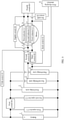
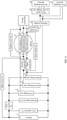
- FIG. 12 is a circuit diagram of an electric vehicle 200 according to an embodiment of this application.
- the electric vehicle 200 shown in FIG. 12 includes a charging and discharging system 201, a transmission system 202, a direct current converter 203, an air conditioning system 204, and a low-voltage system 205.
- a first output terminal of the charging and discharging system 201 is connected to the transmission system 202
- a second output terminal of the charging and discharging system 201 is connected to an input terminal of the direct current converter 203
- a third output terminal of the charging and discharging system 201 is connected to the air conditioning system 204.
- An output terminal of the direct current converter 203 is connected to the low-voltage system 205.
- a charging system 300 may be a charging pile, and the charging system 300 may be alternatively an external charger of the electric vehicle.
- the charging and discharging system 201 shown in FIG. 12 may be the charging and discharging system shown in FIG. 11 .
- the controller 10 when the electric vehicle 200 is in a driving mode, the controller 10 separately sends close signals to the first switch K1, the second switch K2, the third switch K3, and the fourth switch K4, and separately sends open signals to the fifth switch S1, the sixth switch S2, the seventh switch S3, and the eighth switch S4.
- the first switch K1, the second switch K2, the third switch K3, and the fourth switch K4 are all in a closed state
- the fifth switch S1, the sixth switch S2, the seventh switch S3, and the eighth switch S4 are all in an open state
- the first bridge arm 2, the second bridge arm 3, and the third bridge arm 4 constitute a direct current-alternating current converter
- the first inductor L1, the second inductor L2, and the third inductor L3 constitute the motor 5.
- the battery 1 of the charging and discharging system 201 provides a direct current for the direct current-alternating current converter, and the direct current-alternating current converter converts the direct current provided by the battery 1 into an alternating current and sends the alternating current to the motor 5.
- the motor 5 receives the alternating current sent by the direct current-alternating current converter, the motor 5 starts to run.
- the battery 1 further provides a high-voltage direct current for the transmission system 202, the direct current converter 203, and the air conditioning system 204.
- the transmission system 202 transmits power provided by the motor 5 to wheels of the electric vehicle.
- the air conditioning system 204 receives the high-voltage direct current provided by the battery 1, the air conditioning system 204 starts to run.
- the direct current converter 203 receives the high-voltage direct current provided by the battery 1
- the direct current converter 203 converts the high-voltage direct current into a low-voltage direct current and sends the low-voltage direct current to the low-voltage system 205.
- the low-voltage system 205 receives the low-voltage direct current provided by the direct current converter 203, all components in the low-voltage system 205 start to run.
- the low-voltage system 205 includes a light system, a central control system, an instrument system, a wiper system, a glass lifting system, a water pump system, and the like.
- the controller 10 when the electric vehicle 200 is in a charging mode, the controller 10 separately sends open signals to the first switch K1, the second switch K2, the third switch K3, and the fourth switch K4, and separately sends close signals to the fifth switch S1, the sixth switch S2, the seventh switch S3, and the eighth switch S4.
- the first switch K1, the second switch K2, the third switch K3, and the fourth switch K4 are all in an open state
- the fifth switch S1, the sixth switch S2, the seventh switch S3, and the eighth switch S4 are all in a closed state
- the first bridge arm 2, the third bridge arm 4, the first inductor L1, and the second inductor L2 constitute an alternating current-direct current converter
- the second bridge arm 3 and the third inductor L3 constitute a step-down circuit.
- the first charging interface 6 of the charging and discharging system 201 receives an alternating current provided by the charging system 300, and sends the alternating current to the alternating current-direct current converter.
- the alternating current-direct current converter converts the alternating current provided by the first charging interface 6 into a high-voltage direct current, and sends the high-voltage direct current to the step-down circuit.
- the step-down circuit performs step-down processing on the high-voltage direct current provided by the alternating current-direct current converter, to obtain a low-voltage direct current, and sends the low-voltage direct current to the battery 1, to charge the battery 1.
Landscapes
- Engineering & Computer Science (AREA)
- Power Engineering (AREA)
- Transportation (AREA)
- Mechanical Engineering (AREA)
- Manufacturing & Machinery (AREA)
- Chemical & Material Sciences (AREA)
- Chemical Kinetics & Catalysis (AREA)
- Electrochemistry (AREA)
- General Chemical & Material Sciences (AREA)
- Charge And Discharge Circuits For Batteries Or The Like (AREA)
Applications Claiming Priority (2)
| Application Number | Priority Date | Filing Date | Title |
|---|---|---|---|
| CN201910860488.8A CN110562058B (zh) | 2019-09-11 | 2019-09-11 | 一种充放电电路、系统和电动汽车 |
| PCT/CN2020/095122 WO2021047221A1 (fr) | 2019-09-11 | 2020-06-09 | Circuit et système de charge-décharge, et véhicule électrique |
Publications (2)
| Publication Number | Publication Date |
|---|---|
| EP3971018A1 true EP3971018A1 (fr) | 2022-03-23 |
| EP3971018A4 EP3971018A4 (fr) | 2022-07-27 |
Family
ID=68779372
Family Applications (1)
| Application Number | Title | Priority Date | Filing Date |
|---|---|---|---|
| EP20862783.6A Pending EP3971018A4 (fr) | 2019-09-11 | 2020-06-09 | Circuit et système de charge-décharge, et véhicule électrique |
Country Status (3)
| Country | Link |
|---|---|
| EP (1) | EP3971018A4 (fr) |
| CN (1) | CN110562058B (fr) |
| WO (1) | WO2021047221A1 (fr) |
Families Citing this family (4)
| Publication number | Priority date | Publication date | Assignee | Title |
|---|---|---|---|---|
| CN110562058B (zh) * | 2019-09-11 | 2022-08-19 | 华为数字能源技术有限公司 | 一种充放电电路、系统和电动汽车 |
| DE102019215052A1 (de) * | 2019-09-30 | 2021-04-01 | Robert Bosch Gmbh | Ladevorrichtung und Verfahren zum Laden eines elektrischen Energiespeichers |
| CN114290927B (zh) * | 2021-03-31 | 2024-04-12 | 华为数字能源技术有限公司 | 一种能量转换装置、动力系统及车辆 |
| CN118269765A (zh) * | 2023-10-31 | 2024-07-02 | 比亚迪股份有限公司 | 一种控制方法、电池系统及供电系统 |
Family Cites Families (12)
| Publication number | Priority date | Publication date | Assignee | Title |
|---|---|---|---|---|
| FR2946473B1 (fr) * | 2009-06-09 | 2011-08-19 | Renault Sas | Ensemble electromoteur rechargeable a partir d'un reseau electrique, et boitier de connexion dedie. |
| KR101191738B1 (ko) * | 2010-07-22 | 2012-10-15 | 재단법인 포항산업과학연구원 | 전력 변환 장치 |
| KR20120116722A (ko) * | 2011-04-13 | 2012-10-23 | 엘지전자 주식회사 | 전기 자동차 및 이의 구동 방법 |
| JP2015198499A (ja) * | 2014-04-01 | 2015-11-09 | 富士電機株式会社 | 電動機駆動装置 |
| KR101684064B1 (ko) * | 2015-02-12 | 2016-12-07 | 현대자동차주식회사 | 전기 자동차의 충전 시스템 |
| EP3347963A4 (fr) * | 2015-09-11 | 2019-01-16 | Invertedpower Pty Ltd | Contrôleur pour charge inductive ayant un ou plusieurs enroulements inductifs |
| JP6341238B2 (ja) * | 2016-07-29 | 2018-06-13 | トヨタ自動車株式会社 | 自動車 |
| CN107627881B (zh) * | 2017-09-18 | 2020-11-17 | 电子科技大学 | 一种电动汽车的充放电及电机驱动一体化装置 |
| CN107846055A (zh) * | 2017-10-31 | 2018-03-27 | 华为技术有限公司 | 电动汽车的充放电电路及方法 |
| CN109361255B (zh) * | 2018-10-19 | 2021-02-05 | 南京航空航天大学 | 一种基于电机绕组开路的充放电电路拓扑 |
| CN109889077B (zh) * | 2019-04-08 | 2021-01-26 | 台达电子企业管理(上海)有限公司 | 单相和三相兼容的ac/dc电路及充放电装置 |
| CN110562058B (zh) * | 2019-09-11 | 2022-08-19 | 华为数字能源技术有限公司 | 一种充放电电路、系统和电动汽车 |
-
2019
- 2019-09-11 CN CN201910860488.8A patent/CN110562058B/zh active Active
-
2020
- 2020-06-09 WO PCT/CN2020/095122 patent/WO2021047221A1/fr not_active Ceased
- 2020-06-09 EP EP20862783.6A patent/EP3971018A4/fr active Pending
Also Published As
| Publication number | Publication date |
|---|---|
| CN110562058B (zh) | 2022-08-19 |
| CN110562058A (zh) | 2019-12-13 |
| WO2021047221A1 (fr) | 2021-03-18 |
| EP3971018A4 (fr) | 2022-07-27 |
Similar Documents
| Publication | Publication Date | Title |
|---|---|---|
| EP3971018A1 (fr) | Circuit et système de charge-décharge, et véhicule électrique | |
| CN110356268B (zh) | 一种车载充放电装置和系统 | |
| EP3886304A1 (fr) | Chargeur embarqué | |
| EP3787169A1 (fr) | Convertisseur cc-cc, chargeur monté dans un véhicule et véhicule électrique | |
| EP3950411A1 (fr) | Circuit cc/cc de chargeur embarqué, chargeur embarqué, automobile à nouvelle énergie et pile de charge | |
| US11677328B2 (en) | Converter and power supply system with simplified sampling | |
| US20180170193A1 (en) | Multi-functional on-vehicle power converter and electric vehicle comprising the same | |
| EP2887491A1 (fr) | Dispositif de conversion d'alimentation électrique pour le chargement de batteries | |
| CN106936184A (zh) | 一种车载充电机和dcdc的集成电路 | |
| CN106160143A (zh) | 电动汽车的车载充电装置和电动汽车 | |
| US11142092B2 (en) | Power supply system for vehicle | |
| EP4207569A1 (fr) | Convertisseur cc/cc et procédé et système de changement de gain de tension | |
| CN112776632A (zh) | 用于电动和/或混合动力车辆的宽电压范围功率转换系统 | |
| CN112072765A (zh) | 一种基于最小视在功率模块的混合充电系统和设计方法 | |
| EP4231494A1 (fr) | Circuit de conversion et appareil de charge | |
| CN107437800A (zh) | 车载滤波装置、车载充电设备和车辆 | |
| CN212627278U (zh) | 一种充电电路及车用充电设备 | |
| CN208401600U (zh) | 一种双向充电机及电动汽车 | |
| EP4507178A1 (fr) | Convertisseur de courant continu-continu et dispositif électronique | |
| CN206341153U (zh) | 用于电动汽车的车载功率变换器和包含其的电动汽车 | |
| CN107150607A (zh) | 一种智能充电器 | |
| CN211629884U (zh) | 电动汽车的充电电路及交流充电设备 | |
| CN110323947A (zh) | 一种dc-dc变换器 | |
| CN209250280U (zh) | 一种用于直流微电网的中压柔性直流双向变换装置 | |
| CN111884307A (zh) | 一种充电电路及车用充电设备 |
Legal Events
| Date | Code | Title | Description |
|---|---|---|---|
| STAA | Information on the status of an ep patent application or granted ep patent |
Free format text: STATUS: THE INTERNATIONAL PUBLICATION HAS BEEN MADE |
|
| PUAI | Public reference made under article 153(3) epc to a published international application that has entered the european phase |
Free format text: ORIGINAL CODE: 0009012 |
|
| STAA | Information on the status of an ep patent application or granted ep patent |
Free format text: STATUS: REQUEST FOR EXAMINATION WAS MADE |
|
| 17P | Request for examination filed |
Effective date: 20211217 |
|
| AK | Designated contracting states |
Kind code of ref document: A1 Designated state(s): AL AT BE BG CH CY CZ DE DK EE ES FI FR GB GR HR HU IE IS IT LI LT LU LV MC MK MT NL NO PL PT RO RS SE SI SK SM TR |
|
| REG | Reference to a national code |
Ref country code: DE Ref legal event code: R079 Free format text: PREVIOUS MAIN CLASS: B60L0053000000 Ipc: B60L0053240000 |
|
| A4 | Supplementary search report drawn up and despatched |
Effective date: 20220629 |
|
| RIC1 | Information provided on ipc code assigned before grant |
Ipc: B60L 53/20 20190101ALI20220623BHEP Ipc: H01M 10/44 20060101ALI20220623BHEP Ipc: H02P 27/06 20060101ALI20220623BHEP Ipc: H02J 7/04 20060101ALI20220623BHEP Ipc: B60L 53/24 20190101AFI20220623BHEP |
|
| DAV | Request for validation of the european patent (deleted) | ||
| DAX | Request for extension of the european patent (deleted) | ||
| STAA | Information on the status of an ep patent application or granted ep patent |
Free format text: STATUS: EXAMINATION IS IN PROGRESS |
|
| 17Q | First examination report despatched |
Effective date: 20251212 |