EP3971374A2 - Sécurité de verrouillage pour une bouteille - Google Patents
Sécurité de verrouillage pour une bouteille Download PDFInfo
- Publication number
- EP3971374A2 EP3971374A2 EP21195120.7A EP21195120A EP3971374A2 EP 3971374 A2 EP3971374 A2 EP 3971374A2 EP 21195120 A EP21195120 A EP 21195120A EP 3971374 A2 EP3971374 A2 EP 3971374A2
- Authority
- EP
- European Patent Office
- Prior art keywords
- locking device
- state
- bottle
- secured
- release
- Prior art date
- Legal status (The legal status is an assumption and is not a legal conclusion. Google has not performed a legal analysis and makes no representation as to the accuracy of the status listed.)
- Pending
Links
- 210000000078 claw Anatomy 0.000 claims abstract description 74
- 230000007246 mechanism Effects 0.000 claims abstract description 44
- 230000000903 blocking effect Effects 0.000 claims description 21
- 238000013461 design Methods 0.000 claims description 10
- 239000002184 metal Substances 0.000 claims description 4
- 238000000034 method Methods 0.000 claims description 4
- 230000004888 barrier function Effects 0.000 claims description 3
- 238000012544 monitoring process Methods 0.000 claims description 2
- 229910001285 shape-memory alloy Inorganic materials 0.000 claims description 2
- 230000008901 benefit Effects 0.000 description 3
- 238000011161 development Methods 0.000 description 2
- 230000000977 initiatory effect Effects 0.000 description 2
- 238000012546 transfer Methods 0.000 description 2
- 230000009471 action Effects 0.000 description 1
- 239000011324 bead Substances 0.000 description 1
- 230000006835 compression Effects 0.000 description 1
- 238000007906 compression Methods 0.000 description 1
- 230000008878 coupling Effects 0.000 description 1
- 238000010168 coupling process Methods 0.000 description 1
- 238000005859 coupling reaction Methods 0.000 description 1
- 230000002950 deficient Effects 0.000 description 1
- 238000006073 displacement reaction Methods 0.000 description 1
- 230000000694 effects Effects 0.000 description 1
- 230000005670 electromagnetic radiation Effects 0.000 description 1
- 238000012423 maintenance Methods 0.000 description 1
- 230000003287 optical effect Effects 0.000 description 1
- 230000001960 triggered effect Effects 0.000 description 1
Images


Classifications
-
- E—FIXED CONSTRUCTIONS
- E05—LOCKS; KEYS; WINDOW OR DOOR FITTINGS; SAFES
- E05B—LOCKS; ACCESSORIES THEREFOR; HANDCUFFS
- E05B73/00—Devices for locking portable objects against unauthorised removal; Miscellaneous locking devices
- E05B73/0017—Anti-theft devices, e.g. tags or monitors, fixed to articles, e.g. clothes, and to be removed at the check-out of shops
- E05B73/0041—Anti-theft devices, e.g. tags or monitors, fixed to articles, e.g. clothes, and to be removed at the check-out of shops for essentially round objects, e.g. bottles or racket handles
-
- B—PERFORMING OPERATIONS; TRANSPORTING
- B65—CONVEYING; PACKING; STORING; HANDLING THIN OR FILAMENTARY MATERIAL
- B65D—CONTAINERS FOR STORAGE OR TRANSPORT OF ARTICLES OR MATERIALS, e.g. BAGS, BARRELS, BOTTLES, BOXES, CANS, CARTONS, CRATES, DRUMS, JARS, TANKS, HOPPERS, FORWARDING CONTAINERS; ACCESSORIES, CLOSURES, OR FITTINGS THEREFOR; PACKAGING ELEMENTS; PACKAGES
- B65D55/00—Accessories for container closures not otherwise provided for
- B65D55/02—Locking devices; Means for discouraging or indicating unauthorised opening or removal of closure
- B65D55/14—Applications of locks, e.g. of permutation or key-controlled locks
-
- E—FIXED CONSTRUCTIONS
- E05—LOCKS; KEYS; WINDOW OR DOOR FITTINGS; SAFES
- E05B—LOCKS; ACCESSORIES THEREFOR; HANDCUFFS
- E05B63/00—Locks or fastenings with special structural characteristics
- E05B63/0056—Locks with adjustable or exchangeable lock parts
-
- E—FIXED CONSTRUCTIONS
- E05—LOCKS; KEYS; WINDOW OR DOOR FITTINGS; SAFES
- E05B—LOCKS; ACCESSORIES THEREFOR; HANDCUFFS
- E05B47/00—Operating or controlling locks or other fastening devices by electric or magnetic means
- E05B2047/0048—Circuits, feeding, monitoring
- E05B2047/0067—Monitoring
Definitions
- the invention relates to a locking device for a bottle, comprising a housing part which is designed to enclose an upper section of the bottle neck of the bottle to be secured, including the bottle cap of the locking device, a plurality of claws arranged in the housing part, which are designed and intended to in a locking state of the locking device to undetachably engage the top portion of the bottle neck and in a released state of the locking device to allow the locking device to be loosened and removed away from the top portion of the bottle neck, and a locking mechanism which is configured and intended to assume an unlocked state , in which the locking device can be transferred from the secured state to the released state, and to assume a locked state in which the locking device cannot be moved from the secured state to the released state stand is transferrable.
- such generic locking devices have on the one hand an anti-theft element, for example an RFID chip or an EAS element (electronic article surveillance), which is set up to interact with an external anti-theft system, for example a transmitter/receiver unit for electromagnetic radiation of a suitable wavelength , so that when the locking device equipped with the RFID chip or the EAS element is passed, a signal is generated and an alarm can be triggered.
- an anti-theft element for example an RFID chip or an EAS element (electronic article surveillance)
- an external anti-theft system for example a transmitter/receiver unit for electromagnetic radiation of a suitable wavelength
- a locking mechanism is generally also provided on generic locking devices, which is designed and intended to, in a locked state, ie a secured state of the locking mechanism, essentially to ensure non-detachable engagement between the locking device and the bottle to be secured.
- the object is achieved by a locking device of the type mentioned at the outset, in which the plurality of claws is divided at least into a first and a second claw arrangement, with each claw arrangement being assigned a part of the plurality of claws, with the first claw arrangement differs from the second claw arrangement with regard to at least one claw design feature.
- the difference can only consist in the expression of a respective claw design feature.
- the first claw arrangement to include a claw design feature that the second claw arrangement does not include, which can be, for example, a projection and/or a depression and/or the like.
- a multiplicity of different bottle types can be secured with a single closure securing device, which differ, for example, with regard to a diameter and/or a bottle neck length and/or a bottle neck shape and/or a closure.
- the difference can only consist in the expression of a respective design feature.
- the first claw arrangement to include a design feature that the second claw arrangement does not include, which can be, for example, a projection and/or a depression and/or the like.
- a multiplicity of different bottle types can be secured with a single closure securing device, which differ, for example, with regard to a diameter and/or a bottle neck length and/or a bottle neck shape and/or a closure.
- the claws can act according to the principle of a barb and, for example, interact with a bead on the bottle neck in the secured state of the locking device in such a way that the locking device is prevented from being pulled off the bottle neck.
- the at least one design feature can correspond to a length and/or a width and/or an angle and/or a shape of the claws.
- the first claw arrangement and/or the second claw arrangement each consist of a plurality, preferably along one direction of attachment the locking device, is formed in a row arranged claws.
- the first claw arrangement and the second claw arrangement can be arranged adjacent to one another, preferably in an alternating manner, along a circumferential direction of the housing part.
- the claws themselves can be deformable, which ensures that they can be adapted to different bottle types.
- at least some of the plurality of claws may be attached in a displaceable or pivotable manner to the housing or a part connected thereto and by an elastic element, e.g. a spring, in particular a spiral spring, towards the bottle neck be biased.
- an elastic element e.g. a spring, in particular a spiral spring
- the housing can comprise at least a first housing part and a second housing part, which are connected to one another so that they can be moved relative to one another and between the securing state in which the majority of claws of the locking device engages with the upper section of the bottle neck in a non-detachable manner, and can be transferred to the release state in which the locking device can be released from the bottle neck.
- the locking mechanism can be assigned to one of the first and the second housing part and set up to lock the first and the second housing part in the secured state.
- the first and the second housing part can be present as two separate components when the locking device is in the released state.
- the first and second housing parts be connected to one another by a hinge in a manner that can be pivoted relative to one another, with preferably a Pivot axis of the hinge is arranged in the secured state above the bottle neck or parallel to it.
- first and second housing parts be secured by a second elastic element, for example a spring, in particular a coil spring, are biased to their release condition.
- a second elastic element for example a spring, in particular a coil spring
- the locking mechanism has an actuating element which can be displaced between a release position and a securing position, a blocking element which is operatively connected to the actuating element and which in the securing position of the actuating element engages the other of the first and second housing parts to fix the two housing parts in their relative alignment, and comprises a release element, which is associated with the actuating element and is arranged in the locked state of the locking mechanism to prevent movement of the actuating element from the secured position into to block the release position and, in the unlocked state of the locking mechanism, to allow movement of the actuating element from the secured position to the released position.
- a locking device of the type mentioned at the beginning which comprises an insert section which is designed and intended to be inserted into the housing part of the locking device, wherein the plurality of claws are attached to or comprised by the insert portion.
- the manufacturability of the locking device can be improved, since a large number of different variants of locking devices can be produced for a large number of different bottle types, with only a separate insert section having to be produced in each case , but otherwise an identical housing and locking mechanism can be used.
- the insert section is also designed and intended to be inserted into the housing part in a detachable manner.
- the insert section can be designed to be exchangeable for reasons of purpose or wear and tear, which not only increases the ease of maintenance of the locking device according to the invention.
- the invention also relates to a kit comprising at least one locking device according to the invention according to the second aspect with at least two of the insert sections described above.
- a locking device for a bottle comprising a first and a second housing part, which are designed to cover an upper section of the the bottleneck of the bottle to be secured, including the bottle cap, in a non-detachable manner in a secured state, with the first and second housing parts being connected to one another so that they can be moved relative to one another and being transferrable between the secured state and a release state in which the closure safety device can be detached from the bottleneck, and a locking mechanism associated with and configured for one of the first and second housing parts is to lock the first and the second housing part in the secured state, with the locking mechanism having an actuating element which can be displaced between a release position and a securing position, a blocking element which is operatively connected to the actuating element and which, in the securing position of the actuating element, can be connected to the other of the first and engages the second housing part in order
- the blocking element can be aligned at an angle of 70° to 110°, preferably at an angle of approximately 90° relative to the actuating element and/or a direction of movement of the actuating element.
- the design of the locking mechanism according to the invention has the consequence that the force holding the two housing parts in the secured state is not provided by the actuating element itself, but by the blocking element.
- the blocking element is preferably also arranged in such a way that it is stressed in the tension/compression direction. As a result, the durability of the locking mechanism can be significantly increased over known locking mechanisms.
- the locking element as an elongated strip of sheet metal, which is preferably at least partially Plastic is encased, and / or be formed entirely of plastic substantially. This ensures sufficient resilience together with sufficient deformability of the blocking element.
- the other of the first and second housing parts comprises a recess which is designed and intended to interact with the locking element.
- the actuating element is movably connected to the blocking element, one end of the actuating element preferably being designed as a pin and/or nail-shaped and/or the blocking element being fork-shaped.
- the release element can be designed as a slide which has an opening through which the actuating element is guided, and/or the release element can be displaced essentially orthogonally to a direction of movement of the actuating element in order to selectively block or block the movement of the actuating element to release.
- the release element In the locked state of the locking mechanism, the release element can engage with the actuating element, preferably in a form-fitting manner, in such a way that movement of the actuating element from the securing position into the release position is prevented, and in the unlocked state of the locking mechanism with the actuating element, except Be brought into engagement that movement of the actuating element is allowed from the securing position to the release position.
- the release element has a projection which is designed and intended for this purpose, when the locking device is transferred to the locking state, with a to cooperate on the other further projection formed from the first and the second housing part in such a way that the release element releases the movement of the actuating element in the direction of its release position.
- the actuating element can be preloaded to its release position by a third elastic element, for example a spring, in particular a spiral spring be.
- the release element can be actuated mechanically and/or magnetically.
- the actuation can also be carried out remotely, for example, it is advantageous for the locking mechanism to also include an actuator which is operatively coupled to the release element, the actuator preferably at least partially formed by a shape memory alloy and/or a piezoelectric element.
- a locking device for a bottle comprising a housing part which is designed to cover an upper section of the bottleneck of the bottle to be secured to enclose the bottle including the bottle cap of the closure device, a plurality of claws arranged in the housing part, which are designed and intended to engage in a secured state of the closure device with the upper section of the bottle neck and in a release state of the closure device, release and removal of the closure device off the top portion of the bottle neck, and a locking mechanism adapted and intended to move the closure safeguard from the secured condition to the release condition and from the released condition to the secure condition s state
- the locking device further comprises a first sensor unit, which is designed to detect whether the locking device is in the locking state or in the release state, and a second sensor unit, which is designed to detect whether the upper Section of the bottleneck of the bottle to be secured is enclosed or not.
- the locking device can be put into a sleep mode to save energy, for example, when the Locking device, preferably longer than a predetermined period of time, is in the release state. If the locking device is then closed again, ie transferred to the release state, the locking device can be put back into an active mode.
- the second sensor unit can also detect whether the locking device is located on the upper section of the bottleneck of the bottle to be secured, the locking device can be put into an alarm mode, preferably automatically, as soon as it is attached to the bottle. If the locking device is removed from the bottle in the alarm mode without first being unlocked, for example by receiving a release signal or the like, a corresponding acoustic or optical alarm signal can be emitted.
- the first sensor unit and/or the second sensor unit can preferably include a light barrier and/or an ultrasonic sensor and/or a magnetic sensor and/or a pushbutton switch and/or a Hall sensor.
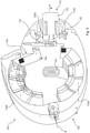
- a locking device according to the invention is generally denoted by 100 .
- the locking device according to the invention comprises a housing part 102 which is designed to enclose an upper section of a bottle neck H of a bottle F to be secured.
- the locking device 100 also includes a plurality of claws 104, which in the exemplary embodiment shown are designed in the form of a plurality of barbs.
- the housing 102 of the locking device 100 is designed as a two-part housing which comprises a first housing part 102a and a second housing part 102b.
- the first housing part 102a and the second housing part 102b are connected to one another by a hinge 106 so that they can pivot about a pivot axis S.
- the first housing part 102a and the second housing part 102b can be brought into the release state, ie the in 2 be biased open position shown.
- the locking device 100 also includes a locking mechanism 110 which, in the exemplary embodiment shown, is associated with the housing part 102a or is arranged on it.
- the locking mechanism 110 is configured and intended to assume a locked state in which the relative pivotal movement of the two housing parts 102a and 102b from the secured state to the released state is prevented, and to assume an unlocked state in which the pivotal movement of the two housing parts 102a and 102b from the save state to the enable state is allowed.
- the locking mechanism 110 will be described in more detail below.
- FIG. 12 now shows a perspective view of the housing part 102b of the locking device 100 2 .
- the housing part 102b comprises a plurality of claws 104 arranged thereon, which are divided into a first claw arrangement 104a and a second claw arrangement 104b.
- the claws of the first claw arrangement 104a differ in their design from the claws of the second claw arrangement 104b.
- both the first claw arrangement 104a and the second claw arrangement 104b are each formed from a plurality of claws 104 arranged in a row along a connection direction A of the locking device 100 .
- the first claw arrangement 104a and the second claw arrangement 104b are arranged in an alternating manner adjacent to one another in the circumferential direction. It should also be pointed out at this point that the housing 102 can also include further claws or claw arrangements, which essentially correspond to the claw arrangements 104a or 104b, which are not shown here for the sake of simplicity.
- the claws 104 can be mounted in a displaceable or pivoting manner on the housing 102 and can be biased towards the bottle neck H by another spring, for example a coil spring.
- the locking device 100 further comprises an insert section 108, which in the exemplary embodiment shown is formed by an insert subsection 108a assigned to the first housing part 102a and an insert subsection 108b assigned to the second housing part 102b (see, for example, FIG.2 ).
- claws 104 are attached to insert portions 108a and 108b.
- the insert sections 108a and 108b can preferably be removed from the housing 102, ie the housing part 102a and 102b, and reinserted, so that the locking device 100 can be provided with different claw arrangements if desired or a defective claw arrangement can be replaced if worn.
- the insert sections 108a and 108b are shown in 2 only shown with dashed lines.
- the locking mechanism 110 comprises an actuating element 112 which, in the exemplary embodiment shown, is designed as an actuating button supported by a spring 114 .
- a free end 112a of the actuating element 112 is operatively connected to a blocking element 116, which in the exemplary embodiment shown is designed as an elongate sheet metal strip.
- a front end of the locking element 116 is covered with a cap 118 made of plastic.
- the actuating element 112 is shown in its secured position, which causes the blocking element 116 to be locked with an in recess 120 formed in housing part 102b in order to fix the two housing parts 102a and 102b in their relative orientation about pivot axis S.
- FIG 5 shows the locking device 100 4 , which has been transferred to the enable state.
- the actuating element 112 is moved out of the housing part 102a along an actuating direction B, so that the blocking element 116 operatively connected to the end 112a is disengaged from the recess of the housing part 102b.
- the housing part 102b can be pivoted about the pivot axis S, preferably supported by a spring, and the locking device can be transferred to the release state.
- a release element in the form of a slide 122 is also provided, which has an opening 122a through which the actuating element 112 is guided substantially transversely to its direction of movement B.
- the slide 122 is displaced essentially orthogonally to the direction of movement B or orthogonally to the plane of the drawing, whereby the blockage acting on the actuating element 112 by the slide 122 is removed and the actuating element 112 moves along its direction of movement B into the figure 5 shown release position can move.
- FIGS. 6a, 6b and 6c once again show several perspective views of locking element 116, which in the exemplary embodiment shown is formed as an elongated sheet metal strip, and of actuating element 112.
- the locking element 116 has a fork shape, in which the end 112a of the actuating element 112, which is nail-shaped in the illustrated embodiment, is rotatably inserted.
- the fork-shaped end of the blocking element 116 is also provided with the plastic sheathing 118 already mentioned briefly above. At this point, however, it should be pointed out that if desired, the entire blocking element 116 can also be made of plastic.
- 7 shows the slide 122 with the previously described opening 122a, through which the actuating element 112 is guided transversely to its direction of movement B.
- the slide 122 also comprises an engagement section 122b which engages with an engagement groove (not shown) formed on the slide 122 .
- the slide 122 is also connected to an actuator 124, which is also accommodated in the housing part 102a, but is only shown as a black box in the figure shown for the sake of simplicity.
- the actuator 124 includes two shape memory wires 124a and 124b, which are connected to the actuator 124 at one end and to a free end of the slide 122 at the other end.
- the wires 124a and 124b are heated by the actuator 124, they contract, resulting in a displacement of the slider 122 along the R direction.
- the engagement between the engaging portion 122b and the groove of the operating member 112 is released, whereby the operating member 112 can be transferred to its release position.
- the actuator 124 is operatively connected to an energy supply unit 126, which can be embodied as a battery, for example. Furthermore, the actuator 124 can be operatively connected to a signal receiving unit 128, so that the actuator 124 preferably only actuates the slide 122 if a corresponding release initiation signal has previously been received by the signal receiving unit 128.
- an energy supply unit 126 which can be embodied as a battery, for example.
- the actuator 124 can be operatively connected to a signal receiving unit 128, so that the actuator 124 preferably only actuates the slide 122 if a corresponding release initiation signal has previously been received by the signal receiving unit 128.
- the slide also includes a projection 130 with an effective surface 130a, which has a curved shape.
- Fig. 12 shows a schematic sectional view of the slider 122 when it is received in the housing part 102a.
- a further projection 132 with a further active surface 132a can be provided on a free end of the housing part 102b the open state, into the safety state, i.e.
- the closed state first runs through a guide 134 formed in the housing part 102a and then interacts with the effective surface 130a of the projection 130 of the slide 122, so that the slide 122 moves along the direction R moved, the actuating element 112 is transferred along the direction B from the securing position to the release position and therefore the locking device 100 in the in 4 can be brought into the state shown without the actuator 124 having to be actuated for this purpose.
- the locking device 100 can also include a first sensor unit 140 which is set up to detect whether the locking device 100 is in the locking state, ie the in 4 drawn state, or in the release state, ie in the in figure 5 shown condition.
- the sensor unit 140 can be designed, for example, as a pushbutton switch or the like.
- the locking device 100 can also include a second sensor unit 142, which can also be designed as a pushbutton switch, a light barrier or the like.
- the locking device 110 in order to be able to prevent the locking device 110 from being removed from a secured area, it can also include an anti-theft device which is set up for this purpose to interact with an external anti-theft system, so that an alarm signal can be emitted in the event of unauthorized removal of the locking device from the secured area.
Landscapes
- Engineering & Computer Science (AREA)
- Mechanical Engineering (AREA)
- Structural Engineering (AREA)
- Closures For Containers (AREA)
Applications Claiming Priority (1)
| Application Number | Priority Date | Filing Date | Title |
|---|---|---|---|
| DE102020211267.3A DE102020211267A1 (de) | 2020-09-08 | 2020-09-08 | Verschlusssicherung |
Publications (2)
| Publication Number | Publication Date |
|---|---|
| EP3971374A2 true EP3971374A2 (fr) | 2022-03-23 |
| EP3971374A3 EP3971374A3 (fr) | 2022-07-13 |
Family
ID=77640619
Family Applications (1)
| Application Number | Title | Priority Date | Filing Date |
|---|---|---|---|
| EP21195120.7A Pending EP3971374A3 (fr) | 2020-09-08 | 2021-09-06 | Sécurité de verrouillage pour une bouteille |
Country Status (3)
| Country | Link |
|---|---|
| US (1) | US11993958B2 (fr) |
| EP (1) | EP3971374A3 (fr) |
| DE (1) | DE102020211267A1 (fr) |
Families Citing this family (3)
| Publication number | Priority date | Publication date | Assignee | Title |
|---|---|---|---|---|
| DE102019204781A1 (de) * | 2019-04-03 | 2020-10-08 | Rapitag Gmbh | Verschlusssicherung für eine Flasche |
| US20250326543A1 (en) * | 2022-11-14 | 2025-10-23 | Robert Joseph Ponticelli, Sr. | Keyless Battery Powered Locking Container Cap Cover |
| TWI871109B (zh) * | 2023-11-27 | 2025-01-21 | 簡永杰 | 瓶罐容置物管控鎖 |
Citations (1)
| Publication number | Priority date | Publication date | Assignee | Title |
|---|---|---|---|---|
| US3718922A (en) * | 1971-02-03 | 1973-02-27 | L Heck | Product monitoring apparatus,system and method |
Family Cites Families (18)
| Publication number | Priority date | Publication date | Assignee | Title |
|---|---|---|---|---|
| SE505248C2 (sv) | 1993-03-12 | 1997-07-21 | Mw International Ltd | Stöldskydd för buteljer |
| FR2769392B1 (fr) * | 1997-10-07 | 2000-02-11 | Sim Societe Ind De Montoire Su | Collier antivol pour bouteille |
| KR20020061977A (ko) * | 2001-01-19 | 2002-07-25 | 대한뉴팜(주) | 형상기억합금을 이용한 보관 상태 판별장치 |
| US6912878B2 (en) | 2003-02-24 | 2005-07-05 | Alpha Security Products, Inc. | Bottle security device |
| GB0400280D0 (en) * | 2004-01-08 | 2004-02-11 | Plescon Ltd | Security device for a bottle |
| EP1794060B1 (fr) | 2004-09-22 | 2008-03-19 | NECCHI, Pietro | Mecanisme de securite antivol destine a des bouteilles |
| CN201138501Y (zh) * | 2008-01-01 | 2008-10-22 | 杭州美思特电子科技有限公司 | 酒瓶防盗标签 |
| US9311797B2 (en) * | 2010-04-05 | 2016-04-12 | Wg Security Products | EAS tag for bottles |
| US8875915B2 (en) * | 2011-09-12 | 2014-11-04 | Secure Medication Systems, Llc | Container having a programmable combination locking cap |
| WO2013070901A1 (fr) | 2011-11-08 | 2013-05-16 | Avery Dennison Corporation | Étiquettes de marchandise comprenant détection de retrait pour la prévention contre le vol |
| EP2962288B1 (fr) | 2013-02-27 | 2019-02-20 | B&G Plastics, Inc. | Ensemble logement d'étiquette pour une fixation à un col de bouteille |
| WO2015077654A1 (fr) * | 2013-11-21 | 2015-05-28 | Xiao Hui Yang | Etiquette eas pour bouteilles |
| US20150353246A1 (en) * | 2014-06-04 | 2015-12-10 | Tom Coupland | Lockable Closure Device |
| DE102015003042A1 (de) | 2015-03-11 | 2016-09-15 | Hmk Gmbh, Waldaschaff (De), Zweigniederlassung Kreuzlingen | Vorrichtung zum vorübergehenden Lagern von paketartigen Warenlieferungsbehältern und Verfahren zum Betätigen einer Vorrichtung mit paketartigen Warenlieferungsbehältern |
| US10180018B1 (en) * | 2015-03-21 | 2019-01-15 | Gatekeeper Innovation, Inc. | Locking cap with processor |
| US20160321894A1 (en) | 2015-05-01 | 2016-11-03 | Checkpoint Systems, Inc. | Merchandise security device having shape memory alloy actuator and method of use |
| CH712486A1 (de) | 2016-05-24 | 2017-11-30 | Pataco Ag | Klebeetikett, Sicherungskabel, Sicherungsanordnung und Verfahren zum Sichern von Objekten. |
| GB2580933A (en) * | 2019-01-30 | 2020-08-05 | YASIN Omar | Security device for bottles |
-
2020
- 2020-09-08 DE DE102020211267.3A patent/DE102020211267A1/de active Pending
-
2021
- 2021-08-30 US US17/461,065 patent/US11993958B2/en active Active
- 2021-09-06 EP EP21195120.7A patent/EP3971374A3/fr active Pending
Patent Citations (1)
| Publication number | Priority date | Publication date | Assignee | Title |
|---|---|---|---|---|
| US3718922A (en) * | 1971-02-03 | 1973-02-27 | L Heck | Product monitoring apparatus,system and method |
Also Published As
| Publication number | Publication date |
|---|---|
| US11993958B2 (en) | 2024-05-28 |
| US20220074237A1 (en) | 2022-03-10 |
| DE102020211267A1 (de) | 2022-03-10 |
| EP3971374A3 (fr) | 2022-07-13 |
Similar Documents
| Publication | Publication Date | Title |
|---|---|---|
| EP3971374A2 (fr) | Sécurité de verrouillage pour une bouteille | |
| EP0974719B1 (fr) | Serrure, notamment pour un système de fermeture | |
| DE19713110A1 (de) | Tragbare Antidiebstahl-Überwachungsvorrichtung | |
| DE102015113851A1 (de) | Schloss mit einem Doppelzug für eine Verschlussklappe | |
| DE3032086A1 (de) | Panikschloss | |
| DE10064020A1 (de) | Türschloßvorrichtung | |
| EP3500764B1 (fr) | Moyen de butée servant à l'actionnement par bras unique au moyen d'un dispositif de préhension télécommandé en particulier d'un véhicule télécommandé | |
| DE102008021158A1 (de) | Fahrzeugtüraufbau mit einer Aufprall-Sicherheitsfunktion | |
| EP3947869B1 (fr) | Verrou de fermeture destiné à une bouteille | |
| EP4104152A1 (fr) | Système antivol de marchandises et procédé de fonctionnement d'un système antivol de marchandises | |
| DE19848231A1 (de) | Vorrichtung zum lösbaren Verbinden mit einem Bügel | |
| DE102009050077A1 (de) | Fahrzeugschloss | |
| DE19934370C2 (de) | Überwachungseinrichtung | |
| CH656914A5 (de) | Zahlenschloss mit schluesselgeheimnis-neueinstellvorrichtung. | |
| DE3513555C2 (fr) | ||
| DE102019119990B4 (de) | Vorrichtung zur Einstellung einer Aufprallposition einer Frontklappe eines Fahrzeugs mit Arretierungselementen | |
| DE3837459C2 (fr) | ||
| EP0499137B1 (fr) | Dispositif d'admission, respectivement de rejet d'une pièce de monnaie pour un appareil de contrôle de pièces de monnaie | |
| DE102020109073A1 (de) | Vorrichtung zur Überwachung der in einem Gurtband wirkenden Spannkraft | |
| DE102020109089A1 (de) | Abdeckelement und verfahren zum herstellen eines abdeckelements | |
| DE3912900C2 (de) | Rahmenschloß für Zweiräder und dergleichen | |
| DE102015100381B4 (de) | Schwenkhebelverschluss mit einer Sperreinrichtung für das Verriegelungsteil | |
| DE102023112592A1 (de) | Vorrichtung zur reversiblen Verriegelung einer beweglichen Komponente | |
| DE102012007023A1 (de) | Schlossvorrichtung zum Verhindern einer Kollision | |
| DE102010013303B4 (de) | Tür-oder Fensterfeststellvorrichtung |
Legal Events
| Date | Code | Title | Description |
|---|---|---|---|
| PUAI | Public reference made under article 153(3) epc to a published international application that has entered the european phase |
Free format text: ORIGINAL CODE: 0009012 |
|
| STAA | Information on the status of an ep patent application or granted ep patent |
Free format text: STATUS: THE APPLICATION HAS BEEN PUBLISHED |
|
| AK | Designated contracting states |
Kind code of ref document: A2 Designated state(s): AL AT BE BG CH CY CZ DE DK EE ES FI FR GB GR HR HU IE IS IT LI LT LU LV MC MK MT NL NO PL PT RO RS SE SI SK SM TR |
|
| PUAL | Search report despatched |
Free format text: ORIGINAL CODE: 0009013 |
|
| AK | Designated contracting states |
Kind code of ref document: A3 Designated state(s): AL AT BE BG CH CY CZ DE DK EE ES FI FR GB GR HR HU IE IS IT LI LT LU LV MC MK MT NL NO PL PT RO RS SE SI SK SM TR |
|
| RIC1 | Information provided on ipc code assigned before grant |
Ipc: B65D 55/02 20060101ALI20220610BHEP Ipc: E05B 73/00 20060101AFI20220610BHEP |
|
| STAA | Information on the status of an ep patent application or granted ep patent |
Free format text: STATUS: REQUEST FOR EXAMINATION WAS MADE |
|
| 17P | Request for examination filed |
Effective date: 20230112 |
|
| RBV | Designated contracting states (corrected) |
Designated state(s): AL AT BE BG CH CY CZ DE DK EE ES FI FR GB GR HR HU IE IS IT LI LT LU LV MC MK MT NL NO PL PT RO RS SE SI SK SM TR |
|
| STAA | Information on the status of an ep patent application or granted ep patent |
Free format text: STATUS: EXAMINATION IS IN PROGRESS |
|
| 17Q | First examination report despatched |
Effective date: 20241118 |