EP3971410B1 - Injecteur de carburant doté d'un joint d'étanchéité radial interne avec contre-alésage à paroi mince - Google Patents
Injecteur de carburant doté d'un joint d'étanchéité radial interne avec contre-alésage à paroi mince Download PDFInfo
- Publication number
- EP3971410B1 EP3971410B1 EP21193411.2A EP21193411A EP3971410B1 EP 3971410 B1 EP3971410 B1 EP 3971410B1 EP 21193411 A EP21193411 A EP 21193411A EP 3971410 B1 EP3971410 B1 EP 3971410B1
- Authority
- EP
- European Patent Office
- Prior art keywords
- fuel injector
- cavity
- injector body
- fuel
- nozzle
- Prior art date
- Legal status (The legal status is an assumption and is not a legal conclusion. Google has not performed a legal analysis and makes no representation as to the accuracy of the status listed.)
- Active
Links
Images




Classifications
-
- F—MECHANICAL ENGINEERING; LIGHTING; HEATING; WEAPONS; BLASTING
- F02—COMBUSTION ENGINES; HOT-GAS OR COMBUSTION-PRODUCT ENGINE PLANTS
- F02M—SUPPLYING COMBUSTION ENGINES IN GENERAL WITH COMBUSTIBLE MIXTURES OR CONSTITUENTS THEREOF
- F02M61/00—Fuel-injectors not provided for in groups F02M39/00 - F02M57/00 or F02M67/00
- F02M61/16—Details not provided for in, or of interest apart from, the apparatus of groups F02M61/02 - F02M61/14
-
- F—MECHANICAL ENGINEERING; LIGHTING; HEATING; WEAPONS; BLASTING
- F02—COMBUSTION ENGINES; HOT-GAS OR COMBUSTION-PRODUCT ENGINE PLANTS
- F02M—SUPPLYING COMBUSTION ENGINES IN GENERAL WITH COMBUSTIBLE MIXTURES OR CONSTITUENTS THEREOF
- F02M47/00—Fuel-injection apparatus operated cyclically with fuel-injection valves actuated by fluid pressure
- F02M47/02—Fuel-injection apparatus operated cyclically with fuel-injection valves actuated by fluid pressure of accumulator-injector type, i.e. having fuel pressure of accumulator tending to open, and fuel pressure in other chamber tending to close, injection valves and having means for periodically releasing that closing pressure
- F02M47/027—Electrically actuated valves draining the chamber to release the closing pressure
-
- F—MECHANICAL ENGINEERING; LIGHTING; HEATING; WEAPONS; BLASTING
- F02—COMBUSTION ENGINES; HOT-GAS OR COMBUSTION-PRODUCT ENGINE PLANTS
- F02M—SUPPLYING COMBUSTION ENGINES IN GENERAL WITH COMBUSTIBLE MIXTURES OR CONSTITUENTS THEREOF
- F02M61/00—Fuel-injectors not provided for in groups F02M39/00 - F02M57/00 or F02M67/00
- F02M61/14—Arrangements of injectors with respect to engines; Mounting of injectors
-
- F—MECHANICAL ENGINEERING; LIGHTING; HEATING; WEAPONS; BLASTING
- F02—COMBUSTION ENGINES; HOT-GAS OR COMBUSTION-PRODUCT ENGINE PLANTS
- F02M—SUPPLYING COMBUSTION ENGINES IN GENERAL WITH COMBUSTIBLE MIXTURES OR CONSTITUENTS THEREOF
- F02M55/00—Fuel-injection apparatus characterised by their fuel conduits or their venting means; Arrangements of conduits between fuel tank and pump F02M37/00
- F02M55/002—Arrangement of leakage or drain conduits in or from injectors
-
- F—MECHANICAL ENGINEERING; LIGHTING; HEATING; WEAPONS; BLASTING
- F02—COMBUSTION ENGINES; HOT-GAS OR COMBUSTION-PRODUCT ENGINE PLANTS
- F02M—SUPPLYING COMBUSTION ENGINES IN GENERAL WITH COMBUSTIBLE MIXTURES OR CONSTITUENTS THEREOF
- F02M55/00—Fuel-injection apparatus characterised by their fuel conduits or their venting means; Arrangements of conduits between fuel tank and pump F02M37/00
- F02M55/004—Joints; Sealings
- F02M55/005—Joints; Sealings for high pressure conduits, e.g. connected to pump outlet or to injector inlet
-
- F—MECHANICAL ENGINEERING; LIGHTING; HEATING; WEAPONS; BLASTING
- F02—COMBUSTION ENGINES; HOT-GAS OR COMBUSTION-PRODUCT ENGINE PLANTS
- F02M—SUPPLYING COMBUSTION ENGINES IN GENERAL WITH COMBUSTIBLE MIXTURES OR CONSTITUENTS THEREOF
- F02M61/00—Fuel-injectors not provided for in groups F02M39/00 - F02M57/00 or F02M67/00
- F02M61/16—Details not provided for in, or of interest apart from, the apparatus of groups F02M61/02 - F02M61/14
- F02M61/168—Assembling; Disassembling; Manufacturing; Adjusting
-
- F—MECHANICAL ENGINEERING; LIGHTING; HEATING; WEAPONS; BLASTING
- F02—COMBUSTION ENGINES; HOT-GAS OR COMBUSTION-PRODUCT ENGINE PLANTS
- F02M—SUPPLYING COMBUSTION ENGINES IN GENERAL WITH COMBUSTIBLE MIXTURES OR CONSTITUENTS THEREOF
- F02M61/00—Fuel-injectors not provided for in groups F02M39/00 - F02M57/00 or F02M67/00
- F02M61/16—Details not provided for in, or of interest apart from, the apparatus of groups F02M61/02 - F02M61/14
- F02M61/18—Injection nozzles, e.g. having valve seats; Details of valve member seated ends, not otherwise provided for
-
- F—MECHANICAL ENGINEERING; LIGHTING; HEATING; WEAPONS; BLASTING
- F02—COMBUSTION ENGINES; HOT-GAS OR COMBUSTION-PRODUCT ENGINE PLANTS
- F02M—SUPPLYING COMBUSTION ENGINES IN GENERAL WITH COMBUSTIBLE MIXTURES OR CONSTITUENTS THEREOF
- F02M61/00—Fuel-injectors not provided for in groups F02M39/00 - F02M57/00 or F02M67/00
- F02M61/16—Details not provided for in, or of interest apart from, the apparatus of groups F02M61/02 - F02M61/14
- F02M61/18—Injection nozzles, e.g. having valve seats; Details of valve member seated ends, not otherwise provided for
- F02M61/1893—Details of valve member ends not covered by groups F02M61/1866 - F02M61/188
-
- F—MECHANICAL ENGINEERING; LIGHTING; HEATING; WEAPONS; BLASTING
- F02—COMBUSTION ENGINES; HOT-GAS OR COMBUSTION-PRODUCT ENGINE PLANTS
- F02M—SUPPLYING COMBUSTION ENGINES IN GENERAL WITH COMBUSTIBLE MIXTURES OR CONSTITUENTS THEREOF
- F02M2200/00—Details of fuel-injection apparatus, not otherwise provided for
- F02M2200/80—Fuel injection apparatus manufacture, repair or assembly
- F02M2200/8076—Fuel injection apparatus manufacture, repair or assembly involving threaded members
-
- F—MECHANICAL ENGINEERING; LIGHTING; HEATING; WEAPONS; BLASTING
- F02—COMBUSTION ENGINES; HOT-GAS OR COMBUSTION-PRODUCT ENGINE PLANTS
- F02M—SUPPLYING COMBUSTION ENGINES IN GENERAL WITH COMBUSTIBLE MIXTURES OR CONSTITUENTS THEREOF
- F02M2200/00—Details of fuel-injection apparatus, not otherwise provided for
- F02M2200/85—Mounting of fuel injection apparatus
- F02M2200/858—Mounting of fuel injection apparatus sealing arrangements between injector and engine
Definitions
- the present disclosure relates generally to fuel injectors that use an interface between the fuel injector body and the nozzle that may leak. More specifically, the present disclosure relates to such fuel injectors that provide a seal to reduce the likelihood of leaks developing at this interface.
- Fuel injectors are used in internal combustion engines to inject fuel into the combustion chamber before the air/fuel mixture is ignited.
- Such fuel injectors are typically made as assemblies of a plurality of components to aid in their manufacture and repair.
- fuel injector assemblies are often assembled using a nozzle that interfaces with a fuel injector body, as for example disclosed in DE102009046582A1 .
- a joint may be located between the nozzle and the fuel injector body through which fuel at high pressure may leak.
- these fuel injector assemblies may employ solenoid assemblies that activate the injection of the fuel.
- an effective path for high pressure fuel to flow to a drain is not provided when a problem occurs in the nozzle (e.g. a component becomes stuck). This may result in contamination of fuel into the oil of the engine. Moreover, damage may also occur to the solenoid assembly or other component of the fuel injector.
- a fuel injector body for use with a fuel injector according to an embodiment of the present disclosure comprises a body that includes an at least partially annular configuration defining a longitudinal axis, a circumferential direction, and a radial direction.
- a first end is disposed axially along the longitudinal axis, and a second end is disposed axially along the longitudinal axis.
- a first counterbore and a first cavity extend from the first end toward the second end, and an external interface portion includes a sealing surface that is disposed axially between the first end and a shoulder.
- the first cavity defines a bottom surface and a peripheral surface, the peripheral surface defining a first cavity diameter, and the sealing surface defining a sealing surface diameter, and a ratio of the sealing surface diameter to the first cavity diameter ranges from 0.3 to 4.4, as also disclosed in DE10358266A1 .
- the body further includes a radially outer surface that is disposed radially outwardly from the shoulder, the radially outer surface defining a low pressure drain groove, and the body defining a leak passage extending from the bottom surface to the low pressure drain groove.
- While the application discussed herein is primarily a common rail unit injector, so-called as the fuel is supplied at high pressure from a common source and is not pressurized in the fuel injector, it is to be understood that in other embodiments the fuel injector that uses the same features described herein may be powered to inject in another manner, such as mechanically, hydraulically, or controlled in another manner, etc. Similarly, the type of fuel injected by the injector may be varied and includes diesel fuel, gasoline, etc. Accordingly, the applications of the embodiments discussed herein are applicable to a host of engine types and to a host of machines driven by such engines.
- an internal combustion engine 100 is shown in FIG. 1 that may employ various embodiments of the fuel injector assembly.
- the engine 100 may include an engine block 102 in which the piston (not shown) reciprocates, and a cylinder head 104 that may contain various engine components for the introduction of fluids into the bore/combustion chamber located in the engine block 102.
- FIG. 2 a portion of the engine 100 is shown sectioned, revealing the combustion chamber 106 that may have a generally cylindrical shape that is defined within a cylinder bore 108 formed within the crankcase or engine block 102 of the engine 100.
- the combustion chamber 106 is further defined at one end by a flame deck surface 110 of the cylinder head 104, and at another end by a crown portion 111 of a piston 111a that is reciprocally disposed within the bore 108, and is connected to a connecting rod 124, which in turn is connected to a crank shaft (not shown).
- a fuel injector 112 is mounted in the cylinder head 104.
- the injector 112 has a tip 114 that protrudes within the combustion chamber 106 through the flame deck surface 110 such that it can directly inject fuel into the combustion chamber 106.
- air is admitted into the combustion chamber 106 via an air inlet passage 115 when one or more intake valves 117 (one shown) are open during an intake stroke.
- intake valves 117 one shown
- high pressure fuel is permitted to flow through nozzle openings in the tip 114 to form fuel jets that enter the combustion chamber 106.
- Each nozzle opening creates a fuel jet 118 that generally disperses to create a predetermined fuel/air mixture, which in a compression ignition engine as shown in FIGS. 1 and 2 auto-ignites and combusts.
- the fuel jets 118 may be provided from the injector at an included angle ⁇ of between 110 and 150 degrees, but other angles may also be used. In some embodiments, a single nozzle opening may be provided, etc.
- exhaust gas is expelled from the combustion chamber through an exhaust conduit 120 when one or more exhaust valves 122 (one shown) is/are open during an exhaust stroke.
- the uniformity and extent of fuel/air mixing in the combustion cylinder is relevant to the combustion efficiency as well as to the amount and type of combustion byproducts that are formed.
- fuel-rich mixtures which may be locally present within the combustion chamber 106 during a combustion event due to insufficient mixing, may lead to higher soot emissions and lower combustion efficiency.
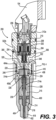
- FIGS. 3 thru 6 a fuel injector assembly 200 according to an embodiment of the present disclosure that may be used in the engine 100 just described will now be discussed in general terms concerning its construction and operation.
- the fuel injector assembly 200 includes a fuel injector body 300 that defines a common rail inlet 302, and a nozzle 400 that includes an injection outlet 402.
- a solenoid actuator 202 may be an assembly
- Stator assembly 206 includes a pole piece 208 and a stop pin 210 that are flush at an air gap plane 212 (only shown in FIG. 6 ).
- the stator assembly 206 may be substantially free of empty space between pole piece 208 and a centerline (may be the same as the longitudinal axis 306 of the fuel injector body 300, but not necessarily so).
- the stop pin 210 may be surrounded by, but radially spaced apart from, the pole piece 208, such as by a plastic filler material that may also serve to magnetically isolate the stop pin 210 from the pole piece 208.
- the solenoid actuator 202 is operably coupled to a check valve member 214 that includes a closing hydraulic surface 213 exposed to fluid pressure in a pressurized fuel chamber 215 that is disposed in the nozzle 400.
- the check valve member 214 is movable between a closed position (as shown) blocking the injection outlet 402, and an open position fluidly connecting the common rail inlet 302 to the injection outlet 402.
- the check valve member 214 also includes an opening hydraulic surface 216 that is exposed to fluid pressure in the common rail inlet 302, which corresponds to pressure in a common rail (not shown).
- a control valve member 218 may be provide (e.g. a ball) that is unattached to, but trapped between, a push pin 220 and a seat 222 of a valve plate 224.
- Control valve member 218 is movable between a closed position (as shown) in contact with seat 222, and an open position out of contact with seat 222 to fluidly connect the pressurized fuel chamber 215 to the drain outlet 304.
- the push pin 220 interacts at one end with armature 204 and at its opposite end with control valve member 218 to facilitate movement of control valve member 218 between its closed and open positions responsive to deenergizing and energizing the solenoid actuator 202, respectively.
- the pressurized fuel chamber 215 is shown partially defined by a sleeve 226 and an orifice piece 228.
- a biasing spring 230 may be operably positioned to simultaneously bias the sleeve 226 into contact with the orifice piece 228, and bias the check valve member 214 toward its downward closed position, as shown.
- Other springs 230a, 230b may be provided to bias the push pin 220 into contact with the seat 222, and to bias the armature 204 toward contact with the push pin 220 respectively.
- the common rail inlet 302 is fluidly connected (fluid communication) to the drain outlet 304 through orifices 232 of the orifice piece 228 (see FIG. 4 ).
- These orifices may assist in more abruptly ending injection events by fluidly connecting the pressurized fuel chamber 215 to the high pressure in common rail inlet 302 at the end of an injection event. That is to say, these orifices 232 may be sized to influence the rate at which the needle/check valve member 214 lifts from its closed position to its open position by influencing the rate at which fuel escapes to drain outlet 304 past control valve member 218.
- the fuel injector assembly 200 may comprise a fuel injector component (e.g. a nozzle 400, a sleeve 226) that defines a pressurized fuel chamber 215, and a check valve assembly 214a that is in fluid communication with the pressurized fuel chamber 215.
- This check valve assembly 214 may be disposed in the nozzle 400 or sleeve 226, etc.
- a fuel injector body 300 may be provided that includes an at least partially annular configuration defining a longitudinal axis 306 (may be a centerline), a circumferential direction 308, and a radial direction 310.
- a first end 312 may be disposed along the longitudinal axis, as well as a second end 312a (see FIG. 3 ).
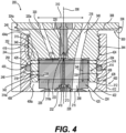
- the fuel injector body 300 may further define a first counterbore 314, and a first cavity 314a (see FIG. 4 ) that extends longitudinally from the first end 312 toward the second end 312a, terminating short thereof.
- a nozzle 400 may be provided that defines a first longitudinal end 404 (see FIG. 3 ), and a second longitudinal end 404a (see FIG. 4a) that is disposed longitudinally adjacent to the first end 312 of the fuel injector body 300.
- the nozzle may define a second counterbore 406 with a second cavity 406a that extends longitudinally from the second longitudinal end 404a toward the first longitudinal end 404.
- the first end 312 of the fuel injector body 300 may be disposed in the second counterbore 406, and the second cavity 406a of the nozzle 400, forming an interface region 244 with the nozzle 400, and a seam 246 between the fuel injector body 300 and the nozzle 400.
- the fuel injector assembly 200 may further define a radial seal receiving groove 248 disposed longitudinally along the seam 246. This groove 248 may be formed on either the fuel injector body 300 or the nozzle 400.
- a seal 250 would typically be disposed in the radial seal receiving groove 248.
- the second cavity 406a of the nozzle 400 includes a radially inner circumferential surface 408 that defines the radial seal receiving groove 248.
- the fuel injector assembly 200 may define a minimum seal receiving groove inner diameter 410, a minimum first cavity diameter 316 that is defined by a first cavity circumferential surface 315, and a ratio of the minimum seal receiving groove inner diameter 410 to the minimum first cavity diameter may range from 1.1 to 4.0.
- the fuel injector body 300 may define a radial wall thickness 318 that is disposed radially between the radial seal receiving groove 248, and the first cavity circumferential surface 315 that ranges from 5.0 mm to 22.0 mm.
- the nozzle 400 may define a radially outer circumferential surface 412, and a minimum radial wall thickness 414 measured radially from the radially outer circumferential surface 412 to the radial seal receiving groove 248 that ranges from 7.0 mm to 22.0 mm.
- this region includes meshing threads 252. It is contemplated that other forms of interfacing or attaching the nozzle to the fuel injector body are possible, as well as other ratios and dimensional ranges in other embodiments of the present disclosure.
- the fuel injector assembly may further comprise a valve plate 224 that is disposed in the first cavity 314a, an orifice piece 228 that is disposed in the nozzle 400 contacting the valve plate 224, and a control valve 218 disposed in the fuel injector body 300 above the valve plate 224 and the orifice piece 228.
- a valve plate 224 that is disposed in the first cavity 314a
- an orifice piece 228 that is disposed in the nozzle 400 contacting the valve plate 224
- a control valve 218 disposed in the fuel injector body 300 above the valve plate 224 and the orifice piece 228.
- the fuel injector body 300 defines a drain passage 320 that is in communication with the first cavity 314a of the fuel injector body 300, as well as a low pressure drain cavity 322.
- the fuel injector body 300 further defines a radially outer circumferential surface 324, and the low pressure drain cavity 322 takes the form of a circumferential groove 322a disposed on the radially outer circumferential surface 324 axially between an upper seal 326 (see FIG. 5 ), and a lower seal 328.
- the first cavity 314a may be defined by a bottom surface 330 (e.g. a planar annular surface) and the drain passage 320 is a bore (e.g. drilled using a convention drill or Electric Discharge Machining, etc.) that extends from the bottom surface 330 to the circumferential groove 322a along a direction that forms an oblique angle 332 with the longitudinal axis 306 in a plane containing the longitudinal axis 306, and the radial direction 310 (e.g. the sectioned plane of FIG. 6 ).
- a bore e.g. drilled using a convention drill or Electric Discharge Machining, etc.
- components such as a fuel injector body and/or a nozzle that may be supplied as a replacement part to repair, refurbish, or retrofit a fuel injector assembly will now be discussed with reference to FIGS. 3 and 4 .
- Such a fuel injector body 300 shown in FIG. 4 may include an external interface portion 334 including a sealing surface 335 that is disposed axially between the first end 312, and a shoulder 336. More particularly, an externally threaded portion 344 may be disposed axially between the sealing surface 335, and the shoulder 336.
- the first cavity 314a defines a bottom surface 330, and a peripheral surface 338 defining a first cavity diameter 316a.
- the sealing surface 335 may define a sealing surface diameter 340, and a ratio of the sealing surface diameter 340 to the first cavity diameter 316 may range from 0.3 to 4.4 in some embodiments.
- the body may define a radial thickness 342 from the sealing surface 335 to the peripheral surface 338 ranging from 5.0 mm to 22.0 mm. This may not be the case in other embodiments of the present disclosure.
- the first cavity 314a may define a first cavity axial depth 346 from the bottom surface 330 to the first end 312, and a ratio of the sealing surface diameter 340 to the first cavity axial depth 346 ranges from 0.2 to 4.4.
- the first cavity axial depth 346 may range from 5.0 mm to 30.0 mm.
- Other configurations, dimensions, and ratios are possible in other embodiments of the present disclosure.
- a radially outer surface 324a is disposed radially outwardly from the shoulder 336 that defines a low pressure drain groove 322b (see FIG. 6 ).
- a leak passage 320a extends from the bottom surface 330 to the low pressure drain groove 322b, which in turn is in communication with the drain outlet 304 (see FIG. 5 ). High pressure may thus be relieved when a problem occurs, minimizing the risk of further damage to the components of the fuel injector assembly.
- a replacement nozzle 400 may be an assembly as shown
- the nozzle 400 may include a first longitudinal end 404, and a second longitudinal and 404a.
- An attachment portion 416 may be disposed at the second longitudinal end 404a, while a tip portion 418 with the injection outlet 402 may be disposed at the first longitudinal end 404
- the attachment portion 416 may include a fuel injector body receiving cavity 420 defining an inner circumferential surface 422 (may include any surface of revolution including conical, cylindrical, etc.) that includes internal threads 424 extending from the second longitudinal end 404a, and that defines a seal receiving groove 426 that is disposed axially below the internal threads 424.
- a fuel injector body receiving cavity 420 defining an inner circumferential surface 422 (may include any surface of revolution including conical, cylindrical, etc.) that includes internal threads 424 extending from the second longitudinal end 404a, and that defines a seal receiving groove 426 that is disposed axially below the internal threads 424.
- the attachment portion 416 may include a maximum radial wall thickness 428 (e.g. slightly above or below the seal receiving groove 426) disposed circumferentially about the fuel injector body receiving cavity 420, and a minimum radial wall thickness 430 disposed circumferentially about the fuel injector body receiving cavity 420 (e.g. at the seal receiving groove 426).
- a ratio of the maximum radial wall thickness 428 to the minimum radial wall thickness 430 may range from 0.12 to 17.0 in some embodiments. In such a case, the maximum radial wall thickness 428 may range from 2.0 mm to 17.0 mm, while the minimum radial wall thickness 430 may range from 1.0 mm to 17.0 mm.
- the seal receiving groove 426 may be spaced away from the internal threads 424 a minimum axial distance 432 (see FIG. 6 ) that ranges from 2.0 mm to 25.0 mm.
- a minimum axial distance 432 (see FIG. 6 ) that ranges from 2.0 mm to 25.0 mm.
- Other configurations, dimensional ratios, and dimensions are possible in other embodiments of the present disclosure.
- the fuel injector body 300 of the fuel injector assembly 200 may be disposed in the second counterbore 406, and the second cavity 406a of the nozzle 400, forming an interface region 244 with the nozzle 400, and a seam 246 between the fuel injector body 300, and the nozzle 400.
- the fuel injector body may further define a supply passage 348 in communication with the pressurized fuel chamber 215 and the common rail inlet 302 for supplying the fuel.
- a leak passage 320a may extend from the first cavity 314a.
- the fuel injector body 300 defines a bottom surface 330 of the first cavity 314a, and the leak passage 320a may extend from the bottom surface 330 radially on one side of the longitudinal axis 306, while the supply passage 348 extends to the bottom surface 330 radially on the other side of the longitudinal axis 306 in a plane containing the radial direction 310, and the longitudinal axis 306 (e.g. in the sectioned plane of FIG. 4 ).
- the fuel injector body 300 may include an outer peripheral surface 339 that that is disposed radially outwardly from the nozzle 400.
- the outer peripheral surface 339 may define a low pressure drain groove 322b that is in communication with the leak passage 320a.
- a valve plate 224 may be disposed in the first cavity 314a, including an abutting sealing surface 254 facing the bottom surface 330 of the first cavity 314a. This abutting sealing surface 254 may define a reservoir 256 that is in communication with the leak passage 320a, as well as a thru-passage 258 (see FIG. 4 ) that fluidly connects the supply passage 348 to the pressurized fuel chamber 215.
- the leak passage, the thru-passage, and the supply passage may all extend along directions that are oblique to the longitudinal axis and radial direction. Also, the supply passage and thru-passage may be oblique to each other (i.e. not straight with respect to each other). Other configurations are possible in other embodiments of the present disclosure.
- the leak passage 320a may take the form of a straight bore (e.g. cylindrical) that is machined or otherwise formed into the fuel injector body 300.
- the leak passage 320a may define a passage diameter 350
- the first cavity 314a may define a first cavity diameter 316a (see FIG. 4 ).
- a ratio of the first cavity diameter 316a to the passage diameter 350 may range from 2.0 to 10.0 in certain embodiments of the present disclosure.
- the leak passage diameter may range from 1.0 mm to 5.0 mm. Other ranges are possible in other embodiments of the present disclosure.
- the fuel injector assembly 200 may further define a radial seal receiving groove 248 that is disposed longitudinally along the seam 246 (see FIG. 4 ) with a seal 250 that is disposed in the radial seal receiving groove 248.
- the radial seal receiving groove may be disposed axially below the bottom surface 330 of the first cavity 314a, but not necessarily so.
- the second cavity 406a of the nozzle 400 includes a radially inner circumferential surface 422a that defines the radial seal receiving groove 248. This may not be the case for other embodiments of the present disclosure.
- the fuel injector body 300 may include an external interface portion 334 including a sealing surface 335 that is disposed axially between the first end 312 and a shoulder 336.
- the first cavity 314a defines a bottom surface 330 and a peripheral surface 338, while a leak passage 320a extends from the bottom surface 330 that is in communication with the first cavity 314a.
- the leak passage 320a extends along a direction that is oblique to the radial direction 310, and the longitudinal axis 306.
- the direction along which the leak passage extends is in the same plane as the radial direction and the longitudinal axis (e.g. the sectioned plane of FIG. 6 ). This may not be the case in other embodiments of the present disclosure.
- the fuel injector body 300 may further define a supply passage 348 that extends to the first cavity 314a as seen in FIG. 4 , but not necessarily so.
- the fuel injector body 300 may include a stepped configuration including a side circumferential surface 324b (e.g. any surface of revolution including a conical surface, a cylindrical surface) that is spaced radially and axially away from the shoulder 336, and the external interface portion 334.
- the side circumferential surface 324b defines a low pressure drain groove 322b, and the leak passage 320a extends to the low pressure drain groove 322. More specifically, the low pressure drain groove 322b defines a corner 352, and the leak passage 320a may extend to the corner 352 as shown, or some other portion of the groove such as its bottom surface, its side surface, etc.
- the fuel injector body 300 has an external male attachment portion 334a including a sealing surface 335 that is disposed axially between the first end 312, and a shoulder 336.
- the peripheral surface 338 defines a cavity diameter 316a, and the sealing surface defines a sealing surface diameter 340, and a ratio of the sealing surface diameter 340 to the cavity diameter 316 may range from 0.3 to 4.4 in some embodiments of the present disclosure.
- the external male attachment portion 334a includes external threads 344a that are disposed axially between the sealing surface 335 and the shoulder 336.
- a wall 354 is disposed circumferentially about the first cavity 314a, defining a minimum radial wall thickness 318a, and a maximum axial wall height 319 (see FIG. 5 ).
- the minimum radial wall thickness 318a may range from 1.0 mm to 22.0 mm
- the maximum axial wall height 319 may range from 5.0 mm to 30.0 mm.
- the fuel injector body and the nozzle may be made from similar materials such as steel.
- a nozzle, a fuel injector body and/or a fuel injector assembly may be provided, sold, manufactured, and bought etc. to refurbish, retrofit or remanufacture existing fuel injector assemblies in the field.
- a fuel injector assembly may also be provided, sold, manufactured, and bought, etc. to provide a new fuel injector that includes such a nozzle, a fuel injector body, or a fuel injector assembly.
- the fuel injector body, the nozzle, or fuel injector assembly may be new or refurbished, remanufactured, etc.
- the present disclosure finds general applicability to fuel injectors for common rail fueling applications.
- the present disclosure finds specific application to common rail fuel injectors used in compression ignition engines.
- other applications in other types of engines and other types of fuel injectors are contemplated to be within the scope of the present disclosure.
- fuel injector assembly 200 In operation between injection events, fuel injector assembly 200 will be in a rest configuration, as shown.
- solenoid actuator 202 When in the rest configuration, solenoid actuator 202 is de-energized, armature 204 is in contact with push pin 220, and control valve member 218 is in its closed position in contact with the seat 222.
- the check valve member 214 In addition, in the rest configuration the check valve member 214 is in its downward closed position blocking the nozzle injection outlet 402.
- the pressure in the pressurized fuel chamber 215 is high such that rail pressure may be acting on both the closing hydraulic surface 213 and the opening hydraulic surface 216.
- An injection event is initiated by energizing solenoid actuator 202.
- the pole piece 208 magnetically attracts the armature 204.
- push pin 220 is lifted to allow the high pressure in pressurized fuel chamber 215 to push control valve member 218 off of the seat 222 to fluidly connect the pressurized fuel chamber 215 to the low pressure of drain outlet 304.
- the motion of armature 204 will stop when sit contacts the stop pin 210.
- pressure in pressurized fuel chamber 215 drops sufficiently, the high pressure acting on opening hydraulic surface 216 pushes check valve member 214 upward against the action of biasing spring 230 to commence an injection event.
- check valve member 214 When fuel injector is in the injection configuration, check valve member 214 is in its upward open position, control valve member 218 is in its open position out of contact with the seat 222, and push pin 220 is in contact with stop pin 210 and armature 204, with armature 204 being at a final air gap distance away from stator assembly 206.
- pressures in the nozzle and fuel injector body may be high.
- the embodiments discussed herein may help to prevent the leaking of fuel at the interface between the nozzle and the fuel injector body, and/or may help to provide pressure relief so that fuel injector components are not damaged if a problem occurs such as a stuck component.
- the pressure in the nozzle and high pressure passage in the body may be high, not just during the injection event.
- the ball which may take the form of a flattened geometry to form a seat as shown in the drawings
- the pressure on top of the check valve may be evacuated, inducing a pressure imbalance, allowing the check valve ball to lift, opening the tip to the check valve seat, allowing the injection event to occur.
Landscapes
- Engineering & Computer Science (AREA)
- Chemical & Material Sciences (AREA)
- Combustion & Propulsion (AREA)
- Mechanical Engineering (AREA)
- General Engineering & Computer Science (AREA)
- Manufacturing & Machinery (AREA)
- Physics & Mathematics (AREA)
- Fluid Mechanics (AREA)
- Fuel-Injection Apparatus (AREA)
Claims (5)
- Corps d'injecteur de carburant (300) pour une utilisation avec un injecteur de carburant, le corps d'injecteur de carburant (300) comprenant :un corps qui comporte une configuration au moins partiellement annulaire définissant un axe longitudinal (306), une direction circonférentielle (308) et une direction radiale (310) ;une première extrémité (312) qui est disposée axialement le long de l'axe longitudinal (306), et une seconde extrémité (312a) qui est disposée axialement le long de l'axe longitudinal (306) ;un premier contre-alésage (314) et une première cavité qui s'étend à partir de la première extrémité (312) vers la seconde extrémité (312a) ; etune partie d'interface extérieure (334) comportant une surface d'étanchéité (335) qui est disposée axialement entre la première extrémité (312) et un épaulement (336) ;dans lequel la première cavité (314a) définit une surface inférieure (330) et une surface périphérique (338), la surface périphérique (338) définissant un diamètre de première cavité (316a), et la surface d'étanchéité (335) définissant un diamètre de surface d'étanchéité (340), et un rapport entre le diamètre de surface d'étanchéité (340) et le diamètre de première cavité (316a) est compris dans une plage allant de 0,3 à 4,4 ;caractérisé en ce que le corps comporte en outre une surface radialement externe (324a) qui est disposée radialement vers l'extérieur à partir de l'épaulement (336), la surface radialement externe (324a) définissant une rainure d'évacuation basse pression (322b), et le corps définissant un passage de fuite (320a) s'étendant à partir de la surface inférieure (330) vers la rainure d'évacuation basse pression (322b).
- Corps d'injecteur de carburant (300) selon la revendication 1, dans lequel le corps définit une épaisseur radiale (342) à partir de la surface d'étanchéité (335) vers la surface périphérique (338) allant de 5,0 mm à 22,0 mm.
- Corps d'injecteur de carburant (300) selon la revendication 1, dans lequel la première cavité (314a) définit une profondeur axiale de première cavité (346) à partir de la surface inférieure (330) vers la première extrémité (312), et un rapport entre le diamètre de surface d'étanchéité (340) et la profondeur axiale de première cavité (346) est compris dans une plage allant de 0,2 à 4,4.
- Corps d'injecteur de carburant (300) selon la revendication 3, dans lequel la profondeur axiale de première cavité (346) est comprise dans une plage allant de 5,0 mm à 30,0 mm.
- Corps d'injecteur de carburant (300) selon la revendication 1, dans lequel la partie d'interface extérieure (334) comporte une partie filetée extérieurement (344) qui est disposée axialement entre la surface d'étanchéité (335) et l'épaulement (336).
Applications Claiming Priority (1)
| Application Number | Priority Date | Filing Date | Title |
|---|---|---|---|
| US17/024,891 US11174827B1 (en) | 2020-09-18 | 2020-09-18 | Fuel injector with internal radial seal with thin wall counterbore |
Publications (2)
| Publication Number | Publication Date |
|---|---|
| EP3971410A1 EP3971410A1 (fr) | 2022-03-23 |
| EP3971410B1 true EP3971410B1 (fr) | 2024-09-25 |
Family
ID=77520521
Family Applications (1)
| Application Number | Title | Priority Date | Filing Date |
|---|---|---|---|
| EP21193411.2A Active EP3971410B1 (fr) | 2020-09-18 | 2021-08-27 | Injecteur de carburant doté d'un joint d'étanchéité radial interne avec contre-alésage à paroi mince |
Country Status (3)
| Country | Link |
|---|---|
| US (1) | US11174827B1 (fr) |
| EP (1) | EP3971410B1 (fr) |
| CN (1) | CN114198231A (fr) |
Families Citing this family (3)
| Publication number | Priority date | Publication date | Assignee | Title |
|---|---|---|---|---|
| WO2021113320A1 (fr) * | 2019-12-02 | 2021-06-10 | Cummins Inc. | Écran de combustion de buse d'injecteur rainuré |
| US11591995B2 (en) * | 2020-09-15 | 2023-02-28 | Caterpillar Inc. | Fuel injector having valve seat orifice plate with valve seat and drain and re-pressurization orifices |
| US11840993B1 (en) * | 2023-02-01 | 2023-12-12 | Caterpillar Inc. | Fuel-actuated fuel injector having cooling fuel circuit and method |
Citations (1)
| Publication number | Priority date | Publication date | Assignee | Title |
|---|---|---|---|---|
| DE102009046582A1 (de) * | 2009-11-10 | 2011-05-12 | Robert Bosch Gmbh | Verfahren zum Herstellen eines Kraftstoffeinspritzventils und Kraftstoffeinspritzventil |
Family Cites Families (20)
| Publication number | Priority date | Publication date | Assignee | Title |
|---|---|---|---|---|
| US3945353A (en) * | 1974-11-29 | 1976-03-23 | Allis-Chalmers Corporation | Two phase nozzle cooling system |
| US4230273A (en) | 1978-02-07 | 1980-10-28 | The Bendix Corporation | Fuel injection valve and single point system |
| US5241935A (en) * | 1988-02-03 | 1993-09-07 | Servojet Electronic Systems, Ltd. | Accumulator fuel injection system |
| US5330100A (en) * | 1992-01-27 | 1994-07-19 | Igor Malinowski | Ultrasonic fuel injector |
| DK174240B1 (da) | 1994-03-08 | 2002-10-14 | Man B & W Diesel As | Brændselsventil og højtryksgasmotor med en sådan ventil |
| US5540388A (en) * | 1994-03-25 | 1996-07-30 | Kabushiki Kaisha Keihinseiki Seisakusho | Solenoid type fuel injection valve |
| JPH0874699A (ja) * | 1994-09-09 | 1996-03-19 | Zexel Corp | 燃料噴射弁 |
| US5823429A (en) * | 1996-07-12 | 1998-10-20 | Servojet Products International | Hybrid hydraulic electronic unit injector |
| US5852997A (en) * | 1997-05-20 | 1998-12-29 | Stanadyne Automotive Corp. | Common rail injector |
| JP2001123907A (ja) * | 1999-10-26 | 2001-05-08 | Aisan Ind Co Ltd | 燃料噴射弁 |
| DE10051549A1 (de) * | 2000-10-18 | 2002-04-25 | Bosch Gmbh Robert | Magnetventil zur Steuerung eines Einspritzventils einer Brennkraftmaschine |
| JP3928362B2 (ja) | 2001-02-14 | 2007-06-13 | 株式会社デンソー | 流体移送装置のシール面圧向上構造 |
| DE10358266B4 (de) * | 2003-12-11 | 2008-06-05 | L'orange Gmbh | Kraftstoff-Einspritzsystem für Brennkraftmaschinen |
| DE102004053421A1 (de) | 2004-11-05 | 2006-05-11 | Robert Bosch Gmbh | Kraftstoffeinspritzvorrichtung |
| EP1783357B1 (fr) | 2005-11-02 | 2008-06-04 | Delphi Technologies, Inc. | Structure de connexion pour l'alimentation haute pression en carburant pour un injecteur |
| JP5375762B2 (ja) | 2010-07-14 | 2013-12-25 | 株式会社デンソー | 燃料噴射装置 |
| DE102013003104A1 (de) | 2013-02-25 | 2014-08-28 | L'orange Gmbh | Krafftstoffinjektor |
| US10077748B2 (en) | 2014-12-23 | 2018-09-18 | Cummins Inc. | Fuel injector for common rail |
| US20170241550A1 (en) | 2016-02-18 | 2017-08-24 | Caterpillar Inc. | Seal for fuel injector system |
| DE112017007931T5 (de) | 2017-10-20 | 2020-06-04 | Cummins Inc. | Kraftstoffinjektor mit flexiblem bauteil |
-
2020
- 2020-09-18 US US17/024,891 patent/US11174827B1/en active Active
-
2021
- 2021-08-27 EP EP21193411.2A patent/EP3971410B1/fr active Active
- 2021-09-17 CN CN202111092850.5A patent/CN114198231A/zh active Pending
Patent Citations (1)
| Publication number | Priority date | Publication date | Assignee | Title |
|---|---|---|---|---|
| DE102009046582A1 (de) * | 2009-11-10 | 2011-05-12 | Robert Bosch Gmbh | Verfahren zum Herstellen eines Kraftstoffeinspritzventils und Kraftstoffeinspritzventil |
Also Published As
| Publication number | Publication date |
|---|---|
| EP3971410A1 (fr) | 2022-03-23 |
| US11174827B1 (en) | 2021-11-16 |
| CN114198231A (zh) | 2022-03-18 |
Similar Documents
| Publication | Publication Date | Title |
|---|---|---|
| EP3971410A1 (fr) | Injecteur de carburant doté d'un joint d'étanchéité radial interne avec contre-alésage à paroi mince | |
| US5082180A (en) | Electromagnetic valve and unit fuel injector with electromagnetic valve | |
| US10767611B2 (en) | Fuel injector | |
| US5884848A (en) | Fuel injector with piezoelectric and hydraulically actuated needle valve | |
| EP3971409A1 (fr) | Injecteur de carburant avec passage de fuite interne vers le drain de l'injecteur | |
| KR100427569B1 (ko) | 내연기관용연료인젝터 | |
| EP3449117B1 (fr) | Pompe diesel haute pression | |
| AU2015299011A1 (en) | Injecting apparatus and method of using an injecting apparatus | |
| US20060081722A1 (en) | Gaseous fuel injector for internal combustion engine | |
| EP0903490B1 (fr) | Injecteur | |
| US20160230728A1 (en) | Plunger And Fluid-Line System | |
| KR20210022578A (ko) | 인젝터 장치 | |
| US6209524B1 (en) | Fuel-injection apparatus | |
| US20070251499A1 (en) | High-Pressure Pump for a Fuel Injection System of an Internal Combustion Engine | |
| JP5293226B2 (ja) | 電磁弁および電磁弁を用いた燃料噴射装置 | |
| EP0630443B1 (fr) | Pompe a carburant | |
| US20120180761A1 (en) | High-pressure unit fuel injector | |
| RU2526002C2 (ru) | Электроуправляемая форсунка | |
| US20120181351A1 (en) | Nozzle and needle of a high-pressure unit fuel injector | |
| WO2025176441A1 (fr) | Pompe à carburant et agencement d'étanchéité associé | |
| WO2025176442A1 (fr) | Pompe à carburant et agencement de piston associé | |
| KR102659828B1 (ko) | 연료 펌프 조립체 | |
| WO2025176440A1 (fr) | Pompe à carburant et agencement d'étanchéité associé | |
| JP2016048039A (ja) | 燃料噴射弁 |
Legal Events
| Date | Code | Title | Description |
|---|---|---|---|
| PUAI | Public reference made under article 153(3) epc to a published international application that has entered the european phase |
Free format text: ORIGINAL CODE: 0009012 |
|
| STAA | Information on the status of an ep patent application or granted ep patent |
Free format text: STATUS: THE APPLICATION HAS BEEN PUBLISHED |
|
| AK | Designated contracting states |
Kind code of ref document: A1 Designated state(s): AL AT BE BG CH CY CZ DE DK EE ES FI FR GB GR HR HU IE IS IT LI LT LU LV MC MK MT NL NO PL PT RO RS SE SI SK SM TR |
|
| STAA | Information on the status of an ep patent application or granted ep patent |
Free format text: STATUS: REQUEST FOR EXAMINATION WAS MADE |
|
| 17P | Request for examination filed |
Effective date: 20220921 |
|
| RBV | Designated contracting states (corrected) |
Designated state(s): AL AT BE BG CH CY CZ DE DK EE ES FI FR GB GR HR HU IE IS IT LI LT LU LV MC MK MT NL NO PL PT RO RS SE SI SK SM TR |
|
| GRAP | Despatch of communication of intention to grant a patent |
Free format text: ORIGINAL CODE: EPIDOSNIGR1 |
|
| STAA | Information on the status of an ep patent application or granted ep patent |
Free format text: STATUS: GRANT OF PATENT IS INTENDED |
|
| INTG | Intention to grant announced |
Effective date: 20231204 |
|
| P01 | Opt-out of the competence of the unified patent court (upc) registered |
Effective date: 20240409 |
|
| GRAS | Grant fee paid |
Free format text: ORIGINAL CODE: EPIDOSNIGR3 |
|
| GRAA | (expected) grant |
Free format text: ORIGINAL CODE: 0009210 |
|
| STAA | Information on the status of an ep patent application or granted ep patent |
Free format text: STATUS: THE PATENT HAS BEEN GRANTED |
|
| AK | Designated contracting states |
Kind code of ref document: B1 Designated state(s): AL AT BE BG CH CY CZ DE DK EE ES FI FR GB GR HR HU IE IS IT LI LT LU LV MC MK MT NL NO PL PT RO RS SE SI SK SM TR |
|
| REG | Reference to a national code |
Ref country code: GB Ref legal event code: FG4D |
|
| REG | Reference to a national code |
Ref country code: CH Ref legal event code: EP |
|
| REG | Reference to a national code |
Ref country code: DE Ref legal event code: R096 Ref document number: 602021019222 Country of ref document: DE |
|
| REG | Reference to a national code |
Ref country code: IE Ref legal event code: FG4D |
|
| REG | Reference to a national code |
Ref country code: LT Ref legal event code: MG9D |
|
| PG25 | Lapsed in a contracting state [announced via postgrant information from national office to epo] |
Ref country code: NO Free format text: LAPSE BECAUSE OF FAILURE TO SUBMIT A TRANSLATION OF THE DESCRIPTION OR TO PAY THE FEE WITHIN THE PRESCRIBED TIME-LIMIT Effective date: 20241225 |
|
| PG25 | Lapsed in a contracting state [announced via postgrant information from national office to epo] |
Ref country code: GR Free format text: LAPSE BECAUSE OF FAILURE TO SUBMIT A TRANSLATION OF THE DESCRIPTION OR TO PAY THE FEE WITHIN THE PRESCRIBED TIME-LIMIT Effective date: 20241226 Ref country code: FI Free format text: LAPSE BECAUSE OF FAILURE TO SUBMIT A TRANSLATION OF THE DESCRIPTION OR TO PAY THE FEE WITHIN THE PRESCRIBED TIME-LIMIT Effective date: 20240925 |
|
| PG25 | Lapsed in a contracting state [announced via postgrant information from national office to epo] |
Ref country code: BG Free format text: LAPSE BECAUSE OF FAILURE TO SUBMIT A TRANSLATION OF THE DESCRIPTION OR TO PAY THE FEE WITHIN THE PRESCRIBED TIME-LIMIT Effective date: 20240925 |
|
| PG25 | Lapsed in a contracting state [announced via postgrant information from national office to epo] |
Ref country code: LV Free format text: LAPSE BECAUSE OF FAILURE TO SUBMIT A TRANSLATION OF THE DESCRIPTION OR TO PAY THE FEE WITHIN THE PRESCRIBED TIME-LIMIT Effective date: 20240925 |
|
| PG25 | Lapsed in a contracting state [announced via postgrant information from national office to epo] |
Ref country code: RS Free format text: LAPSE BECAUSE OF FAILURE TO SUBMIT A TRANSLATION OF THE DESCRIPTION OR TO PAY THE FEE WITHIN THE PRESCRIBED TIME-LIMIT Effective date: 20241225 |
|
| REG | Reference to a national code |
Ref country code: NL Ref legal event code: MP Effective date: 20240925 |
|
| PG25 | Lapsed in a contracting state [announced via postgrant information from national office to epo] |
Ref country code: RS Free format text: LAPSE BECAUSE OF FAILURE TO SUBMIT A TRANSLATION OF THE DESCRIPTION OR TO PAY THE FEE WITHIN THE PRESCRIBED TIME-LIMIT Effective date: 20241225 Ref country code: NO Free format text: LAPSE BECAUSE OF FAILURE TO SUBMIT A TRANSLATION OF THE DESCRIPTION OR TO PAY THE FEE WITHIN THE PRESCRIBED TIME-LIMIT Effective date: 20241225 Ref country code: LV Free format text: LAPSE BECAUSE OF FAILURE TO SUBMIT A TRANSLATION OF THE DESCRIPTION OR TO PAY THE FEE WITHIN THE PRESCRIBED TIME-LIMIT Effective date: 20240925 Ref country code: GR Free format text: LAPSE BECAUSE OF FAILURE TO SUBMIT A TRANSLATION OF THE DESCRIPTION OR TO PAY THE FEE WITHIN THE PRESCRIBED TIME-LIMIT Effective date: 20241226 Ref country code: FI Free format text: LAPSE BECAUSE OF FAILURE TO SUBMIT A TRANSLATION OF THE DESCRIPTION OR TO PAY THE FEE WITHIN THE PRESCRIBED TIME-LIMIT Effective date: 20240925 Ref country code: BG Free format text: LAPSE BECAUSE OF FAILURE TO SUBMIT A TRANSLATION OF THE DESCRIPTION OR TO PAY THE FEE WITHIN THE PRESCRIBED TIME-LIMIT Effective date: 20240925 |
|
| REG | Reference to a national code |
Ref country code: AT Ref legal event code: MK05 Ref document number: 1726815 Country of ref document: AT Kind code of ref document: T Effective date: 20240925 |
|
| PG25 | Lapsed in a contracting state [announced via postgrant information from national office to epo] |
Ref country code: NL Free format text: LAPSE BECAUSE OF FAILURE TO SUBMIT A TRANSLATION OF THE DESCRIPTION OR TO PAY THE FEE WITHIN THE PRESCRIBED TIME-LIMIT Effective date: 20240925 |
|
| PG25 | Lapsed in a contracting state [announced via postgrant information from national office to epo] |
Ref country code: PT Free format text: LAPSE BECAUSE OF FAILURE TO SUBMIT A TRANSLATION OF THE DESCRIPTION OR TO PAY THE FEE WITHIN THE PRESCRIBED TIME-LIMIT Effective date: 20250127 Ref country code: IS Free format text: LAPSE BECAUSE OF FAILURE TO SUBMIT A TRANSLATION OF THE DESCRIPTION OR TO PAY THE FEE WITHIN THE PRESCRIBED TIME-LIMIT Effective date: 20250125 |
|
| PG25 | Lapsed in a contracting state [announced via postgrant information from national office to epo] |
Ref country code: RO Free format text: LAPSE BECAUSE OF FAILURE TO SUBMIT A TRANSLATION OF THE DESCRIPTION OR TO PAY THE FEE WITHIN THE PRESCRIBED TIME-LIMIT Effective date: 20240925 Ref country code: SM Free format text: LAPSE BECAUSE OF FAILURE TO SUBMIT A TRANSLATION OF THE DESCRIPTION OR TO PAY THE FEE WITHIN THE PRESCRIBED TIME-LIMIT Effective date: 20240925 |
|
| PG25 | Lapsed in a contracting state [announced via postgrant information from national office to epo] |
Ref country code: ES Free format text: LAPSE BECAUSE OF FAILURE TO SUBMIT A TRANSLATION OF THE DESCRIPTION OR TO PAY THE FEE WITHIN THE PRESCRIBED TIME-LIMIT Effective date: 20240925 |
|
| PG25 | Lapsed in a contracting state [announced via postgrant information from national office to epo] |
Ref country code: AT Free format text: LAPSE BECAUSE OF FAILURE TO SUBMIT A TRANSLATION OF THE DESCRIPTION OR TO PAY THE FEE WITHIN THE PRESCRIBED TIME-LIMIT Effective date: 20240925 Ref country code: EE Free format text: LAPSE BECAUSE OF FAILURE TO SUBMIT A TRANSLATION OF THE DESCRIPTION OR TO PAY THE FEE WITHIN THE PRESCRIBED TIME-LIMIT Effective date: 20240925 |
|
| PG25 | Lapsed in a contracting state [announced via postgrant information from national office to epo] |
Ref country code: CZ Free format text: LAPSE BECAUSE OF FAILURE TO SUBMIT A TRANSLATION OF THE DESCRIPTION OR TO PAY THE FEE WITHIN THE PRESCRIBED TIME-LIMIT Effective date: 20240925 Ref country code: PL Free format text: LAPSE BECAUSE OF FAILURE TO SUBMIT A TRANSLATION OF THE DESCRIPTION OR TO PAY THE FEE WITHIN THE PRESCRIBED TIME-LIMIT Effective date: 20240925 |
|
| PG25 | Lapsed in a contracting state [announced via postgrant information from national office to epo] |
Ref country code: IT Free format text: LAPSE BECAUSE OF FAILURE TO SUBMIT A TRANSLATION OF THE DESCRIPTION OR TO PAY THE FEE WITHIN THE PRESCRIBED TIME-LIMIT Effective date: 20240925 Ref country code: SK Free format text: LAPSE BECAUSE OF FAILURE TO SUBMIT A TRANSLATION OF THE DESCRIPTION OR TO PAY THE FEE WITHIN THE PRESCRIBED TIME-LIMIT Effective date: 20240925 |
|
| REG | Reference to a national code |
Ref country code: DE Ref legal event code: R097 Ref document number: 602021019222 Country of ref document: DE |
|
| PG25 | Lapsed in a contracting state [announced via postgrant information from national office to epo] |
Ref country code: DK Free format text: LAPSE BECAUSE OF FAILURE TO SUBMIT A TRANSLATION OF THE DESCRIPTION OR TO PAY THE FEE WITHIN THE PRESCRIBED TIME-LIMIT Effective date: 20240925 |
|
| PLBE | No opposition filed within time limit |
Free format text: ORIGINAL CODE: 0009261 |
|
| STAA | Information on the status of an ep patent application or granted ep patent |
Free format text: STATUS: NO OPPOSITION FILED WITHIN TIME LIMIT |
|
| 26N | No opposition filed |
Effective date: 20250626 |
|
| PG25 | Lapsed in a contracting state [announced via postgrant information from national office to epo] |
Ref country code: SE Free format text: LAPSE BECAUSE OF FAILURE TO SUBMIT A TRANSLATION OF THE DESCRIPTION OR TO PAY THE FEE WITHIN THE PRESCRIBED TIME-LIMIT Effective date: 20240925 |
|
| PGFP | Annual fee paid to national office [announced via postgrant information from national office to epo] |
Ref country code: DE Payment date: 20250724 Year of fee payment: 5 |
|
| PG25 | Lapsed in a contracting state [announced via postgrant information from national office to epo] |
Ref country code: HR Free format text: LAPSE BECAUSE OF FAILURE TO SUBMIT A TRANSLATION OF THE DESCRIPTION OR TO PAY THE FEE WITHIN THE PRESCRIBED TIME-LIMIT Effective date: 20240925 |
|
| REG | Reference to a national code |
Ref country code: CH Ref legal event code: H13 Free format text: ST27 STATUS EVENT CODE: U-0-0-H10-H13 (AS PROVIDED BY THE NATIONAL OFFICE) Effective date: 20260324 |
|
| PG25 | Lapsed in a contracting state [announced via postgrant information from national office to epo] |
Ref country code: MC Free format text: LAPSE BECAUSE OF FAILURE TO SUBMIT A TRANSLATION OF THE DESCRIPTION OR TO PAY THE FEE WITHIN THE PRESCRIBED TIME-LIMIT Effective date: 20240925 |
|
| PG25 | Lapsed in a contracting state [announced via postgrant information from national office to epo] |
Ref country code: LU Free format text: LAPSE BECAUSE OF NON-PAYMENT OF DUE FEES Effective date: 20250827 |
|
| PG25 | Lapsed in a contracting state [announced via postgrant information from national office to epo] |
Ref country code: CH Free format text: LAPSE BECAUSE OF NON-PAYMENT OF DUE FEES Effective date: 20250831 |
|
| GBPC | Gb: european patent ceased through non-payment of renewal fee |
Effective date: 20250827 |