EP3971538A1 - Dispositif de sécurité de gaz - Google Patents
Dispositif de sécurité de gaz Download PDFInfo
- Publication number
- EP3971538A1 EP3971538A1 EP20808824.5A EP20808824A EP3971538A1 EP 3971538 A1 EP3971538 A1 EP 3971538A1 EP 20808824 A EP20808824 A EP 20808824A EP 3971538 A1 EP3971538 A1 EP 3971538A1
- Authority
- EP
- European Patent Office
- Prior art keywords
- pressure
- gas
- flow rate
- pressure sensor
- sensor
- Prior art date
- Legal status (The legal status is an assumption and is not a legal conclusion. Google has not performed a legal analysis and makes no representation as to the accuracy of the status listed.)
- Granted
Links
Images


Classifications
-
- G—PHYSICS
- G05—CONTROLLING; REGULATING
- G05D—SYSTEMS FOR CONTROLLING OR REGULATING NON-ELECTRIC VARIABLES
- G05D7/00—Control of flow
- G05D7/06—Control of flow characterised by the use of electric means
- G05D7/0617—Control of flow characterised by the use of electric means specially adapted for fluid materials
- G05D7/0629—Control of flow characterised by the use of electric means specially adapted for fluid materials characterised by the type of regulator means
- G05D7/0635—Control of flow characterised by the use of electric means specially adapted for fluid materials characterised by the type of regulator means by action on throttling means
-
- G—PHYSICS
- G01—MEASURING; TESTING
- G01F—MEASURING VOLUME, VOLUME FLOW, MASS FLOW OR LIQUID LEVEL; METERING BY VOLUME
- G01F1/00—Measuring the volume flow or mass flow of fluid or fluent solid material wherein the fluid passes through a meter in a continuous flow
- G01F1/66—Measuring the volume flow or mass flow of fluid or fluent solid material wherein the fluid passes through a meter in a continuous flow by measuring frequency, phase shift or propagation time of electromagnetic or other waves, e.g. using ultrasonic flowmeters
-
- G—PHYSICS
- G01—MEASURING; TESTING
- G01F—MEASURING VOLUME, VOLUME FLOW, MASS FLOW OR LIQUID LEVEL; METERING BY VOLUME
- G01F1/00—Measuring the volume flow or mass flow of fluid or fluent solid material wherein the fluid passes through a meter in a continuous flow
- G01F1/72—Devices for measuring pulsing fluid flows
-
- G—PHYSICS
- G01—MEASURING; TESTING
- G01F—MEASURING VOLUME, VOLUME FLOW, MASS FLOW OR LIQUID LEVEL; METERING BY VOLUME
- G01F15/00—Details of, or accessories for, apparatus of groups G01F1/00 - G01F13/00 insofar as such details or appliances are not adapted to particular types of such apparatus
- G01F15/001—Means for regulating or setting the meter for a predetermined quantity
- G01F15/002—Means for regulating or setting the meter for a predetermined quantity for gases
-
- G—PHYSICS
- G01—MEASURING; TESTING
- G01F—MEASURING VOLUME, VOLUME FLOW, MASS FLOW OR LIQUID LEVEL; METERING BY VOLUME
- G01F15/00—Details of, or accessories for, apparatus of groups G01F1/00 - G01F13/00 insofar as such details or appliances are not adapted to particular types of such apparatus
- G01F15/005—Valves
-
- G—PHYSICS
- G01—MEASURING; TESTING
- G01L—MEASURING FORCE, STRESS, TORQUE, WORK, MECHANICAL POWER, MECHANICAL EFFICIENCY, OR FLUID PRESSURE
- G01L15/00—Devices or apparatus for measuring two or more fluid pressure values simultaneously
-
- G—PHYSICS
- G01—MEASURING; TESTING
- G01M—TESTING STATIC OR DYNAMIC BALANCE OF MACHINES OR STRUCTURES; TESTING OF STRUCTURES OR APPARATUS, NOT OTHERWISE PROVIDED FOR
- G01M3/00—Investigating fluid-tightness of structures
- G01M3/02—Investigating fluid-tightness of structures by using fluid or vacuum
- G01M3/26—Investigating fluid-tightness of structures by using fluid or vacuum by measuring rate of loss or gain of fluid, e.g. by pressure-responsive devices, by flow detectors
- G01M3/28—Investigating fluid-tightness of structures by using fluid or vacuum by measuring rate of loss or gain of fluid, e.g. by pressure-responsive devices, by flow detectors for pipes, cables or tubes; for pipe joints or seals; for valves ; for welds
- G01M3/2807—Investigating fluid-tightness of structures by using fluid or vacuum by measuring rate of loss or gain of fluid, e.g. by pressure-responsive devices, by flow detectors for pipes, cables or tubes; for pipe joints or seals; for valves ; for welds for pipes
- G01M3/2815—Investigating fluid-tightness of structures by using fluid or vacuum by measuring rate of loss or gain of fluid, e.g. by pressure-responsive devices, by flow detectors for pipes, cables or tubes; for pipe joints or seals; for valves ; for welds for pipes using pressure measurements
Definitions
- the present disclosure relates to a gas safety device that ensures safety in gas use by measuring a gas flow rate and shutting off a gas passage when an abnormal flow rate is measured.
- the gas safety device includes an ultrasonic flow rate measurement unit in which an ultrasonic sensor and a circuit board provided with an ultrasonic sensor drive circuit are integrated, and a pressure sensor that measures differential pressure between supply pressure and atmospheric pressure.
- the gas safety device further includes a control function of cutting off a flow path and stopping supply of gas, and a function of warning, when it is determined that the differential pressure between the supply pressure and the atmospheric pressure measured by the pressure sensor is abnormal.
- the pressure sensor incorporated in the gas safety device is a differential pressure measurement type that measures pressure of gas on the basis of atmospheric pressure, so that the pressure sensor has a through-hole through which the gas is introduced into the pressure sensor, and thus the gas may leak from the through-hole when temperature around the gas safety device excessively increases.
- examples of structure that does not require a through-hole include means for measuring change in gas supply pressure from a difference between measurement values of an absolute pressure sensor that measures atmospheric pressure and an absolute pressure sensor that measures gas pressure.
- a gas safety device includes a flow path for allowing gas to flow, a flow rate measurement unit for measuring a flow rate of the gas flowing through the flow path, a first pressure sensor disposed inside the flow path to measure absolute pressure of the gas, a second pressure sensor disposed outside the flow path to measure absolute pressure of atmospheric pressure, and a pressure value transition detector that detects a transition state of the absolute pressure measured by the first pressure sensor or the second pressure sensor.
- the gas safety device also includes a sensor drive controller that controls driving of the first pressure sensor or the second pressure sensor according to a transition value of the pressure value transition detector, and a gas pressure determination unit that calculates gas supply pressure from a difference between pressure values measured when the first pressure sensor and the second pressure sensor are both driven.
- the gas safety device further includes a shutoff valve that shuts off the flow path, and a control circuit that controls the flow rate measurement unit and causes the shutoff valve to shut off the flow path when determining anomaly from the flow rate measured by the flow rate measurement unit or the gas supply pressure calculated by the gas pressure determination unit.
- the present disclosure enables a gas safety device preventing gas from being ejected even at high temperature around the gas safety device to reduce power consumption even when two absolute pressure sensors are provided.
- FIGS. 1 and 2 a first exemplary embodiment will be described with reference to FIGS. 1 and 2 .
- FIG. 1 illustrates gas safety device 100 including: flow path 101 through which gas flows; shutoff valve 102 that shuts off flow path 101; flow rate measurement unit 103 that measures a flow rate of the gas flowing through flow path 101; and control circuit 104 that integrates the amount of gas usage using flow rate measurement data measured by flow rate measurement unit 103.
- Gas safety device 100 also includes gas-side absolute pressure sensor 105 being a first pressure sensor that measures absolute pressure of gas, atmosphere-side absolute pressure sensor 106 being a second pressure sensor that measures absolute pressure of atmosphere, electronic circuit 107 installed in gas atmosphere, and pressure value transition detector 108 that detects an absolute pressure transition state measured by gas-side absolute pressure sensor 105.
- Gas safety device 100 further includes sensor drive controller 109 that controls driving of atmosphere-side absolute pressure sensor 106 in accordance with a transition state of pressure values detected by pressure value transition detector 108, and gas pressure determination unit 110 that calculates gas supply pressure from a difference between two pressure values measured by gas-side absolute pressure sensor 105 and atmosphere-side absolute pressure sensor 106.
- Gas-side absolute pressure sensor 105 being the first pressure sensor is mounted as an electronic component on electronic circuit 107 installed in gas atmosphere inside flow path 101, and measures absolute pressure of the gas in flow path 101 using a signal from control circuit 104.
- Atmosphere-side absolute pressure sensor 106 being the second pressure sensor is mounted as an electronic component on control circuit 104 installed on an atmospheric side outside flow path 101, and measures atmospheric absolute pressure using a signal from control circuit 104.
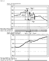
- FIG. 2 illustrates an example of change in absolute pressure on a gas side and in absolute pressure on the atmospheric side, and of measurement timing of gas-side absolute pressure sensor 105 being the first pressure sensor and atmosphere-side absolute pressure sensor 106 being the second pressure sensor, in an identical period.
- gas-side absolute pressure sensor 105 is always driven at predetermined intervals (e.g., two seconds to ten seconds) to perform measurement. That is, the predetermined intervals are intervals of the measurement timing of gas-side absolute pressure sensor 105.
- gas-side pressure value transition detector 108 detects that absolute pressure measured by gas-side absolute pressure sensor 105 has changed by a predetermined value (e.g., 2 kPa) or more
- sensor drive controller 109 drives atmosphere-side absolute pressure sensor 106 to measure pressure on the atmospheric side. Then, when the change in the absolute pressure measured by gas-side absolute pressure sensor 105 is less than the predetermined value, the measurement is stopped without driving atmosphere-side absolute pressure sensor 106.
- pressure change at each predetermined interval is less than 2 kPa until measurement timing Tn-1 of gas-side absolute pressure sensor 105, so that atmosphere-side absolute pressure sensor 106 is not driven.
- pressure difference ⁇ Pgn between absolute pressure Pgn-1 at measurement timing Tn-1 and absolute pressure Pgn at measurement timing Tn is 2 kPa or more, and atmosphere-side absolute pressure sensor 106 is driven to measure atmospheric absolute pressure Pan at measurement timing Tn.
- pressure difference ⁇ Pgn+1 between absolute pressure Pgn at measurement timing Tn using gas-side absolute pressure sensor 105 and absolute pressure Pgn+1 at measurement timing Tn+1 is less than 2 kPa, and thus driving of atmosphere-side absolute pressure sensor 106 is stopped.
- pressure change at each measurement timing of gas-side absolute pressure sensor 105 is less than 2 kPa, so that driving of atmosphere-side absolute pressure sensor 106 is stopped.
- gas pressure determination unit 110 can calculate gas supply pressure from a difference between the two measured pressure values.
- Control circuit 104 determines the flow rate measurement data measured by flow rate measurement unit 103, the gas supply pressure, and change in the gas supply pressure to determine whether there is an anomaly such as gas leakage. When determining that there is an anomaly, control circuit 104 causes shutoff valve 102 to shut off flow path 101 to stop gas supply.
- only gas-side absolute pressure sensor 105 being the first pressure sensor usually measures absolute pressure on the gas side, and driving and stopping of atmosphere-side absolute pressure sensor 106 being the second pressure sensor are controlled depending on whether a predetermined pressure change or more is detected.
- Such a configuration allows fluctuation of gas supply pressure to be detected using a difference between pressure values detected by the two absolute pressure sensors capable of reducing power consumption and measuring absolute pressure, so that a through-hole necessary for using a pressure sensor of a differential pressure measurement type is unnecessary, and thus a highly safe gas safety device can be fabricated.
- pressure value transition detector 108 uses a method for detecting a pressure difference between measurement timings using gas-side absolute pressure sensor 105, available methods include a method for detecting a pressure transition using a pressure difference between separated measurement timings, an average pressure difference of a plurality of measurement timings, a change pattern, or the like.
- flow rate measurement unit 103 is used for ultrasonic flow rate measurement in the present exemplary embodiment, an equivalent measurement can be performed.
- gas-side absolute pressure sensor 105 is mounted on electronic circuit 107 installed in the gas atmosphere inside flow path 101
- absolute pressure sensor 105 may be mounted anywhere inside flow path 101.
- atmosphere-side absolute pressure sensor 106 is mounted on control circuit 104 installed on the atmospheric side outside flow path 101
- a mounting place is not limited as long as atmospheric pressure can be measured.
- FIG. 3 the same components described in FIG. 1 are denoted by the same reference numerals, and duplicated description thereof is eliminated.
- Gas safety device 200 includes flow path 101, shutoff valve 102, flow rate measurement unit 103 that measures a flow rate of the gas flowing through flow path 101, and control circuit 204 that integrates the amount of gas usage using flow rate measurement data measured by flow rate measurement unit 103.
- Gas safety device 200 also includes gas-side absolute pressure sensor 105 being a first pressure sensor, atmosphere-side absolute pressure sensor 106 being a second pressure sensor, electronic circuit 107 installed in gas atmosphere, and sensor drive controller 209 that controls driving of gas-side absolute pressure sensor 105 and atmosphere-side absolute pressure sensor 106.
- Gas safety device 200 also includes a gas-side pressure value collector 201 that collects a pressure value measured by gas-side absolute pressure sensor 105 n times, and atmosphere-side pressure value collector 202 that collects a pressure value measured by atmosphere-side absolute pressure sensor 106 n times.
- Gas safety device 200 further includes gas-side previous value comparator 220 that compares a previous pressure value and a current pressure value that are obtained by gas-side pressure value collector 201, atmosphere-side previous value comparator 221 that compares a previous pressure value and a current pressure value that are obtained by atmosphere-side pressure value collector 202, and drive-stop determination unit 205 that determines stop of driving gas-side absolute pressure sensor 105 and atmosphere-side absolute pressure sensor 106 from results of gas-side previous value comparator 220 and atmosphere-side previous value comparator 221.
- Gas safety device 200 further includes gas pressure determination unit 110 that calculates gas supply pressure from a difference between an absolute pressure value collected by gas-side pressure value collector 201 and an absolute pressure value collected by atmosphere-side pressure value collector 202.
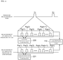
- FIG. 4 The same components described in FIGS. 1 and 3 are denoted by the same reference numerals.
- gas pressure determination unit 110 periodically measures pressure at predetermined time intervals T (e.g., two seconds to ten seconds).
- FIG. 4 illustrates pressure measurement times T1 and T2 that each indicate timing of pressure measurement.
- gas-side pressure value collector 201 collects absolute pressure values from pressure value Pg(1) measured first to pressure value Pg(n) measured at a maximum n-th time by gas-side absolute pressure sensor 105 at predetermined intervals (e.g., 5 ms).
- Atmosphere-side pressure value collector 202 collects absolute pressure values from pressure value Pa(1) measured first to pressure value Pa(n) measured at a maximum n-th time by atmosphere-side absolute pressure sensor 105 at the same timing as gas-side absolute pressure sensor 106.
- gas-side previous value comparator 220 compares first pressure value Pg(1) with second pressure value Pg(2), and thereafter, every time a measurement value is collected, gas-side previous value comparator 220 compares the measurement value with the previous value.
- atmosphere-side pressure value collector 202 collects second pressure value Pa(2)
- atmosphere-side previous value comparator 221 compares first pressure value Pa(1) with second pressure value Pa(2), and thereafter, every time a pressure value is collected
- atmosphere-side previous value comparator 221 compares the pressure value with the previous pressure value.
- drive-stop determination unit 205 stops driving gas-side absolute pressure sensor 105 and atmosphere-side absolute pressure sensor 106.
- a pressure value is stably measured by determining whether a difference between a pressure value acquired this time and a pressure value acquired last time is smaller than a predetermined value.
- the predetermined value may be equal or set individually on each of the gas side and the atmosphere side.
- Gas pressure determination unit 110 calculates gas supply pressure from a difference between a pressure value on the gas side in the (k+1)-th measurement with gas-side pressure value collector 201 when it is determined that measured pressure values are stable and a pressure value on the atmosphere side in the (k+1)-th measurement acquired by atmosphere-side pressure value collector 202. Then, control circuit 204 determines whether there is an anomaly such as gas leakage by determining flow-rate measurement data measured by flow rate measurement unit 103, gas supply pressure, and change in the gas supply pressure. When determining that there is an anomaly, control circuit 204 causes shutoff valve 102 to shut off flow path 101 to stop supplying the gas.
- an anomaly such as gas leakage by determining flow-rate measurement data measured by flow rate measurement unit 103, gas supply pressure, and change in the gas supply pressure.
- gas pressure determination unit 110 When it is determined that pressure values are unstable even after n repetitions as a result of comparisons using gas-side previous value comparator 220 and atmosphere-side previous value comparator 221 at pressure measurement time T1, as a result, gas pressure determination unit 110 does not calculate gas supply pressure from a difference between two absolute pressure values at pressure measurement time T1. Operation similar to that described above is also performed at pressure measurement time T2.
- measurements are performed by driving two absolute pressure sensors (gas-side absolute pressure sensor 105 being the first pressure sensor and atmosphere-side absolute pressure sensor 106 being the second pressure sensor) at predetermined time intervals T
- power consumption can be reduced due to control of driving and stopping of the two absolute pressure sensors, the control being performed by determining whether pressure values measured by the two absolute pressure sensors are stable.
- gas-side previous value comparator 220 and atmosphere-side previous value comparator 221 have been described as a method for comparing two measurement results at the previous time and the current time, it is needless to say that the same can be performed when drive-stop determination unit 205 performs sensor drive control by comparing an average of values at multiple times up to the previous time and a measurement value at the current time.
- gas-side absolute pressure sensor 105 is mounted on electronic circuit 107 installed in the gas atmosphere inside flow path 101
- gas-side absolute pressure sensor 105 may be mounted anywhere inside flow path 101.
- atmosphere-side absolute pressure sensor 106 is mounted on control circuit 104 installed on the atmospheric side outside flow path 101
- a mounting place is not limited as long as atmospheric pressure can be measured.
- a first disclosure includes a flow path for allowing gas to flow, a flow rate measurement unit for measuring a flow rate of the gas flowing through the flow path, a first pressure sensor disposed inside the flow path to measure absolute pressure of the gas, and a second pressure sensor disposed outside the flow path to measure absolute pressure of atmospheric pressure. Further provided are a pressure value transition detector that detects a transition state of absolute pressure measured by the first pressure sensor or the second pressure sensor, and a sensor drive controller that controls driving of the first pressure sensor or the second pressure sensor based on a transition value of the pressure value transition detector.
- a gas pressure determination unit that calculates gas supply pressure from a difference between pressure values measured when the first pressure sensor and the second pressure sensor are both driven, a shutoff valve that shuts off the flow path, and a control circuit that controls the flow rate measurement unit and causes the shutoff valve to shut off the flow path when determining anomaly from the flow rate measured by the flow rate measurement unit or the gas supply pressure calculated by the gas pressure determination unit.
- This configuration enables reducing power consumption by reducing the driving of the atmosphere-side absolute pressure sensor. Additionally, a through-hole required for using a pressure sensor of a differential pressure measurement type becomes unnecessary, and gas can be prevented from being ejected even at high temperature around the gas safety device, thereby enabling a gas safety device with higher safety to be fabricated.
- a second disclosure may be configured particularly in the first disclosure such that the flow rate measurement unit includes a measurement circuit disposed inside the flow path, the first pressure sensor is formed on the measurement circuit, the control circuit is disposed outside the flow path, and the second pressure sensor is disposed on the control circuit.
- a third disclosure may be configured particularly in the first or second disclosure such that the flow rate measurement unit includes an ultrasonic flow rate measurement unit in which an ultrasonic sensor and a measurement circuit that drives the ultrasonic sensor to measure a flow rate are integrated, the ultrasonic flow rate measurement unit is installed in gas atmosphere, the ultrasonic flow rate measurement unit includes the first pressure sensor, and the control circuit controls the ultrasonic flow rate measurement unit to also control the first pressure sensor on an ultrasonic sensor drive circuit.
- a fourth disclosure includes a flow path for allowing gas to flow, a flow rate measurement unit for measuring a flow rate of the gas flowing through the flow path, a first pressure sensor disposed inside the flow path to measure absolute pressure of the gas, and a second pressure sensor disposed outside the flow path to measure absolute pressure of atmospheric pressure.
- a first pressure value collector that collects n values of absolute pressure measured by the first pressure sensor
- a second pressure value collector that collects n values of absolute pressure measured by the second pressure sensor.
- first pressure previous value comparator that compares a current measurement value and a previous measurement value obtained by the first pressure value collector
- second pressure previous value comparator that compares a current measurement value and a previous measurement value obtained by the second pressure value collector
- drive-stop determination unit that determines stop of driving the sensors from results of the first pressure previous value comparator and the second pressure previous value comparator.
- a gas pressure determination unit that calculates gas supply pressure from a difference between absolute pressures measured by the first pressure value collector and the second pressure value collector, a shutoff valve that shuts off the flow path, and a control circuit that controls the flow rate measurement unit and causes the shutoff valve to shut off the flow path when determining anomaly from the flow rate measured by the flow rate measurement unit or the gas supply pressure calculated by the gas pressure determination unit.
- This configuration enables reducing power consumption by reducing the driving of the two absolute pressure sensors. Additionally, a through-hole required for using a pressure sensor of a differential pressure measurement type becomes unnecessary, and gas can be prevented from being ejected even at high temperature around the gas safety device, thereby enabling a gas safety device with higher safety to be fabricated.
- a fifth disclosure may be configured particularly in the fourth disclosure such that the flow rate measurement unit includes a measurement circuit disposed inside the flow path, the first pressure sensor is formed on the measurement circuit, the control circuit is disposed outside the flow path, and the second pressure sensor is disposed on the control circuit.
- a sixth disclosure may be configured particularly in the fourth or fifth disclosure such that the flow rate measurement unit includes an ultrasonic flow rate measurement unit in which an ultrasonic sensor and a measurement circuit that drives the ultrasonic sensor to measure a flow rate are integrated, the ultrasonic flow rate measurement unit is installed in gas atmosphere, the ultrasonic flow rate measurement unit includes a first pressure sensor, and the control circuit controls the ultrasonic flow rate measurement unit to also control the first pressure sensor on an ultrasonic sensor drive circuit.
- the present disclosure enables not only improving safety of a gas safety device but also fabricating an inexpensive gas safety device, and can be applied to applications such as gas meters for general household and business.
Landscapes
- Physics & Mathematics (AREA)
- General Physics & Mathematics (AREA)
- Fluid Mechanics (AREA)
- Electromagnetism (AREA)
- Engineering & Computer Science (AREA)
- Automation & Control Theory (AREA)
- Measuring Volume Flow (AREA)
Applications Claiming Priority (2)
| Application Number | Priority Date | Filing Date | Title |
|---|---|---|---|
| JP2019093462A JP7390544B2 (ja) | 2019-05-17 | 2019-05-17 | ガス保安装置 |
| PCT/JP2020/019151 WO2020235422A1 (fr) | 2019-05-17 | 2020-05-13 | Dispositif de sécurité de gaz |
Publications (3)
| Publication Number | Publication Date |
|---|---|
| EP3971538A1 true EP3971538A1 (fr) | 2022-03-23 |
| EP3971538A4 EP3971538A4 (fr) | 2022-07-13 |
| EP3971538B1 EP3971538B1 (fr) | 2024-09-25 |
Family
ID=73220985
Family Applications (1)
| Application Number | Title | Priority Date | Filing Date |
|---|---|---|---|
| EP20808824.5A Active EP3971538B1 (fr) | 2019-05-17 | 2020-05-13 | Dispositif de sécurité de gaz |
Country Status (7)
| Country | Link |
|---|---|
| US (1) | US11714434B2 (fr) |
| EP (1) | EP3971538B1 (fr) |
| JP (2) | JP7390544B2 (fr) |
| CN (1) | CN113811745B (fr) |
| DK (1) | DK3971538T3 (fr) |
| PL (1) | PL3971538T3 (fr) |
| WO (1) | WO2020235422A1 (fr) |
Families Citing this family (1)
| Publication number | Priority date | Publication date | Assignee | Title |
|---|---|---|---|---|
| US11525754B2 (en) * | 2020-10-30 | 2022-12-13 | Honeywell International Inc. | Leak detection system and method |
Family Cites Families (35)
| Publication number | Priority date | Publication date | Assignee | Title |
|---|---|---|---|---|
| US5911238A (en) * | 1996-10-04 | 1999-06-15 | Emerson Electric Co. | Thermal mass flowmeter and mass flow controller, flowmetering system and method |
| JP3508993B2 (ja) * | 1998-11-19 | 2004-03-22 | 矢崎総業株式会社 | 流量計測方法及び装置並びに電子式ガスメータ |
| JP4292643B2 (ja) * | 1999-09-09 | 2009-07-08 | パナソニック株式会社 | ガス圧力検知装置 |
| JP2001264142A (ja) * | 2000-03-16 | 2001-09-26 | Tokyo Gas Co Ltd | 流量計 |
| JP2002054968A (ja) * | 2000-08-09 | 2002-02-20 | Yazaki Corp | ガスメータ |
| JP2004077248A (ja) * | 2002-08-14 | 2004-03-11 | Tokyo Gas Co Ltd | 低消費電力でサンプリングレートが高い流量測定装置及びそれを利用したガスメータ |
| US6907790B2 (en) * | 2003-03-21 | 2005-06-21 | Rosemount Inc. | Gage pressure output from an absolute pressure measurement device |
| JP2005233437A (ja) * | 2004-02-17 | 2005-09-02 | Tokyo Gas Co Ltd | 圧力異常検知装置および圧力異常検知方法 |
| JP4867738B2 (ja) * | 2007-03-23 | 2012-02-01 | パナソニック株式会社 | ガス器具監視装置 |
| JP5032951B2 (ja) * | 2007-11-20 | 2012-09-26 | 大阪瓦斯株式会社 | ガス漏洩検知方法 |
| JP5140464B2 (ja) * | 2008-03-12 | 2013-02-06 | 東光東芝メーターシステムズ株式会社 | 超音波ガスメータ |
| JP5252718B2 (ja) * | 2008-10-23 | 2013-07-31 | パナソニック株式会社 | 流体遮断装置 |
| EP2383552B1 (fr) * | 2009-01-26 | 2020-12-23 | Panasonic Corporation | Dispositif d'interruption de gaz |
| JP5630075B2 (ja) * | 2010-06-03 | 2014-11-26 | パナソニック株式会社 | ガス遮断装置 |
| JP5867517B2 (ja) * | 2012-02-03 | 2016-02-24 | 日立金属株式会社 | 流量制御装置及びプログラム |
| JP6426475B2 (ja) * | 2012-03-07 | 2018-11-21 | イリノイ トゥール ワークス インコーポレイティド | 熱モデルを用いてrod測定における熱に起因する誤差を最小にすることによって質量流量制御器または質量流量計における実時間補正のための減衰速度測定の精度を改善するためのシステムおよび方法 |
| JP5960614B2 (ja) * | 2012-03-29 | 2016-08-02 | Ckd株式会社 | 流体制御システム、流体制御方法 |
| JP6060378B2 (ja) * | 2012-11-13 | 2017-01-18 | パナソニックIpマネジメント株式会社 | 流量計測装置 |
| US9605992B2 (en) * | 2014-03-14 | 2017-03-28 | Hitachi Metals, Ltd. | On-tool mass flow controller diagnostic systems and methods |
| JP2015145827A (ja) * | 2014-02-03 | 2015-08-13 | 矢崎エナジーシステム株式会社 | 計測流路ユニット |
| JP2015145826A (ja) * | 2014-02-03 | 2015-08-13 | 矢崎エナジーシステム株式会社 | ガスメータ |
| KR102097344B1 (ko) * | 2014-03-31 | 2020-04-06 | 히타치 긴조쿠 가부시키가이샤 | 질량 유량의 측정 방법, 당해 방법을 사용하는 열식 질량 유량계 및 당해 열식 질량 유량계를 사용하는 열식 질량 유량 제어 장치 |
| CN114796778B (zh) * | 2015-12-02 | 2026-04-03 | 费雪派克医疗保健有限公司 | 流量治疗设备的流动路径感测 |
| CN108779997A (zh) * | 2016-01-22 | 2018-11-09 | 伊利诺斯工具制品有限公司 | 动态地配置在质量流量控制器上存储的数据值的系统和方法 |
| US10866131B2 (en) * | 2016-09-19 | 2020-12-15 | Flow Devices And Systems Inc. | Systems and methods for reference volume for flow calibration |
| JP7457455B2 (ja) * | 2016-10-28 | 2024-03-28 | 株式会社堀場エステック | 流体制御弁用診断装置、流体制御装置、及び流体制御弁用診断プログラム |
| JP7245600B2 (ja) * | 2016-12-15 | 2023-03-24 | 株式会社堀場エステック | 流量制御装置、及び、流量制御装置用プログラム |
| US11105664B2 (en) * | 2017-03-23 | 2021-08-31 | Honeywell International Inc. | Apparatus and method for creating inferential process flow measurements using flow restrictor and upstream and downstream pressure measurements |
| CN110431508A (zh) * | 2017-03-28 | 2019-11-08 | 株式会社富士金 | 压力式流量控制裝置以及流量控制方法 |
| JP7012218B2 (ja) * | 2018-03-30 | 2022-01-28 | パナソニックIpマネジメント株式会社 | ガス保安装置 |
| CN111971636B (zh) * | 2018-04-19 | 2023-12-12 | 株式会社堀场Stec | 流量控制装置、诊断方法和存储介质 |
| ES2930200T3 (es) * | 2018-06-08 | 2022-12-07 | Panasonic Ip Man Co Ltd | Dispositivo de seguridad de gas |
| CN109141774B (zh) * | 2018-08-15 | 2020-02-21 | 山东拙诚智能科技有限公司 | 一种通过向燃气表注册用气设备实现燃气安全管理方法 |
| US10705543B2 (en) * | 2018-08-29 | 2020-07-07 | Illinois Tool Works, Inc. | Mass flow controller and controller algorithm |
| US11073845B2 (en) * | 2019-08-26 | 2021-07-27 | Hitachi Metals, Ltd. | Parasitic flow correction method and apparatus |
-
2019
- 2019-05-17 JP JP2019093462A patent/JP7390544B2/ja active Active
-
2020
- 2020-05-13 CN CN202080034874.2A patent/CN113811745B/zh active Active
- 2020-05-13 DK DK20808824.5T patent/DK3971538T3/da active
- 2020-05-13 WO PCT/JP2020/019151 patent/WO2020235422A1/fr not_active Ceased
- 2020-05-13 EP EP20808824.5A patent/EP3971538B1/fr active Active
- 2020-05-13 US US17/599,538 patent/US11714434B2/en active Active
- 2020-05-13 PL PL20808824.5T patent/PL3971538T3/pl unknown
-
2023
- 2023-06-05 JP JP2023092098A patent/JP7426600B2/ja active Active
Also Published As
| Publication number | Publication date |
|---|---|
| JP7390544B2 (ja) | 2023-12-04 |
| US11714434B2 (en) | 2023-08-01 |
| JP2020187082A (ja) | 2020-11-19 |
| EP3971538B1 (fr) | 2024-09-25 |
| PL3971538T3 (pl) | 2025-03-03 |
| US20220147069A1 (en) | 2022-05-12 |
| CN113811745B (zh) | 2024-02-06 |
| DK3971538T3 (da) | 2024-11-18 |
| CN113811745A (zh) | 2021-12-17 |
| WO2020235422A1 (fr) | 2020-11-26 |
| JP7426600B2 (ja) | 2024-02-02 |
| EP3971538A4 (fr) | 2022-07-13 |
| JP2023101798A (ja) | 2023-07-21 |
Similar Documents
| Publication | Publication Date | Title |
|---|---|---|
| EP2805136B1 (fr) | Système pour surveiller en temps réel un débit au travers de régulateurs de débit massique | |
| CN108139761B (zh) | 质量流量控制装置和压差式流量计的诊断方法 | |
| US8307845B2 (en) | Flow rate controller | |
| US10048160B2 (en) | Valve operation and diagnosis | |
| EP3117137B1 (fr) | Système de surveillance de débit à travers des régulateurs de débit massique en temps réel | |
| KR20180056710A (ko) | 유량 제어 장치 및 유량 제어 장치를 사용하는 이상 검지 방법 | |
| KR20170137880A (ko) | 압력식 유량 제어 장치 및 그 이상 검지 방법 | |
| ATE433098T1 (de) | Strömungsmessung | |
| EP3779376B1 (fr) | Dispositif de sécurité pour le gaz | |
| CA3001285A1 (fr) | Pompe intelligente pour instrument de detection de gaz portatif | |
| EP3971538B1 (fr) | Dispositif de sécurité de gaz | |
| KR102003156B1 (ko) | 메인터넌스 시기 예측 장치, 유량 제어 장치 및 메인터넌스 시기 예측 방법 | |
| US12013708B2 (en) | Gas safety device | |
| KR101951592B1 (ko) | 메인터넌스 판단 지표 추정 장치, 유량 제어 장치 및 메인터넌스 판단 지표 추정 방법 | |
| JP2023101797A (ja) | ガス保安装置 | |
| EP2869037A1 (fr) | Dispositif de mesure de débit | |
| JP2005267572A (ja) | 流量制御の異常判定方法及び装置 | |
| EP4056963A1 (fr) | Débit massique ultrasonique et thermique dans un seul canal d'écoulement | |
| JP2010055500A (ja) | 流量制御装置及び流量制御方法 | |
| JP2677133B2 (ja) | ガス圧力異常監視装置 |
Legal Events
| Date | Code | Title | Description |
|---|---|---|---|
| STAA | Information on the status of an ep patent application or granted ep patent |
Free format text: STATUS: THE INTERNATIONAL PUBLICATION HAS BEEN MADE |
|
| PUAI | Public reference made under article 153(3) epc to a published international application that has entered the european phase |
Free format text: ORIGINAL CODE: 0009012 |
|
| STAA | Information on the status of an ep patent application or granted ep patent |
Free format text: STATUS: REQUEST FOR EXAMINATION WAS MADE |
|
| 17P | Request for examination filed |
Effective date: 20211109 |
|
| AK | Designated contracting states |
Kind code of ref document: A1 Designated state(s): AL AT BE BG CH CY CZ DE DK EE ES FI FR GB GR HR HU IE IS IT LI LT LU LV MC MK MT NL NO PL PT RO RS SE SI SK SM TR |
|
| A4 | Supplementary search report drawn up and despatched |
Effective date: 20220615 |
|
| RIC1 | Information provided on ipc code assigned before grant |
Ipc: G01F 1/66 20220101ALI20220610BHEP Ipc: G01L 19/06 20060101ALI20220610BHEP Ipc: G01M 3/28 20060101ALI20220610BHEP Ipc: G01F 15/00 20060101ALI20220610BHEP Ipc: G01F 1/72 20060101ALI20220610BHEP Ipc: G01L 15/00 20060101ALI20220610BHEP Ipc: G01F 3/22 20060101AFI20220610BHEP |
|
| DAV | Request for validation of the european patent (deleted) | ||
| DAX | Request for extension of the european patent (deleted) | ||
| GRAP | Despatch of communication of intention to grant a patent |
Free format text: ORIGINAL CODE: EPIDOSNIGR1 |
|
| STAA | Information on the status of an ep patent application or granted ep patent |
Free format text: STATUS: GRANT OF PATENT IS INTENDED |
|
| INTG | Intention to grant announced |
Effective date: 20240430 |
|
| GRAS | Grant fee paid |
Free format text: ORIGINAL CODE: EPIDOSNIGR3 |
|
| GRAA | (expected) grant |
Free format text: ORIGINAL CODE: 0009210 |
|
| STAA | Information on the status of an ep patent application or granted ep patent |
Free format text: STATUS: THE PATENT HAS BEEN GRANTED |
|
| AK | Designated contracting states |
Kind code of ref document: B1 Designated state(s): AL AT BE BG CH CY CZ DE DK EE ES FI FR GB GR HR HU IE IS IT LI LT LU LV MC MK MT NL NO PL PT RO RS SE SI SK SM TR |
|
| REG | Reference to a national code |
Ref country code: GB Ref legal event code: FG4D |
|
| REG | Reference to a national code |
Ref country code: CH Ref legal event code: EP |
|
| REG | Reference to a national code |
Ref country code: DE Ref legal event code: R096 Ref document number: 602020038399 Country of ref document: DE |
|
| REG | Reference to a national code |
Ref country code: IE Ref legal event code: FG4D |
|
| REG | Reference to a national code |
Ref country code: DK Ref legal event code: T3 Effective date: 20241115 |
|
| REG | Reference to a national code |
Ref country code: LT Ref legal event code: MG9D |
|
| PG25 | Lapsed in a contracting state [announced via postgrant information from national office to epo] |
Ref country code: NO Free format text: LAPSE BECAUSE OF FAILURE TO SUBMIT A TRANSLATION OF THE DESCRIPTION OR TO PAY THE FEE WITHIN THE PRESCRIBED TIME-LIMIT Effective date: 20241225 |
|
| PG25 | Lapsed in a contracting state [announced via postgrant information from national office to epo] |
Ref country code: GR Free format text: LAPSE BECAUSE OF FAILURE TO SUBMIT A TRANSLATION OF THE DESCRIPTION OR TO PAY THE FEE WITHIN THE PRESCRIBED TIME-LIMIT Effective date: 20241226 Ref country code: FI Free format text: LAPSE BECAUSE OF FAILURE TO SUBMIT A TRANSLATION OF THE DESCRIPTION OR TO PAY THE FEE WITHIN THE PRESCRIBED TIME-LIMIT Effective date: 20240925 |
|
| PG25 | Lapsed in a contracting state [announced via postgrant information from national office to epo] |
Ref country code: BG Free format text: LAPSE BECAUSE OF FAILURE TO SUBMIT A TRANSLATION OF THE DESCRIPTION OR TO PAY THE FEE WITHIN THE PRESCRIBED TIME-LIMIT Effective date: 20240925 |
|
| PG25 | Lapsed in a contracting state [announced via postgrant information from national office to epo] |
Ref country code: LV Free format text: LAPSE BECAUSE OF FAILURE TO SUBMIT A TRANSLATION OF THE DESCRIPTION OR TO PAY THE FEE WITHIN THE PRESCRIBED TIME-LIMIT Effective date: 20240925 |
|
| PG25 | Lapsed in a contracting state [announced via postgrant information from national office to epo] |
Ref country code: RS Free format text: LAPSE BECAUSE OF FAILURE TO SUBMIT A TRANSLATION OF THE DESCRIPTION OR TO PAY THE FEE WITHIN THE PRESCRIBED TIME-LIMIT Effective date: 20241225 |
|
| REG | Reference to a national code |
Ref country code: NL Ref legal event code: MP Effective date: 20240925 |
|
| PG25 | Lapsed in a contracting state [announced via postgrant information from national office to epo] |
Ref country code: RS Free format text: LAPSE BECAUSE OF FAILURE TO SUBMIT A TRANSLATION OF THE DESCRIPTION OR TO PAY THE FEE WITHIN THE PRESCRIBED TIME-LIMIT Effective date: 20241225 Ref country code: NO Free format text: LAPSE BECAUSE OF FAILURE TO SUBMIT A TRANSLATION OF THE DESCRIPTION OR TO PAY THE FEE WITHIN THE PRESCRIBED TIME-LIMIT Effective date: 20241225 Ref country code: LV Free format text: LAPSE BECAUSE OF FAILURE TO SUBMIT A TRANSLATION OF THE DESCRIPTION OR TO PAY THE FEE WITHIN THE PRESCRIBED TIME-LIMIT Effective date: 20240925 Ref country code: GR Free format text: LAPSE BECAUSE OF FAILURE TO SUBMIT A TRANSLATION OF THE DESCRIPTION OR TO PAY THE FEE WITHIN THE PRESCRIBED TIME-LIMIT Effective date: 20241226 Ref country code: FI Free format text: LAPSE BECAUSE OF FAILURE TO SUBMIT A TRANSLATION OF THE DESCRIPTION OR TO PAY THE FEE WITHIN THE PRESCRIBED TIME-LIMIT Effective date: 20240925 Ref country code: BG Free format text: LAPSE BECAUSE OF FAILURE TO SUBMIT A TRANSLATION OF THE DESCRIPTION OR TO PAY THE FEE WITHIN THE PRESCRIBED TIME-LIMIT Effective date: 20240925 |
|
| REG | Reference to a national code |
Ref country code: AT Ref legal event code: MK05 Ref document number: 1726969 Country of ref document: AT Kind code of ref document: T Effective date: 20240925 |
|
| PG25 | Lapsed in a contracting state [announced via postgrant information from national office to epo] |
Ref country code: NL Free format text: LAPSE BECAUSE OF FAILURE TO SUBMIT A TRANSLATION OF THE DESCRIPTION OR TO PAY THE FEE WITHIN THE PRESCRIBED TIME-LIMIT Effective date: 20240925 |
|
| PG25 | Lapsed in a contracting state [announced via postgrant information from national office to epo] |
Ref country code: PT Free format text: LAPSE BECAUSE OF FAILURE TO SUBMIT A TRANSLATION OF THE DESCRIPTION OR TO PAY THE FEE WITHIN THE PRESCRIBED TIME-LIMIT Effective date: 20250127 Ref country code: IS Free format text: LAPSE BECAUSE OF FAILURE TO SUBMIT A TRANSLATION OF THE DESCRIPTION OR TO PAY THE FEE WITHIN THE PRESCRIBED TIME-LIMIT Effective date: 20250125 |
|
| PG25 | Lapsed in a contracting state [announced via postgrant information from national office to epo] |
Ref country code: SM Free format text: LAPSE BECAUSE OF FAILURE TO SUBMIT A TRANSLATION OF THE DESCRIPTION OR TO PAY THE FEE WITHIN THE PRESCRIBED TIME-LIMIT Effective date: 20240925 Ref country code: RO Free format text: LAPSE BECAUSE OF FAILURE TO SUBMIT A TRANSLATION OF THE DESCRIPTION OR TO PAY THE FEE WITHIN THE PRESCRIBED TIME-LIMIT Effective date: 20240925 |
|
| PG25 | Lapsed in a contracting state [announced via postgrant information from national office to epo] |
Ref country code: ES Free format text: LAPSE BECAUSE OF FAILURE TO SUBMIT A TRANSLATION OF THE DESCRIPTION OR TO PAY THE FEE WITHIN THE PRESCRIBED TIME-LIMIT Effective date: 20240925 |
|
| PG25 | Lapsed in a contracting state [announced via postgrant information from national office to epo] |
Ref country code: AT Free format text: LAPSE BECAUSE OF FAILURE TO SUBMIT A TRANSLATION OF THE DESCRIPTION OR TO PAY THE FEE WITHIN THE PRESCRIBED TIME-LIMIT Effective date: 20240925 Ref country code: EE Free format text: LAPSE BECAUSE OF FAILURE TO SUBMIT A TRANSLATION OF THE DESCRIPTION OR TO PAY THE FEE WITHIN THE PRESCRIBED TIME-LIMIT Effective date: 20240925 |
|
| PG25 | Lapsed in a contracting state [announced via postgrant information from national office to epo] |
Ref country code: SK Free format text: LAPSE BECAUSE OF FAILURE TO SUBMIT A TRANSLATION OF THE DESCRIPTION OR TO PAY THE FEE WITHIN THE PRESCRIBED TIME-LIMIT Effective date: 20240925 |
|
| REG | Reference to a national code |
Ref country code: DE Ref legal event code: R097 Ref document number: 602020038399 Country of ref document: DE |
|
| PGFP | Annual fee paid to national office [announced via postgrant information from national office to epo] |
Ref country code: PL Payment date: 20250506 Year of fee payment: 6 |
|
| PGFP | Annual fee paid to national office [announced via postgrant information from national office to epo] |
Ref country code: GB Payment date: 20250527 Year of fee payment: 6 Ref country code: DK Payment date: 20250526 Year of fee payment: 6 |
|
| PGFP | Annual fee paid to national office [announced via postgrant information from national office to epo] |
Ref country code: BE Payment date: 20250521 Year of fee payment: 6 Ref country code: IT Payment date: 20250527 Year of fee payment: 6 |
|
| PGFP | Annual fee paid to national office [announced via postgrant information from national office to epo] |
Ref country code: TR Payment date: 20250506 Year of fee payment: 6 |
|
| PGFP | Annual fee paid to national office [announced via postgrant information from national office to epo] |
Ref country code: CZ Payment date: 20250506 Year of fee payment: 6 |
|
| PLBE | No opposition filed within time limit |
Free format text: ORIGINAL CODE: 0009261 |
|
| STAA | Information on the status of an ep patent application or granted ep patent |
Free format text: STATUS: NO OPPOSITION FILED WITHIN TIME LIMIT |
|
| 26N | No opposition filed |
Effective date: 20250626 |
|
| PG25 | Lapsed in a contracting state [announced via postgrant information from national office to epo] |
Ref country code: SE Free format text: LAPSE BECAUSE OF FAILURE TO SUBMIT A TRANSLATION OF THE DESCRIPTION OR TO PAY THE FEE WITHIN THE PRESCRIBED TIME-LIMIT Effective date: 20240925 |
|
| REG | Reference to a national code |
Ref country code: DE Ref legal event code: R119 Ref document number: 602020038399 Country of ref document: DE |
|
| REG | Reference to a national code |
Ref country code: CH Ref legal event code: H13 Free format text: ST27 STATUS EVENT CODE: U-0-0-H10-H13 (AS PROVIDED BY THE NATIONAL OFFICE) Effective date: 20251223 |
|
| PG25 | Lapsed in a contracting state [announced via postgrant information from national office to epo] |
Ref country code: HR Free format text: LAPSE BECAUSE OF FAILURE TO SUBMIT A TRANSLATION OF THE DESCRIPTION OR TO PAY THE FEE WITHIN THE PRESCRIBED TIME-LIMIT Effective date: 20240925 Ref country code: LU Free format text: LAPSE BECAUSE OF NON-PAYMENT OF DUE FEES Effective date: 20250513 |
|
| PG25 | Lapsed in a contracting state [announced via postgrant information from national office to epo] |
Ref country code: CH Free format text: LAPSE BECAUSE OF NON-PAYMENT OF DUE FEES Effective date: 20250531 |
|
| PG25 | Lapsed in a contracting state [announced via postgrant information from national office to epo] |
Ref country code: MC Free format text: LAPSE BECAUSE OF FAILURE TO SUBMIT A TRANSLATION OF THE DESCRIPTION OR TO PAY THE FEE WITHIN THE PRESCRIBED TIME-LIMIT Effective date: 20240925 |
|
| PG25 | Lapsed in a contracting state [announced via postgrant information from national office to epo] |
Ref country code: IE Free format text: LAPSE BECAUSE OF NON-PAYMENT OF DUE FEES Effective date: 20250513 Ref country code: DE Free format text: LAPSE BECAUSE OF NON-PAYMENT OF DUE FEES Effective date: 20251202 |
|
| REG | Reference to a national code |
Ref country code: GB Ref legal event code: 746 Effective date: 20260320 |
|
| PG25 | Lapsed in a contracting state [announced via postgrant information from national office to epo] |
Ref country code: FR Free format text: LAPSE BECAUSE OF NON-PAYMENT OF DUE FEES Effective date: 20250531 |