EP3971561B1 - Kalibrierinformationseinstellungsvorrichtung, messvorrichtung, kalibrierinformationseinstellungsverfahren, messverfahren, kalibrierinformationseinstellungsprogramm und messprogramm - Google Patents
Kalibrierinformationseinstellungsvorrichtung, messvorrichtung, kalibrierinformationseinstellungsverfahren, messverfahren, kalibrierinformationseinstellungsprogramm und messprogramm Download PDFInfo
- Publication number
- EP3971561B1 EP3971561B1 EP20806406.3A EP20806406A EP3971561B1 EP 3971561 B1 EP3971561 B1 EP 3971561B1 EP 20806406 A EP20806406 A EP 20806406A EP 3971561 B1 EP3971561 B1 EP 3971561B1
- Authority
- EP
- European Patent Office
- Prior art keywords
- signal
- intensity
- calibration information
- observation
- variable attenuator
- Prior art date
- Legal status (The legal status is an assumption and is not a legal conclusion. Google has not performed a legal analysis and makes no representation as to the accuracy of the status listed.)
- Active
Links
Images




Classifications
-
- G—PHYSICS
- G01—MEASURING; TESTING
- G01N—INVESTIGATING OR ANALYSING MATERIALS BY DETERMINING THEIR CHEMICAL OR PHYSICAL PROPERTIES
- G01N22/00—Investigating or analysing materials by the use of microwaves or radio waves, i.e. electromagnetic waves with a wavelength of one millimetre or more
-
- G—PHYSICS
- G01—MEASURING; TESTING
- G01N—INVESTIGATING OR ANALYSING MATERIALS BY DETERMINING THEIR CHEMICAL OR PHYSICAL PROPERTIES
- G01N33/00—Investigating or analysing materials by specific methods not covered by groups G01N1/00 - G01N31/00
- G01N33/18—Water
-
- G—PHYSICS
- G01—MEASURING; TESTING
- G01S—RADIO DIRECTION-FINDING; RADIO NAVIGATION; DETERMINING DISTANCE OR VELOCITY BY USE OF RADIO WAVES; LOCATING OR PRESENCE-DETECTING BY USE OF THE REFLECTION OR RERADIATION OF RADIO WAVES; ANALOGOUS ARRANGEMENTS USING OTHER WAVES
- G01S13/00—Systems using the reflection or reradiation of radio waves, e.g. radar systems; Analogous systems using reflection or reradiation of waves whose nature or wavelength is irrelevant or unspecified
- G01S13/88—Radar or analogous systems specially adapted for specific applications
- G01S13/95—Radar or analogous systems specially adapted for specific applications for meteorological use
-
- G—PHYSICS
- G01—MEASURING; TESTING
- G01W—METEOROLOGY
- G01W1/00—Meteorology
-
- G—PHYSICS
- G01—MEASURING; TESTING
- G01N—INVESTIGATING OR ANALYSING MATERIALS BY DETERMINING THEIR CHEMICAL OR PHYSICAL PROPERTIES
- G01N22/00—Investigating or analysing materials by the use of microwaves or radio waves, i.e. electromagnetic waves with a wavelength of one millimetre or more
- G01N22/04—Investigating moisture content
Definitions
- the present invention relates to a technique for observing a specific radio frequency (RF) signal such as a radiated electromagnetic wave generated by water vapor.
- RF radio frequency
- Patent Document 1 Conventionally, an observation device for water vapor as shown in Patent Document 1 is known.
- Terahertz Superconducting Radiometric Spectrometer in Egypt for Atmospheric Science by Li et al. (Journal of Infrared, Millimeter and Terahertz Waves, 20181217 Springer New York LLC, US - ISSN 1866-6892, Vol:40, Nr:2, Page(s):166 - 177 ) is concerned with a terahertz superconducting radiometric spectrometer that is a dual-band heterodyne receiver system based on high sensitive superconductor-insulator-superconductor mixers which cover the frequency range of 180 to 380 GHz.
- JP H11 264736 A discloses a frequency changing part that changes an input signal into an intermediate frequency and a level detecting part that outputs a level detection signal proportionate to the logarithm of a signal level.
- a gain control part that corrects a frequency characteristic of the frequency changing part according to an instruction of a control part.
- a corrective means that is inserted in the middle of a gain control signal path for making an appropriate temperature correction.
- Patent Document 1 Japanese Patent Laid-Open No. 2013 (-224884)
- One method of observing water vapor is to use an intensity of radiated electromagnetic waves (RF signals).
- RF signals radiated electromagnetic waves
- the error of the observation result can be reduced.
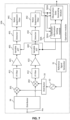
- the observation device 10 includes a mixer 20, a reference signal generator 31, a local signal generator 32, an intermediate frequency (IF) filter 41, an amplifier 42, a detector 43, a noise suppression filter 44, an operation module 50, and a variable attenuator (variable ATT) 60.
- the calculation module 50 includes a calibration information setting module 501 and an observation data generating module 502.
- the mixer 20, the local signal generator 32, the IF filter 41, the amplifier 42, the detector 43, the noise suppression filter 44, and the variable attenuator (variable ATT) 60 can be realized, for example, by a predetermined analog electronic circuit.
- the reference signal generator 31 and the operation module 50 can be realized by, for example, an arithmetic element such as a CPU and a program executed by the arithmetic element.
- the observation device 10 has an input terminal Pin.
- the input terminal Pin is connected to an antenna ANT via a first stage low noise amplifier (LNA) (not shown).
- LNA low noise amplifier
- the input terminal Pin is connected to the mixer 20.
- the mixer 20 is directly connected to the first stage LNA.
- the local signal generator 32 is connected to the mixer 20.
- the local signal generator 32 is connected to a reference signal generator 31.
- the reference signal generator 31 is connected to the calculation module 50.
- the antenna ANT receives an electromagnetic wave radiated from a black radiator (blackbody) 90 or an electromagnetic wave radiated from water vapor to be observed.
- the RF signal (electromagnetic wave) received by the antenna ANT is inputted to the input terminal Pin via the first stage LNA.
- the RF signal input to the input terminal Pin is input to the mixer 20.
- the reference signal generator 31 generates, for example, a reference signal composed of sawtooth waves.
- the reference signal generator 31 outputs the reference signal to the local signal generator 32 and the operation module 50.
- the local signal generator 32 generates a local signal of a predetermined frequency based on the reference signal.
- a frequency of the local signal is set within a frequency range of a frequency spectrum of an observation object.
- the local signal generator 32 individually generates local signals of a plurality of frequencies. In other words, the local signal generator 32 generates the local signals of the plurality of frequencies at different timings.
- the local signal generator 32 outputs the local signal to the mixer 20.
- the mixer 20 mixes the RF signal and the local signal to down-convert them to generate an IF signal.
- the mixer 20 outputs the IF signal to the IF filter 41.
- the IF filter 41 has filter characteristics including a frequency necessary for generating observation data of the observation object in a pass region and other noise components in an attenuation region.
- the IF filter 41 filters the IF signal and outputs it to the amplifier 42.
- the amplifier 42 amplifies the IF signal and outputs it to the variable attenuator 60.
- the variable attenuator 60 has a circuit configuration capable of adjusting an attenuation of the IF signal.
- An attenuation of the variable attenuator 60 can be set, for example, by the calibration information setting module 501 of the operation module 50.
- the IF signal that has passed through the variable attenuator 60 is input to the detector 43.
- the detector 43 detects the IF signal and outputs a detection signal.
- the noise suppression filter 44 is realized by, for example, a smoothing filter.
- the noise suppression filter 44 suppresses a noise component of the detection signal and outputs it to the operation module 50.
- the calibration information setting module 501 which will be described later in detail, sets calibration information for calibrating errors caused by the circuits up to the detector 43 including the detector 43.
- the calibration information setting module 501 outputs the calibration information to the observation data generating module 502.
- the observation data generating module 502 generates the observation data by using a detection signal (reference detection signal) obtained in a state where the blackbody 90 covers a reception surface of the antenna ANT and a detection signal (observation object detection signal) obtained in a state where the blackbody 90 is removed from the reception surface of the antenna ANT.
- a detection signal reference detection signal
- observation object detection signal observation object detection signal
- the observation data generating module 502 receives the reference detection signal and the observation object detection signal in a state where the attenuation of the variable attenuator 60 is fixed.
- the observation data generating module 502 generates the observation data from a difference (intensity difference) between an intensity of the reference detection signal and an intensity of the observation object detection signal.
- the observation data generating module 502 calculates an intensity difference for each of a plurality of frequency components of the RF signal. Thus, the observation data generating module 502 obtains the frequency spectrum of the radiated electromagnetic wave for the phenomenon to be observed as the observation data.
- the observation data generating module 502 performs calibration in advance using the calibration information.
- errors due to the detector 43 and the like included in the intensity difference are suppressed. Therefore, the observation data becomes a highly accurate value (value with little error) corresponding to the intensity of the radiation electromagnetic wave of the observation object.
- the detector 43 generally has, for example, a temperature characteristic. Note that, although circuit elements (electronic devices) other than the detector 43 also have temperature characteristics, in the present application, the detector 43, which has a large influence on the output due to the temperature characteristics, will be mainly described. Accordingly, the intensity of the detection signal varies depending on a temperature of the detector 43, for example, an environmental temperature of the observation device 10. As described above, when the intensity of the detection signal changes depending on the environmental temperature, an error occurs in the observation data. Therefore, the observation device 10 sets the calibration information according to the following concept and uses it for the generation of the observation data.
- FIG. 2A is a graph showing a relationship between the intensity of the detected signal and an attenuation amount
- FIG. 2B is a graph showing the definition of the intensity difference.
- the calibration information is set, for example, in a state where the blackbody 90 covers the receiving surface of the antenna ANT. It should be noted that the blackbody 90 need not be used as long as the environment in which an RF signal having a constant signal intensity is input to the antenna ANT can be maintained.
- the calibration information setting module 501 adjusts the attenuation of the variable attenuator 60 and acquires an intensity of the detection signal for the plurality of attenuation amounts.
- the set attenuation amount is set within a range necessary for generation of the observation data, and the number of set attenuation amount can be appropriately set.
- the calibration information setting module 501 calculates an amount of change ⁇ Pt of the intensity of the detection signal with respect to an amount of change ⁇ ATT of the attenuation of the variable attenuator 60, as shown in FIG. 2A , from the relationship between the difference of the plurality of attenuation amounts and the difference of the intensity of the detection signal with respect to each attenuation amount.
- the calibration information setting module 501 may calculate the amount of change ⁇ Pt by calculating an average value or the like by using a plurality of sets of the difference between the plurality of attenuation amounts and the difference in intensity of the detection signal with respect to each attenuation amount.
- an amount of change ⁇ Pt1 (a rate of change Kt1 of the signal intensity) of the detected signal intensity at a temperature t1 with respect to the amount of change ⁇ ATT of the attenuation of the variable attenuator 60 at the temperature t1 is different from an amount of change ⁇ Pt2 (a rate of change Kt2 of the signal intensity) of the detected signal intensity at a temperature t2 with respect to the amount of change ⁇ ATT of the attenuation of the variable attenuator 60 at the temperature t2.
- the calibration information setting module 501 calculates a rate of change Kt of the intensity depending on the temperature. Then, the calibration information setting module 501 calculates the calibration information, for example, by using the rate of change Kt as the calibration information or by using the rate of change Kt.
- the calibration information appropriately reflects the temperature characteristic of the detector 43 or the like.
- the observation data generating module 502 generates the observation data from the difference (intensity difference) between the intensity of the reference detection signal and the intensity of the observation object detection signal, as described above.
- the observation data generating module 502 generates the observation data from, for example, an intensity difference ⁇ P1, an intensity difference ⁇ P2, and an intensity difference ⁇ P3 shown in FIG. 2B . That is, the observation data generating module 502 generates the observation data from the intensity difference between the detection signals in the two different states.
- the observation data generating module 502 can accurately calibrate the intensity difference of the detection signal, and can generate a highly accurate observation data.
- the observation data generating module 502 normalizes the intensity difference between the reference detection signal and the observation object detection signal by using the rate of change Kt.
- the observation data generating module 502 can suppress an error caused by the temperature characteristic or the like of the detector 43 and generate a high-precision observation data.
- the two different states are a state in which radiated electromagnetic waves are received from the blackbody 90 and a state in which radiated electromagnetic waves are received from water vapor. Therefore, the observation device 10 can generate the observation data corresponding to the intensity of the radiation electromagnetic wave of water vapor with high accuracy.
- the observation device 10 can generate an observation data of a phenomenon to be observed, such as water vapor, with high accuracy.
- the observation device 10 can set calibration information only by generating a detection signal while adjusting the attenuation using the variable attenuator 60. That is, the observation device 10 can set the calibration information with a simple configuration and simple processing, and can generate a highly accurate observation data.
- FIG. 3 is an equivalent circuit diagram showing an example of the circuit configuration of the variable attenuator 60.
- the variable attenuator 60 includes a variable impedance circuit 661, a fixed resistance circuit 662, and a fixed resistance circuit 663.
- the fixed resistance circuit 662 corresponds to the "first fixed resistance circuit” of the present invention
- the fixed resistance circuit 663 corresponds to the "second fixed resistance circuit” of the present invention.
- variable impedance circuit 661, the fixed resistance circuit 662, and the fixed resistance circuit 663 are connected in series. At this time, the variable impedance circuit 661 is connected between the fixed resistance circuit 662 and the fixed resistance circuit 663.
- the fixed resistance circuit 662 is connected to the output terminal of the amplifier 42, and the fixed resistance circuit 663 is connected to the detector 43.
- the variable impedance circuit 661 is a circuit including a resistance element and a semiconductor element, and changes impedance (resistance value) by a control signal flowing in the semiconductor element.
- the fixed resistance circuit 662 and the fixed resistance circuit 663 have, for example, a circuit configuration in which a plurality of resistance elements are connected in a predetermined pattern.
- the fixed resistance circuit 662 functions as an impedance matching circuit between the variable impedance circuit 661 and the amplifier 42.
- the fixed resistance circuit 663 functions as an impedance matching circuit between the variable impedance circuit 661 and the detector 43.
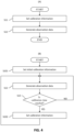
- FIG. 4A is a flow chart showing a first mode of the main process executed by the observation device 10
- FIG. 4B is a flow chart showing a second mode of the main process executed by the observation device 10.
- a computing device constituting the observation device 10 sets calibration information ( S11 ).
- An arithmetic module generates an observation data by using the calibration information ( S12 ).
- This processing shows a case where the calibration information is set and used at the beginning of observation. This method may be used when the observation time is short.
- the arithmetic module sets initial calibration information ( S101 ).
- the arithmetic module generates an observation data by using the initial calibration information ( S12 ).
- the arithmetic module has a time counting function and repeats the process of generating the observation data by using the initial calibration information ( S12 ) until a calibration time is reached ( S13 : NO).
- the arithmetic module can continuously generate a high-precision observation data.
- the arithmetic module can continuously generate the high-precision observation data while reducing the processing load.
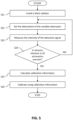
- FIG. 5 is a flow chart showing an example of a specific method of setting calibration information.
- the blackbody 90 is installed on the receiving surface of the antenna ANT ( S21 ).
- the arrangement of the blackbody 90 may be mechanically controlled by providing a moving mechanism for the blackbody 90 on the antenna ANT or manually.
- the arithmetic module sets the attenuation of the variable attenuator 60 ( S22 ).
- the arithmetic module measures the intensity of the detection signal obtained by the set attenuation amount of the variable attenuator 60 ( S23 ).
- the arithmetic module preliminarily sets the range of all attenuation amounts for obtaining the intensity difference necessary for generating the observation data. If the intensity of the detection signal is not obtained in all attenuation amounts ( S24 : NO), the arithmetic module changes the attenuation setting of the variable attenuator 60 ( S22 ), and measures the intensity of the detection signal ( S23 ).
- the arithmetic module calculates the calibration information from the difference in the intensity of the detection signal in the different attenuation amounts, that is, the rate of change of the intensity ( S25 ). Using the calibration information, the arithmetic module performs calibration for the measurement of the intensity described later ( S26 ).
- the blackbody 90 is installed on the receiving surface of the antenna ANT ( S32 ).
- the arrangement of the blackbody 90 may be mechanically controlled by providing a moving mechanism for the blackbody 90 on the antenna ANT or manually.
- the arithmetic module measures the intensity of the reference detection signal ( S33 ).
- the blackbody 90 is removed from the receiving surface of the antenna ANT ( S34 ).
- the removal of the blackbody 90 may be mechanically controlled by providing a moving mechanism for the blackbody 90 on the antenna ANT, or may be performed manually.
- the arithmetic module measures the intensity of the observation object detection signal ( S35 ).
- the arithmetic module calculates an intensity difference between the intensity of the reference detection signal and the intensity of the observation object detection signal ( S36 ).
- the arithmetic module generates an observation data from the intensity difference, that is, observes water vapor ( S37 ).
- FIG. 7 is a block diagram showing a configuration of an observation device 10A according to a second embodiment.
- the observation device 10A according to the second embodiment differs from the observation device 10 according to the first embodiment in that the detection signals are measured in parallel by a plurality of circuits.
- the configuration and processing of the observation device 10A are the same as those of the observation device 10, and the description of the same points is omitted.
- the distributor 33 is connected to the local signal generator 32, the mixer 201, and the mixer 202.
- the distributor 34 is connected to the input terminal Pin, the mixer 201, and the mixer 202.
- the mixer 202 is connected to the IF filter 412, and the IF filter 412 is connected to the amplifier 422.
- the amplifier 422 is connected to the variable attenuator 602, and the variable attenuator 602 is connected to the detector 432.
- the detector 432 is connected to the noise suppression filter 442, and the noise suppression filter 442 is connected to the operation module 50A.
- the mixer 201 and the mixer 202 have the same configuration as the mixer 20 described above.
- the IF filter 411 and the IF filter 412 have the same configuration as the IF filter 41 described above except for the filter characteristics.
- the IF filter 411 has filter characteristics including a first intermediate frequency f(IF1) in a pass region and a second intermediate frequency f(IF2) in an attenuation region.
- the IF filter 412 has filter characteristics including the second intermediate frequency f(IF2) in a pass region and the first intermediate frequency f(IF1) in an attenuation region.
- the first intermediate frequency f(IF1) is set to a frequency obtained by subtracting the frequency of the RF signal from the frequency of the local signal.
- the second intermediate frequency f(IF2) is set to a frequency obtained by subtracting the frequency of the local signal from the frequency of the RF signal.
- variable attenuator 601 and the variable attenuator 602 have the same configuration as the variable attenuator 60 described above.
- a control signal is inputted to the variable attenuator 601 and the variable attenuator 602 from the calibration information setting module 501A.
- the detector 431 and the detector 432 have the same configuration as the detector 43 described above.
- the noise suppression filter 441 and the noise suppression filter 442 have the same configuration as that of the noise suppression filter 44.
- the distributor 33 distributes the local signal and outputs it to the mixer 201 and the mixer 202.
- the distributor 34 distributes the RF signal and outputs it to the mixer 201 and the mixer 202.
- the mixer 201 mixes the RF signal and the local signal and outputs a first IF signal.
- the mixer 202 mixes the RF signal and the local signal and outputs a second IF signal.
- the first IF signal and the second IF signal are the same signal.
- the amplified first IF signal is inputted to the detector 431 via the variable attenuator 601.
- the amplified second IF signal is inputted to the detector 432 via the variable attenuator 602.
- the detector 431 detects the amplified first IF signal and outputs a first detection signal.
- the detector 432 detects the amplified second IF signal and outputs a second detection signal.
- the noise suppression filter 441 suppresses a noise component of the first detection signal and outputs it to the operation module 50A.
- the noise suppression filter 442 suppresses a noise component of the second detection signal and outputs it to the operation module 50A.
- the calibration information setting module 501A sets calibration information (calibration information) for a first detection signal by using a change of an intensity of the first detection signal acquired by changing the attenuation of the variable attenuator 601 in a state that the blackbody 90 is arranged on the antenna ANT.
- the calibration information setting module 501A sets calibration information (second calibration information) for the second detection signal by using a change in the intensity of the second detection signal acquired by changing the attenuation of the variable attenuator 602 in a state where the blackbody 90 is arranged on the antenna ANT.
- the calibration information setting module 501A outputs the calibration information to the observation data generating module 502A.
- the observation data generating module 502A generates observation data by using a difference in the intensity of the first detection signal acquired in a state where the blackbody 90 is arranged on the antenna ANT and a state where the blackbody 90 is removed from the antenna ANT, and a difference in the intensity of the second detection signal acquired in a state where the blackbody 90 is arranged on the antenna ANT and a state where the blackbody 90 is removed from the antenna ANT.
- the observation data generating module 502A uses the first calibration information to calibrate the intensity difference of the first detection signal and uses the second calibration information to calibrate the intensity difference of the second detection signal.
- detection signals for RF signals of two frequencies are obtained from local signals of one frequency. Accordingly, the observation device 10A obtains the predetermined number of frequency spectrum components by the half number of local signals. The observation device 10A obtains a frequency spectrum of a predetermined frequency band by a local signal in a frequency band narrower than the predetermined frequency band. Thus, the observation device 10A can generate an observation data composed of a frequency spectrum having the predetermined frequency band with simpler processing while narrowing a frequency band set as a local signal.
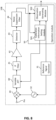
- FIG. 9 is a block diagram showing a configuration of an observation device 10C according to a fourth embodiment.
- the variable attenuator 60 is connected between the IF filter 41 and the amplifier 42.
- the calibration information setting module 501 can set calibration information capable of suppressing an error caused by the amplifier 42 and an error caused by the detector 43.
- the configuration of the observation device 10B according to the third embodiment and the configuration of the observation device 10C according to the fourth embodiment can also be applied to the observation device 10A according to the second embodiment, and effects corresponding to the respective combinations can be obtained.
Landscapes
- Physics & Mathematics (AREA)
- Life Sciences & Earth Sciences (AREA)
- Engineering & Computer Science (AREA)
- Chemical & Material Sciences (AREA)
- Health & Medical Sciences (AREA)
- General Physics & Mathematics (AREA)
- Pathology (AREA)
- Immunology (AREA)
- Biochemistry (AREA)
- General Health & Medical Sciences (AREA)
- Analytical Chemistry (AREA)
- Radar, Positioning & Navigation (AREA)
- Remote Sensing (AREA)
- Food Science & Technology (AREA)
- Electromagnetism (AREA)
- Medicinal Chemistry (AREA)
- Environmental & Geological Engineering (AREA)
- Atmospheric Sciences (AREA)
- Biodiversity & Conservation Biology (AREA)
- Ecology (AREA)
- Environmental Sciences (AREA)
- Computer Networks & Wireless Communication (AREA)
- Radar Systems Or Details Thereof (AREA)
- Radiation Pyrometers (AREA)
Claims (7)
- Beobachtungsvorrichtung (10), aufweisend:einen Referenzsignalgenerator (31), der konfiguriert ist, um ein Referenzsignal auszugeben;einen lokalen Signalgenerator (32), der konfiguriert ist, um ein lokales Signal basierend auf dem Referenzsignal zu erzeugen;einen Mischer (20), der konfiguriert ist, um das lokale Signal und ein Hochfrequenz-, RF-, Signal eines Beobachtungsobjekts zu mischen, um das RF-Signal in ein Zwischenfrequenz-, IF-, Signal herunterzuwandeln;einen Detektor (43), der konfiguriert ist, um das IF-Signal zu detektieren und um ein Detektionssignal zu erzeugen;einen variablen Dämpfer (60), der zwischen dem Mischer (20) und dem Detektor (43) verbunden ist, der konfiguriert ist, um das IF-Signal zu dämpfen;ein Kalibrierungsinformationseinstellmodul (501), das konfiguriert ist, um Kalibrierungsinformationen aus einer Beziehung zwischen einer Änderung in einer Dämpfung des variablen Dämpfers (60) und einer Änderung in einer Intensität des Detektionssignals einzustellen; undein Beobachtungsdatengeneratormodul (502), das konfiguriert ist, um Beobachtungsdaten des RF-Signals unter Verwendung der Intensität des Detektionssignals, das in einem Zustand erhalten wird, in dem der Wert des variablen Dämpfers fest ist, und der Kalibrierungsinformationen zu erzeugen, wobei:das RF-Signal des Beobachtungsobjekts durch elektromagnetische Wellen erzeugt wird, die von einer Umgebung, die eine konstante Signalintensität verursacht, und von Wasserdampf abgestrahlt werden, unddie Beobachtungsdaten eine Differenz zwischen der Intensität des RF-Signals aufgrund der elektromagnetischen Welle, die von der Umgebung abgestrahlt wird, die eine konstante Signalintensität verursacht, und der Intensität des RF-Signals aufgrund der elektromagnetischen Welle, die von dem Wasserdampf abgestrahlt wird, sind.
- Beobachtungsvorrichtung (10) nach Anspruch 1, wobei
die elektromagnetische Welle, die von der Umgebung abgestrahlt wird, die eine konstante Signalintensität verursacht, eine elektromagnetische Welle ist, die von einem schwarzen Körper (90) abgestrahlt wird. - Beobachtungsvorrichtung (10) nach Anspruch 2, wobei:
die Kalibrierungsinformationen für jede Frequenz des IF-Signals eingestellt werden. - Beobachtungsvorrichtung (10) nach Anspruch 2 oder Anspruch 3, wobei:
der variable Dämpfer (60) aufweist:eine erste Festwiderstandsschaltung (662) und eine zweite Festwiderstandsschaltung (663), die jeweils eine Vielzahl von Widerstandselementen verwenden; undeine variable Impedanzschaltung (661), die einen Halbleiter verwendet, wobei die variable Impedanzschaltung (661) zwischen der ersten Festwiderstandsschaltung (662) und der zweiten Festwiderstandsschaltung (663) verbunden ist. - Beobachtungsvorrichtung (10) nach einem der Ansprüche 2 bis 4, ferner aufweisend:einen IF-Filter (41), der zwischen dem Mischer (20) und dem Detektor (43) verbunden ist; undeinen Verstärker (42), der zwischen dem IF-Filter (41) und dem Detektor (43) verbunden ist; wobei der variable Dämpfer (60) zwischen dem Mischer (20) und dem Verstärker (42) angeordnet ist.
- Beobachtungsverfahren, aufweisend:Erzeugen eines Referenzsignals;Erzeugen eines lokalen Signals basierend auf dem Referenzsignal;Mischen des lokalen Signals und eines Hochfrequenz-, RF-, Signals eines Beobachtungsobjekts, um das RF-Signal in ein Zwischenfrequenz-, IF-, Signal herunterzuwandeln;Detektieren des IF-Signals, um ein Detektionssignal zu erzeugen; undEinstellen von Kalibrierungsinformationen aus einer Beziehung zwischen einer Änderung in der Dämpfung in Bezug auf das IF-Signal und einer Änderung in der Intensität des Detektionssignals;Erzeugen von Beobachtungsdaten des RF-Signals unter Verwendung der Intensität des Detektionssignals, das in einem Zustand erhalten wird, in dem die Dämpfung fest ist, und der Kalibrierungsinformationen, wobei:das RF-Signal des Beobachtungsobjekts durch elektromagnetische Wellen erzeugt wird, die von Wasserdampf abgestrahlt werden, unddie Beobachtungsdaten eine Differenz zwischen der Intensität eines RF-Signals aufgrund der elektromagnetischen Welle, die von einer Umgebung abgestrahlt wird, die eine konstante Signalintensität verursacht, und der Intensität des RF-Signals aufgrund der elektromagnetischen Welle, die von dem Wasserdampf abgestrahlt wird, sind.
- Nichtflüchtiges computerlesbares Medium, auf dem computerausführbare Anweisungen gespeichert sind, die, wenn sie durch die Beobachtungsvorrichtung nach Anspruch 1 ausgeführt werden, die Beobachtungsvorrichtung veranlassen, das Verfahren nach Anspruch 6 auszuführen.
Applications Claiming Priority (2)
| Application Number | Priority Date | Filing Date | Title |
|---|---|---|---|
| JP2019091266 | 2019-05-14 | ||
| PCT/JP2020/016417 WO2020230503A1 (ja) | 2019-05-14 | 2020-04-14 | 校正情報設定装置、観測装置、校正情報設定方法、観測方法、校正情報設定プログラム、および、観測プログラム |
Publications (3)
| Publication Number | Publication Date |
|---|---|
| EP3971561A1 EP3971561A1 (de) | 2022-03-23 |
| EP3971561A4 EP3971561A4 (de) | 2023-01-11 |
| EP3971561B1 true EP3971561B1 (de) | 2025-03-19 |
Family
ID=73289524
Family Applications (1)
| Application Number | Title | Priority Date | Filing Date |
|---|---|---|---|
| EP20806406.3A Active EP3971561B1 (de) | 2019-05-14 | 2020-04-14 | Kalibrierinformationseinstellungsvorrichtung, messvorrichtung, kalibrierinformationseinstellungsverfahren, messverfahren, kalibrierinformationseinstellungsprogramm und messprogramm |
Country Status (5)
| Country | Link |
|---|---|
| US (1) | US12038391B2 (de) |
| EP (1) | EP3971561B1 (de) |
| JP (1) | JP7491912B2 (de) |
| CN (1) | CN113677982A (de) |
| WO (1) | WO2020230503A1 (de) |
Families Citing this family (1)
| Publication number | Priority date | Publication date | Assignee | Title |
|---|---|---|---|---|
| CN117723639B (zh) * | 2023-12-19 | 2024-06-14 | 中国计量科学研究院 | 一种超声探伤仪检定校准装置 |
Family Cites Families (9)
| Publication number | Priority date | Publication date | Assignee | Title |
|---|---|---|---|---|
| JPS55165277U (de) * | 1979-05-17 | 1980-11-27 | ||
| JPH083505B2 (ja) * | 1988-04-11 | 1996-01-17 | アンリツ株式会社 | スペクトラムアナライザ |
| JP2681997B2 (ja) | 1988-04-30 | 1997-11-26 | 日本電気株式会社 | マイクロ波放射計受信機 |
| JPH11264736A (ja) * | 1998-03-17 | 1999-09-28 | Matsushita Electric Ind Co Ltd | 選択レベル計測モジュール及び計測システム |
| EP1037337B1 (de) * | 1998-10-04 | 2008-05-14 | The Furukawa Electric Co., Ltd. | Optischer verstärker |
| AR054423A3 (es) * | 2006-01-11 | 2007-06-27 | Spinlock S R L | Un aparato y metodo para medir el caudal y el corte de petroleo y agua de la produccion petrolera en tiempo y caudales reales |
| JP6099318B2 (ja) | 2012-04-23 | 2017-03-22 | 日本無線株式会社 | 水蒸気観測装置および気象レーダ |
| CN105548975B (zh) * | 2015-12-11 | 2017-11-10 | 中国科学院电子学研究所 | 高稳定性射频信道增益校准装置和方法 |
| AT520436B1 (de) * | 2017-09-13 | 2019-04-15 | UBIMET GmbH | Verfahren zur Ermittlung zumindest einer meteorologischen Größe zur Beschreibung einer Zustandsform atmosphärischen Wassers |
-
2020
- 2020-04-14 CN CN202080027533.2A patent/CN113677982A/zh not_active Withdrawn
- 2020-04-14 EP EP20806406.3A patent/EP3971561B1/de active Active
- 2020-04-14 WO PCT/JP2020/016417 patent/WO2020230503A1/ja not_active Ceased
- 2020-04-14 JP JP2021519312A patent/JP7491912B2/ja active Active
-
2021
- 2021-11-01 US US17/453,142 patent/US12038391B2/en active Active
Also Published As
| Publication number | Publication date |
|---|---|
| US12038391B2 (en) | 2024-07-16 |
| WO2020230503A1 (ja) | 2020-11-19 |
| JP7491912B2 (ja) | 2024-05-28 |
| EP3971561A1 (de) | 2022-03-23 |
| CN113677982A (zh) | 2021-11-19 |
| JPWO2020230503A1 (de) | 2020-11-19 |
| US20220050063A1 (en) | 2022-02-17 |
| EP3971561A4 (de) | 2023-01-11 |
Similar Documents
| Publication | Publication Date | Title |
|---|---|---|
| US8145166B2 (en) | Enhanced programmable automatic level control | |
| US10615891B2 (en) | Receiver testing | |
| KR101856756B1 (ko) | 신호 발생기 및 신호 발생기를 포함하는 측정 시스템 | |
| US10509106B2 (en) | Method for calibrating a radar system | |
| US10330775B2 (en) | Transmitter, transmission method, phase adjustment device, and phase adjustment method | |
| KR102313253B1 (ko) | 무선 주파수 장치 및 대응 방법 | |
| US9007259B1 (en) | Flight line noise tester | |
| CN113900071B (zh) | 输出功率检测电路、调节方法、检测方法及相控阵雷达 | |
| US9667282B1 (en) | Method and apparatus for adaptive gain control and antenna load compensation | |
| US10225027B2 (en) | Device and method for calibrating a wideband radio frequency receive chain | |
| KR102720686B1 (ko) | 위상변환기를 갖는 rf체인에 대한 루프백 이득 스텝 교정을 위한 방법 | |
| CN109347509B (zh) | 一种有源天线的增益补偿方法、装置与有源天线 | |
| US20160344484A1 (en) | Wireless communication device and wireless communication system | |
| US12038391B2 (en) | Observation device, and observation method | |
| JP6452145B2 (ja) | レーダ装置の信号処理装置、レーダ装置、および校正式作成方法 | |
| US6628923B1 (en) | Adaptive phase and amplitude linearization method and apparatus | |
| US9148103B2 (en) | Gain measurement circuit, gain measurement method, and communication apparatus | |
| KR101494390B1 (ko) | 근접전계시험 데이터 보상방법 및 이를 이용한 레이더 및 센서 | |
| US11237197B1 (en) | Method and systems for making improved quasi-linear/nonlinear measurements on integrated antenna arrays and elements | |
| US11121787B2 (en) | Method, system and apparatus for calibration of phased array radio frequency transceiver | |
| US20250112663A1 (en) | On-chip noise measurement in a transceiver, method and system thereof | |
| US20260072068A1 (en) | Test and/or measurement system and method | |
| KR102591192B1 (ko) | 시스템 성능 안정화를 위한 신호 보상 피드백 회로 및 알고리즘이 적용된 rf 시스템 및 그 동작 방법 | |
| Laundrie | Noise-Related Technologies Climb Toward THz Territory | |
| Evdokimov et al. | Development of Band-Pass Filter for Increasing the Possible Gain in Transponder |
Legal Events
| Date | Code | Title | Description |
|---|---|---|---|
| STAA | Information on the status of an ep patent application or granted ep patent |
Free format text: STATUS: THE INTERNATIONAL PUBLICATION HAS BEEN MADE |
|
| PUAI | Public reference made under article 153(3) epc to a published international application that has entered the european phase |
Free format text: ORIGINAL CODE: 0009012 |
|
| STAA | Information on the status of an ep patent application or granted ep patent |
Free format text: STATUS: REQUEST FOR EXAMINATION WAS MADE |
|
| 17P | Request for examination filed |
Effective date: 20211111 |
|
| AK | Designated contracting states |
Kind code of ref document: A1 Designated state(s): AL AT BE BG CH CY CZ DE DK EE ES FI FR GB GR HR HU IE IS IT LI LT LU LV MC MK MT NL NO PL PT RO RS SE SI SK SM TR |
|
| DAV | Request for validation of the european patent (deleted) | ||
| DAX | Request for extension of the european patent (deleted) | ||
| A4 | Supplementary search report drawn up and despatched |
Effective date: 20221212 |
|
| RIC1 | Information provided on ipc code assigned before grant |
Ipc: G01S 13/95 20060101ALI20221206BHEP Ipc: G01W 1/00 20060101ALI20221206BHEP Ipc: G01N 22/04 20060101AFI20221206BHEP |
|
| GRAP | Despatch of communication of intention to grant a patent |
Free format text: ORIGINAL CODE: EPIDOSNIGR1 |
|
| STAA | Information on the status of an ep patent application or granted ep patent |
Free format text: STATUS: GRANT OF PATENT IS INTENDED |
|
| INTG | Intention to grant announced |
Effective date: 20241118 |
|
| GRAS | Grant fee paid |
Free format text: ORIGINAL CODE: EPIDOSNIGR3 |
|
| GRAA | (expected) grant |
Free format text: ORIGINAL CODE: 0009210 |
|
| STAA | Information on the status of an ep patent application or granted ep patent |
Free format text: STATUS: THE PATENT HAS BEEN GRANTED |
|
| AK | Designated contracting states |
Kind code of ref document: B1 Designated state(s): AL AT BE BG CH CY CZ DE DK EE ES FI FR GB GR HR HU IE IS IT LI LT LU LV MC MK MT NL NO PL PT RO RS SE SI SK SM TR |
|
| REG | Reference to a national code |
Ref country code: GB Ref legal event code: FG4D |
|
| REG | Reference to a national code |
Ref country code: CH Ref legal event code: EP |
|
| REG | Reference to a national code |
Ref country code: DE Ref legal event code: R096 Ref document number: 602020048012 Country of ref document: DE |
|
| REG | Reference to a national code |
Ref country code: IE Ref legal event code: FG4D |
|
| PG25 | Lapsed in a contracting state [announced via postgrant information from national office to epo] |
Ref country code: RS Free format text: LAPSE BECAUSE OF FAILURE TO SUBMIT A TRANSLATION OF THE DESCRIPTION OR TO PAY THE FEE WITHIN THE PRESCRIBED TIME-LIMIT Effective date: 20250619 |
|
| PG25 | Lapsed in a contracting state [announced via postgrant information from national office to epo] |
Ref country code: FI Free format text: LAPSE BECAUSE OF FAILURE TO SUBMIT A TRANSLATION OF THE DESCRIPTION OR TO PAY THE FEE WITHIN THE PRESCRIBED TIME-LIMIT Effective date: 20250319 |
|
| PGFP | Annual fee paid to national office [announced via postgrant information from national office to epo] |
Ref country code: DE Payment date: 20250415 Year of fee payment: 6 |
|
| REG | Reference to a national code |
Ref country code: LT Ref legal event code: MG9D |
|
| PG25 | Lapsed in a contracting state [announced via postgrant information from national office to epo] |
Ref country code: NO Free format text: LAPSE BECAUSE OF FAILURE TO SUBMIT A TRANSLATION OF THE DESCRIPTION OR TO PAY THE FEE WITHIN THE PRESCRIBED TIME-LIMIT Effective date: 20250619 |
|
| PG25 | Lapsed in a contracting state [announced via postgrant information from national office to epo] |
Ref country code: HR Free format text: LAPSE BECAUSE OF FAILURE TO SUBMIT A TRANSLATION OF THE DESCRIPTION OR TO PAY THE FEE WITHIN THE PRESCRIBED TIME-LIMIT Effective date: 20250319 |
|
| PG25 | Lapsed in a contracting state [announced via postgrant information from national office to epo] |
Ref country code: LV Free format text: LAPSE BECAUSE OF FAILURE TO SUBMIT A TRANSLATION OF THE DESCRIPTION OR TO PAY THE FEE WITHIN THE PRESCRIBED TIME-LIMIT Effective date: 20250319 |
|
| PG25 | Lapsed in a contracting state [announced via postgrant information from national office to epo] |
Ref country code: GR Free format text: LAPSE BECAUSE OF FAILURE TO SUBMIT A TRANSLATION OF THE DESCRIPTION OR TO PAY THE FEE WITHIN THE PRESCRIBED TIME-LIMIT Effective date: 20250620 Ref country code: BG Free format text: LAPSE BECAUSE OF FAILURE TO SUBMIT A TRANSLATION OF THE DESCRIPTION OR TO PAY THE FEE WITHIN THE PRESCRIBED TIME-LIMIT Effective date: 20250319 |
|
| REG | Reference to a national code |
Ref country code: NL Ref legal event code: MP Effective date: 20250319 |
|
| REG | Reference to a national code |
Ref country code: AT Ref legal event code: MK05 Ref document number: 1777323 Country of ref document: AT Kind code of ref document: T Effective date: 20250319 |
|
| PG25 | Lapsed in a contracting state [announced via postgrant information from national office to epo] |
Ref country code: NL Free format text: LAPSE BECAUSE OF FAILURE TO SUBMIT A TRANSLATION OF THE DESCRIPTION OR TO PAY THE FEE WITHIN THE PRESCRIBED TIME-LIMIT Effective date: 20250319 |
|
| PG25 | Lapsed in a contracting state [announced via postgrant information from national office to epo] |
Ref country code: SE Free format text: LAPSE BECAUSE OF FAILURE TO SUBMIT A TRANSLATION OF THE DESCRIPTION OR TO PAY THE FEE WITHIN THE PRESCRIBED TIME-LIMIT Effective date: 20250319 |
|
| PG25 | Lapsed in a contracting state [announced via postgrant information from national office to epo] |
Ref country code: SM Free format text: LAPSE BECAUSE OF FAILURE TO SUBMIT A TRANSLATION OF THE DESCRIPTION OR TO PAY THE FEE WITHIN THE PRESCRIBED TIME-LIMIT Effective date: 20250319 |
|
| PG25 | Lapsed in a contracting state [announced via postgrant information from national office to epo] |
Ref country code: ES Free format text: LAPSE BECAUSE OF FAILURE TO SUBMIT A TRANSLATION OF THE DESCRIPTION OR TO PAY THE FEE WITHIN THE PRESCRIBED TIME-LIMIT Effective date: 20250319 Ref country code: PT Free format text: LAPSE BECAUSE OF FAILURE TO SUBMIT A TRANSLATION OF THE DESCRIPTION OR TO PAY THE FEE WITHIN THE PRESCRIBED TIME-LIMIT Effective date: 20250721 |
|
| PG25 | Lapsed in a contracting state [announced via postgrant information from national office to epo] |
Ref country code: IT Free format text: LAPSE BECAUSE OF FAILURE TO SUBMIT A TRANSLATION OF THE DESCRIPTION OR TO PAY THE FEE WITHIN THE PRESCRIBED TIME-LIMIT Effective date: 20250319 Ref country code: PL Free format text: LAPSE BECAUSE OF FAILURE TO SUBMIT A TRANSLATION OF THE DESCRIPTION OR TO PAY THE FEE WITHIN THE PRESCRIBED TIME-LIMIT Effective date: 20250319 |
|
| PG25 | Lapsed in a contracting state [announced via postgrant information from national office to epo] |
Ref country code: AT Free format text: LAPSE BECAUSE OF FAILURE TO SUBMIT A TRANSLATION OF THE DESCRIPTION OR TO PAY THE FEE WITHIN THE PRESCRIBED TIME-LIMIT Effective date: 20250319 |
|
| PG25 | Lapsed in a contracting state [announced via postgrant information from national office to epo] |
Ref country code: CZ Free format text: LAPSE BECAUSE OF FAILURE TO SUBMIT A TRANSLATION OF THE DESCRIPTION OR TO PAY THE FEE WITHIN THE PRESCRIBED TIME-LIMIT Effective date: 20250319 Ref country code: EE Free format text: LAPSE BECAUSE OF FAILURE TO SUBMIT A TRANSLATION OF THE DESCRIPTION OR TO PAY THE FEE WITHIN THE PRESCRIBED TIME-LIMIT Effective date: 20250319 |
|
| PG25 | Lapsed in a contracting state [announced via postgrant information from national office to epo] |
Ref country code: RO Free format text: LAPSE BECAUSE OF FAILURE TO SUBMIT A TRANSLATION OF THE DESCRIPTION OR TO PAY THE FEE WITHIN THE PRESCRIBED TIME-LIMIT Effective date: 20250319 |
|
| PG25 | Lapsed in a contracting state [announced via postgrant information from national office to epo] |
Ref country code: SK Free format text: LAPSE BECAUSE OF FAILURE TO SUBMIT A TRANSLATION OF THE DESCRIPTION OR TO PAY THE FEE WITHIN THE PRESCRIBED TIME-LIMIT Effective date: 20250319 |
|
| PG25 | Lapsed in a contracting state [announced via postgrant information from national office to epo] |
Ref country code: IS Free format text: LAPSE BECAUSE OF FAILURE TO SUBMIT A TRANSLATION OF THE DESCRIPTION OR TO PAY THE FEE WITHIN THE PRESCRIBED TIME-LIMIT Effective date: 20250719 |
|
| REG | Reference to a national code |
Ref country code: CH Ref legal event code: H13 Free format text: ST27 STATUS EVENT CODE: U-0-0-H10-H13 (AS PROVIDED BY THE NATIONAL OFFICE) Effective date: 20251125 |
|
| PG25 | Lapsed in a contracting state [announced via postgrant information from national office to epo] |
Ref country code: LU Free format text: LAPSE BECAUSE OF NON-PAYMENT OF DUE FEES Effective date: 20250414 |
|
| PG25 | Lapsed in a contracting state [announced via postgrant information from national office to epo] |
Ref country code: MC Free format text: LAPSE BECAUSE OF FAILURE TO SUBMIT A TRANSLATION OF THE DESCRIPTION OR TO PAY THE FEE WITHIN THE PRESCRIBED TIME-LIMIT Effective date: 20250319 |
|
| REG | Reference to a national code |
Ref country code: DE Ref legal event code: R097 Ref document number: 602020048012 Country of ref document: DE |
|
| REG | Reference to a national code |
Ref country code: BE Ref legal event code: MM Effective date: 20250430 |
|
| PG25 | Lapsed in a contracting state [announced via postgrant information from national office to epo] |
Ref country code: DK Free format text: LAPSE BECAUSE OF FAILURE TO SUBMIT A TRANSLATION OF THE DESCRIPTION OR TO PAY THE FEE WITHIN THE PRESCRIBED TIME-LIMIT Effective date: 20250319 |
|
| PG25 | Lapsed in a contracting state [announced via postgrant information from national office to epo] |
Ref country code: BE Free format text: LAPSE BECAUSE OF NON-PAYMENT OF DUE FEES Effective date: 20250430 |
|
| PG25 | Lapsed in a contracting state [announced via postgrant information from national office to epo] |
Ref country code: CH Free format text: LAPSE BECAUSE OF NON-PAYMENT OF DUE FEES Effective date: 20250430 |
|
| PLBE | No opposition filed within time limit |
Free format text: ORIGINAL CODE: 0009261 |
|
| STAA | Information on the status of an ep patent application or granted ep patent |
Free format text: STATUS: NO OPPOSITION FILED WITHIN TIME LIMIT |
|
| REG | Reference to a national code |
Ref country code: CH Ref legal event code: L10 Free format text: ST27 STATUS EVENT CODE: U-0-0-L10-L00 (AS PROVIDED BY THE NATIONAL OFFICE) Effective date: 20260128 |
|
| 26N | No opposition filed |
Effective date: 20251222 |
|
| GBPC | Gb: european patent ceased through non-payment of renewal fee |
Effective date: 20250619 |
|
| PG25 | Lapsed in a contracting state [announced via postgrant information from national office to epo] |
Ref country code: GB Free format text: LAPSE BECAUSE OF NON-PAYMENT OF DUE FEES Effective date: 20250619 |
|
| PG25 | Lapsed in a contracting state [announced via postgrant information from national office to epo] |
Ref country code: IE Free format text: LAPSE BECAUSE OF NON-PAYMENT OF DUE FEES Effective date: 20250414 |
|
| PG25 | Lapsed in a contracting state [announced via postgrant information from national office to epo] |
Ref country code: FR Free format text: LAPSE BECAUSE OF NON-PAYMENT OF DUE FEES Effective date: 20250519 |