EP3971671B1 - Système et procédé d'identification et de prévision de l'encrassement des échangeurs de chaleur dans une raffinerie - Google Patents
Système et procédé d'identification et de prévision de l'encrassement des échangeurs de chaleur dans une raffinerie Download PDFInfo
- Publication number
- EP3971671B1 EP3971671B1 EP21197077.7A EP21197077A EP3971671B1 EP 3971671 B1 EP3971671 B1 EP 3971671B1 EP 21197077 A EP21197077 A EP 21197077A EP 3971671 B1 EP3971671 B1 EP 3971671B1
- Authority
- EP
- European Patent Office
- Prior art keywords
- fouling
- heat exchangers
- heat exchanger
- parameters
- data
- Prior art date
- Legal status (The legal status is an assumption and is not a legal conclusion. Google has not performed a legal analysis and makes no representation as to the accuracy of the status listed.)
- Active
Links
Images





Classifications
-
- G—PHYSICS
- G06—COMPUTING OR CALCULATING; COUNTING
- G06F—ELECTRIC DIGITAL DATA PROCESSING
- G06F30/00—Computer-aided design [CAD]
- G06F30/20—Design optimisation, verification or simulation
- G06F30/27—Design optimisation, verification or simulation using machine learning, e.g. artificial intelligence, neural networks, support vector machines [SVM] or training a model
-
- C—CHEMISTRY; METALLURGY
- C10—PETROLEUM, GAS OR COKE INDUSTRIES; TECHNICAL GASES CONTAINING CARBON MONOXIDE; FUELS; LUBRICANTS; PEAT
- C10G—CRACKING HYDROCARBON OILS; PRODUCTION OF LIQUID HYDROCARBON MIXTURES, e.g. BY DESTRUCTIVE HYDROGENATION, OLIGOMERISATION, POLYMERISATION; RECOVERY OF HYDROCARBON OILS FROM OIL-SHALE, OIL-SAND, OR GASES; REFINING MIXTURES MAINLY CONSISTING OF HYDROCARBONS; REFORMING OF NAPHTHA; MINERAL WAXES
- C10G75/00—Inhibiting corrosion or fouling in apparatus for treatment or conversion of hydrocarbon oils, in general
-
- F—MECHANICAL ENGINEERING; LIGHTING; HEATING; WEAPONS; BLASTING
- F28—HEAT EXCHANGE IN GENERAL
- F28F—DETAILS OF HEAT-EXCHANGE AND HEAT-TRANSFER APPARATUS, OF GENERAL APPLICATION
- F28F19/00—Preventing the formation of deposits or corrosion, e.g. by using filters or scrapers
-
- G—PHYSICS
- G05—CONTROLLING; REGULATING
- G05B—CONTROL OR REGULATING SYSTEMS IN GENERAL; FUNCTIONAL ELEMENTS OF SUCH SYSTEMS; MONITORING OR TESTING ARRANGEMENTS FOR SUCH SYSTEMS OR ELEMENTS
- G05B23/00—Testing or monitoring of control systems or parts thereof
- G05B23/02—Electric testing or monitoring
- G05B23/0205—Electric testing or monitoring by means of a monitoring system capable of detecting and responding to faults
- G05B23/0218—Electric testing or monitoring by means of a monitoring system capable of detecting and responding to faults characterised by the fault detection method dealing with either existing or incipient faults
- G05B23/0221—Preprocessing measurements, e.g. data collection rate adjustment; Standardization of measurements; Time series or signal analysis, e.g. frequency analysis or wavelets; Trustworthiness of measurements; Indexes therefor; Measurements using easily measured parameters to estimate parameters difficult to measure; Virtual sensor creation; De-noising; Sensor fusion; Unconventional preprocessing inherently present in specific fault detection methods like PCA-based methods
-
- G—PHYSICS
- G05—CONTROLLING; REGULATING
- G05B—CONTROL OR REGULATING SYSTEMS IN GENERAL; FUNCTIONAL ELEMENTS OF SUCH SYSTEMS; MONITORING OR TESTING ARRANGEMENTS FOR SUCH SYSTEMS OR ELEMENTS
- G05B23/00—Testing or monitoring of control systems or parts thereof
- G05B23/02—Electric testing or monitoring
- G05B23/0205—Electric testing or monitoring by means of a monitoring system capable of detecting and responding to faults
- G05B23/0259—Electric testing or monitoring by means of a monitoring system capable of detecting and responding to faults characterized by the response to fault detection
- G05B23/0283—Predictive maintenance, e.g. involving the monitoring of a system and, based on the monitoring results, taking decisions on the maintenance schedule of the monitored system; Estimating remaining useful life [RUL]
-
- G—PHYSICS
- G06—COMPUTING OR CALCULATING; COUNTING
- G06F—ELECTRIC DIGITAL DATA PROCESSING
- G06F18/00—Pattern recognition
- G06F18/20—Analysing
- G06F18/21—Design or setup of recognition systems or techniques; Extraction of features in feature space; Blind source separation
- G06F18/217—Validation; Performance evaluation; Active pattern learning techniques
-
- G—PHYSICS
- G06—COMPUTING OR CALCULATING; COUNTING
- G06F—ELECTRIC DIGITAL DATA PROCESSING
- G06F30/00—Computer-aided design [CAD]
- G06F30/20—Design optimisation, verification or simulation
- G06F30/23—Design optimisation, verification or simulation using finite element methods [FEM] or finite difference methods [FDM]
-
- G—PHYSICS
- G06—COMPUTING OR CALCULATING; COUNTING
- G06N—COMPUTING ARRANGEMENTS BASED ON SPECIFIC COMPUTATIONAL MODELS
- G06N20/00—Machine learning
-
- G—PHYSICS
- G06—COMPUTING OR CALCULATING; COUNTING
- G06N—COMPUTING ARRANGEMENTS BASED ON SPECIFIC COMPUTATIONAL MODELS
- G06N5/00—Computing arrangements using knowledge-based models
- G06N5/02—Knowledge representation; Symbolic representation
- G06N5/022—Knowledge engineering; Knowledge acquisition
-
- G—PHYSICS
- G06—COMPUTING OR CALCULATING; COUNTING
- G06N—COMPUTING ARRANGEMENTS BASED ON SPECIFIC COMPUTATIONAL MODELS
- G06N5/00—Computing arrangements using knowledge-based models
- G06N5/04—Inference or reasoning models
- G06N5/046—Forward inferencing; Production systems
-
- F—MECHANICAL ENGINEERING; LIGHTING; HEATING; WEAPONS; BLASTING
- F28—HEAT EXCHANGE IN GENERAL
- F28F—DETAILS OF HEAT-EXCHANGE AND HEAT-TRANSFER APPARATUS, OF GENERAL APPLICATION
- F28F2200/00—Prediction; Simulation; Testing
-
- G—PHYSICS
- G06—COMPUTING OR CALCULATING; COUNTING
- G06F—ELECTRIC DIGITAL DATA PROCESSING
- G06F2119/00—Details relating to the type or aim of the analysis or the optimisation
- G06F2119/02—Reliability analysis or reliability optimisation; Failure analysis, e.g. worst case scenario performance, failure mode and effects analysis [FMEA]
-
- G—PHYSICS
- G06—COMPUTING OR CALCULATING; COUNTING
- G06F—ELECTRIC DIGITAL DATA PROCESSING
- G06F2119/00—Details relating to the type or aim of the analysis or the optimisation
- G06F2119/08—Thermal analysis or thermal optimisation
Definitions
- the disclosure herein generally relates to the field of refinery, and, more particularly, to a method and a system for identification and forecasting fouling of heat exchangers in refinery such as an oil and gas refinery.
- Fouling is formation of deposits on the heat exchanger surfaces that adversely affects a heat exchange and other functions of the heat exchanger. Crude oil from storage tanks is fed to the heat exchangers of the crude pre-heat train. Fouling occurs due one or more of combinations of various reasons such as sedimentation, crystallization, biological growth, chemical reactions, or corrosion products freezing among others.
- Fouling in the refinery heat exchangers may also be caused by inorganic compounds, carbon deposition etc.
- transfer line exchangers undergo fouling due to carbon deposition
- pre-heat train heat exchangers undergo fouling due asphaltene deposition.
- Fouling of heat exchangers in petroleum refining industry leads to several problems such as - operating problems - decline in furnace inlet temperatures, reduced efficiency of heat recovery units, high operating costs - increased fuel consumption, high pumping power, increased carbon footprint, reduced throughput, increased maintenance costs and fouling in upstream heat exchangers.
- a method of controlling cooling water treatment may involve measuring operating data of one or more downstream heat exchangers that receive cooling water from the cooling tower. For example, the inlet and outlet temperatures of both the hot and cold streams of a downstream heat exchanger may be measured. Data from the streams passing through the heat exchanger may be used to determine a heat transfer efficiency for the heat exchanger. The heat transfer efficiency can be trended over a period of time and changes in the trend detected to identify cooling water fouling issues.
- the HEN retrofit structures are optimized, considering various heat intensification methods.
- the model is formulated based on the novel concept of Shifted Retrofit Thermodynamic Grid Diagram (SRTGD).
- SRTGD Shifted Retrofit Thermodynamic Grid Diagram
- MILP Mixed Integer Linear Programming
- the operating life of the network is discretized into multiple periods, and a decision is made within each period: whether to upgrade the heat exchangers, purchase new heat exchangers - for replacement or adding to the network, maintain the heat exchangers or perform nothing.
- Two realistic case studies are used to elucidate the application of the method.
- the Net Present Value (NPV) obtained are higher than the previous works, i.e. 17% higher for case study 1 with 51% utility savings, and 14% higher for case study 2 with 74% utility savings.
- the proposed HEN retrofit decisions are proven to be cost-effective.
- a graphical tool has been developed to track the reliability and maintenance status of the exchangers to provide a significant guide to the economically optimum decisions.
- Embodiments of the present disclosure present technological improvements as solutions to one or more of the above-mentioned technical problems recognized by the inventors in conventional systems.
- the system comprises an input/output interface, one or more hardware processors and a memory.
- the memory is in communication with the one or more hardware processors, wherein the one or more first hardware processors are configured to execute programmed instructions stored in the one or more first memories, to: receive a plurality of data related to a heat exchanger network from a plurality of data sources, wherein the network comprises the plurality of heat exchangers in the refinery, characterized in that: preprocess the received plurality of data using a plurality of pre-built models present in a data transformation unit; soft sense a plurality of operating parameters, a plurality of fouling parameters and a fouling propensity index for each heat exchanger amongst the plurality of heat exchangers using pre-built models present in an observer unit, wherein the plurality of operating parameters and the plurality of fouling parameters and the fouling propensity index comprises outlet temperature of each feed of the heat exchangers, an outlet pressure of each feed of the heat exchangers, heat transfer efficiency of the heat exchangers, a fouling type comprises organic fouling and inorganic fouling, fouling coefficients, fouling rate
- a method for identification and forecasting fouling of a plurality of heat exchangers in a refinery is provided. Initially, a plurality of data is received related to a heat exchanger network from a plurality of data sources, wherein the network comprises the plurality of heat exchangers in the refinery. Characterized in that in the next step, the received plurality of data is preprocessed using a plurality of pre-built models present in a data transformation unit.
- a plurality of operating parameters, a plurality of fouling parameters and a fouling propensity index are soft sensed for each heat exchanger amongst the plurality of heat exchangers using pre-built models present in an observer unit, wherein the plurality of operating parameters and the plurality of fouling parameters and the fouling propensity index comprises outlet temperature of each feed of the heat exchangers, an outlet pressure of each feed of the heat exchangers, heat transfer efficiency of the heat exchangers, a fouling type comprises organic fouling and inorganic fouling, fouling coefficients, fouling rate and fouling severity of the heat exchangers.
- a root cause of fouling is then detected by comparing the soft sensed plurality of operating parameters, the plurality of fouling parameters and the fouling propensity index using a set of predefined rules present in an analyzer unit. Further, a set of forecasted parameters and a forecasted fouling propensity index is forecasted for a predefined forecast horizon for each heat exchanger amongst the plurality of heat exchangers using a plurality of pre-built forecast models present in a predictor unit, wherein the plurality of pre-built forecast models are build using historically detected root cause of fouling and the soft sensed plurality of operating parameters and the plurality of fouling parameters. In the next step, a remaining useful life (RUL) is obtained of each heat exchanger amongst the plurality of heat exchangers using the forecasted fouling propensity index for the predefined forecast horizon.
- RUL remaining useful life
- one or more of activities are recommended based on the set of forecasted parameters, the forecasted fouling propensity index, operation constraint parameters, the RUL of each of the heat exchangers, cost involved in cleaning and maintenance of one or more of heat exchangers, maintenance history of the heat exchanger network, wherein the operation constraint parameters comprises cost parameters data, a design specification of the heat exchangers, and a design specification of heat exchanger network, and wherein the one or more activities comprises: a cleaning and maintenance schedule of one or more of heat exchangers, or a set of operational changes in the one or more heat exchangers to increase the RLTL.
- the present disclosure herein provides a system and a method for identification and forecasting fouling of a plurality of heat exchangers in a refinery.
- the system comprises a digital replica of the heat exchanger network (HEN) in an oil and gas refinery.
- the digital replica is configured to receive real-time sensor data from a plurality of data sources and provides real-time soft sensing of key parameters such as fouling severity, fouling rate, fouling type, temperatures and heat transfer efficiency, long term forecast of key fouling indicators such as differential pressure.
- the system is also configured to diagnose the reasons behind a specific condition of fouling. Further, an advisory is also provided, that alerts and recommends corrective actions in terms of either heat exchanger process parameters or parameters controlled through other equipment or changes in operation or design or changes in cleaning schedule.
- the system provides estimate for the remaining useful life (RLTL) of the heat exchangers and suggests the cleaning schedule by considering the fouling rate and severity characteristics, heat exchanger network design, heat exchanger design and maintenance history of the network as well as cost parameters.
- FIG. 1 through FIG. 14 where similar reference characters denote corresponding features consistently throughout the figures, there are shown preferred embodiments and these embodiments are described in the context of the following exemplary system and/or method.
- FIG. 1 illustrates a network diagram
- FIG. 2 is a block diagram of a system 100 for identification and forecasting fouling of heat exchangers in a refinery 102 such as an oil and gas refinery 102.
- the system 100 comprises a digital replica 104 of heat exchanger in heat recovery system of oil and gas refinery.
- the digital replica 104 receives real-time sensor data from a plurality of data sources and provides real-time soft sensing of key parameters such as fouling severity, fouling rate, fouling type, temperatures and heat transfer efficiency, long term forecast of key fouling indicators such as differential pressure.
- the recommendations or advice from the digital replica 104 is directly passed onto a control system 106 which control the oil and gas refinery 102 for implementation, with or without any operator intervention/approval.
- the system 100 can be deployed on edge or on cloud.
- the system 100 is configured to diagnose the accuracy and applicability of current monitoring and forecasting models. If found unsatisfactory, the system 100 triggers automatic update of the models based on the data and information captured from the last update of the models.
- the system 100 is also configured to create new models for a different heat exchanger based on an existing model of a heat exchanger.
- the block diagram of the system 100 for identification and forecasting fouling of a plurality of heat exchangers in the refinery 102 is shown in FIG 2 .
- the system 100 comprises one or more computing devices 108, such as a laptop computer, a desktop computer, a notebook, a workstation, a cloud-based computing environment and the like. It will be understood that the system 100 may be accessed through one or more input/output interfaces collectively referred to as I/O interface 110.
- Examples of the I/O interface 110 may include, but are not limited to, a user interface, a portable computer, a personal digital assistant, a handheld device, a smartphone, a tablet computer, a workstation and the like.
- the I/O interface 110 are communicatively coupled to the system 100 through a network 112.
- the network 112 may be a wireless or a wired network, or a combination thereof.
- the network 112 can be implemented as a computer network, as one of the different types of networks, such as virtual private network (VPN), intranet, local area network (LAN), wide area network (WAN), the internet, and such.
- the network 112 may either be a dedicated network or a shared network, which represents an association of the different types of networks that use a variety of protocols, for example, Hypertext Transfer Protocol (HTTP), Transmission Control Protocol/Internet Protocol (TCP/IP), and Wireless Application Protocol (WAP), to communicate with each other.
- the network 112 may include a variety of network devices, including routers, bridges, servers, computing devices, storage devices. The network devices within the network 112 may interact with the system 100 through communication links.
- the system 100 may be implemented in a workstation, a mainframe computer, a server, and a network server.
- the computing device 108 further comprises one or more hardware processors 114, one or more memory 116, hereinafter referred as a memory 116 and a data repository 118, for example, a repository 118 or a database 118.
- the memory 116 is in communication with the one or more hardware processors 114, wherein the one or more hardware processors 114 are configured to execute programmed instructions stored in the memory 116, to perform various functions as explained in the later part of the disclosure.
- the repository 118 may store data processed, received, and generated by the system 100.
- the system 100 supports various connectivity options such as BLUETOOTH ® , USB, ZigBee and other cellular services.
- the network environment enables connection of various components of the system 100 using any communication link including Internet, WAN, MAN, and so on.
- the system 100 is implemented to operate as a stand-alone device.
- the system 100 may be implemented to work as a loosely coupled device to a smart computing environment. The components and functionalities of the system 100 are described further in detail.
- the memory 116 comprises a plurality of units.
- the plurality of units is a set of instructions and configured to perform a plurality of functions.
- the plurality of units comprises a data transformation unit 120 or a data processing unit 120, an observer unit 122, an analyzer unit 124, a predictor unit 126, a recommender unit 128, a simulator unit 130, and a model update unit 132.
- an input data is collected from a plurality of data sources 134.
- the plurality of data sources 134 comprises one or more of comprises a distributed control system (DCS), one or more of Supervisory Control and Data Acquisition (SCADA) System, Enterprise Resource Planning (ERP) system, a historian, a laboratory information management system (LIMS), Manufacturing Execution System (MES), Manufacturing Operations Management System (MOM), databases, a plurality of sensors, external sources, manual input and other digital systems in plant.
- the data can also be entered manually by the user/operator using the I/O interface 104.
- the data can also be collected from a plurality of sensors installed for sensing specific operating conditions.
- the data repository 118 may comprise of information/data related to materials, refinery performance, maintenance information, design information, equipment information, predictive models, optimization models, operation data, processed data, recommendations/ decisions from the system, environmental parameters and expert knowledge among others.
- the system 100 comprises the data transformation unit 120.
- the data transformation unit 120 is configured to receive a plurality of data from various sources and preprocess it in as per the requirement of other units.
- the transformation of data comprises identification and removal of outliers, imputation of missing data, and synchronization and integration of a plurality of variables from one or more data sources, transforming the plurality of data into a plurality of shapes, sizes and frequencies based on predefined forecast horizon.
- the sampling frequency of real-time and non-real-time data may be unified to, for example, once every 1 min, where the real-time data is averaged as necessary and the non-real-time data is interpolated or replicated as necessary. Additional data transformation required for specific units can also be performed.
- the plurality of data comprises of feed flow rates, feed temperatures and feed pressure measurement at inlet of the heat exchanger, design data of the heat exchanger, design of the heat exchanger network.
- the feed temperature measurement data is used by a thermal properties model to predict thermal properties of feeds. Thermal properties of feeds are predicted separately for each heat exchanger in the heat exchanger network.
- the thermal properties of feed comprise of heat capacity, kinematic viscosity, specific gravity and so on.
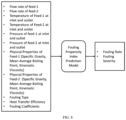
- FIG. 4 A schematic block diagram illustrating a thermal properties model is shown in FIG. 4 .
- the thermal properties model comprises of the data driven model.
- the model uses an inlet temperature measurement of feed as input to predict the thermal properties of the feeds of the heat exchanger.
- Thermal properties of feeds comprise of heat capacity, kinematic viscosity, specific gravity and so on.
- Thermal properties model can be distinct for each feed of the heat exchanger.
- the heat transfer efficiency model comprises of the first principle-based models and the data driven models.
- the heat transfer efficiency model may also comprise of a physics-based model that solves differential equations representing the flow, and heat transfer involved in the heat exchanger heat transfer process.
- the model uses the preprocessed operation data (real time sensor data for flow rates of feeds, temperature measurement of feeds), design data of heat exchangers (geometry, material thermo-physical properties), predicted thermal properties of feeds as input for prediction of outlet temperatures of feeds and heat transfer efficiency of the heat exchanger.
- the fouling type prediction model comprises either or combination of data driven models, knowledge-based models, and rule-based models.
- the model uses the preprocessed operation data (real time sensor data for flow rates of feeds, temperature measurement of feeds, pressure measurement of feeds), design data of heat exchangers (geometry, material thermo-physical properties), predicted thermal properties of feeds, thermal efficiency of the heat exchanger as input.
- This model predicts, the type of fouling heat exchanger undergoes in real time for the heat exchanger.
- the fouling type prediction model can be distinct for distinct heat exchanger in the heat exchanger network.
- the fouling parameter estimation model comprises either or combination of the data driven models, the knowledge-based models, and the rule-based models.
- the model uses the preprocessed operation data (real time sensor data for flow rates of feeds, temperature measurement of feeds, pressure measurement of feeds), design data of heat exchangers (geometry, material thermo-physical properties), predicted thermal properties of feeds, predicted fouling type, thermal efficiency of the heat exchanger as input.
- This model predicts, fouling coefficients for each heat exchanger of the heat exchanger network.
- the fouling coefficient for the heat exchanger comprises of fouling deposition coefficient, fouling suppression coefficient, fouling activation energy, ageing pre-exponential parameter, ageing activation energy.
- the predicted fouling coefficients are further used as input parameters for the fouling propensity index prediction model.
- the fouling parameter estimation model can be distinct for distinct heat exchanger in the heat exchanger network.
- the fouling propensity index prediction model comprises either or combination of first principle-based models, data driven models, knowledge-based models, and rule-based models.
- the model uses the preprocessed operation data (real time sensor data for flow rates of feeds, temperature measurement of feeds, pressure measurement of feeds), design data of heat exchangers (geometry, material thermo-physical properties), predicted thermal properties of feeds, predicted fouling type, predicted fouling coefficients and thermal efficiency of the heat exchanger as input. This model predicts, fouling rate and fouling severity for the heat exchanger.
- the fouling propensity index prediction model can be distinct for distinct heat exchanger in the heat exchanger network.
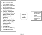
- the pressure drop model comprises either or combination of first principle-based models, data driven models, knowledge-based models, and rule-based models.
- the model uses the preprocessed operation data (real time sensor data for flow rates of feeds, temperature measurement of feeds), design data of heat exchangers (geometry, material thermo-physical properties), predicted thermal properties of feeds, predicted fouling type, predicted fouling coefficients and thermal efficiency of the heat exchanger as input. This model predicts, pressure drop for feeds of the heat exchanger.
- the pressure drop model can be distinct for distinct heat exchanger in the heat exchanger network.
- the system 100 comprises the observer unit 122.
- the observer unit 122 is configured to soft sense, a plurality of operating parameters, a plurality of fouling parameters and a fouling propensity index for each heat exchanger amongst the plurality of heat exchangers using models present in the observer unit 122.
- a flowchart 300 illustrating the steps involved in the observer unit 122 is shown in FIG. 3 .
- the observer unit 122 is also configured to interface with internal/external tools/models available in the system 100 for improved predictions.
- the system 100 comprises the analyzer unit 124.
- the analyzer unit 124 configured to detecting in real-time, a root cause of fouling by comparing the soft sensed plurality of operating parameters, the plurality of fouling parameters and the fouling propensity index using a set of predefined knowledge-based rules present in the analyzer unit 124.
- the analyzer unit 124 diagnoses operating regime changes, working fluid property variations and chemical/mechanical changes of fouling.
- the system 100 also comprises the predictor unit 126.
- the predictor unit 126 is configured to forecast, the fouling propensity index for a predefined forecast horizon for each heat exchanger amongst the plurality of heat exchangers using a plurality of forecast models present in the predictor unit 126.
- the plurality of forecast models is pre-built using the historically detected root cause of fouling and the soft sensed plurality of operating parameters and the plurality of fouling parameters.
- the fouling propensity index is indicative of the long term forecast for key fouling indicators of heat exchanger such as but not limited to fouling severity and fouling rate.
- the predictor unit 126 may also forecast pressure drop in heat exchanger and thermal performance of heat exchanger.
- the predictor unit 126 is also configured to find a remaining useful life (RUL) of each heat exchanger amongst the plurality of heat exchangers using the forecasted fouling propensity index for the predefined forecast horizon remaining useful operational life of the heat exchanger.
- RUL remaining useful life
- FIG. 10 is a flowchart 1000 illustrating steps involved in forecasting the fouling rate and the fouling severity over a predefined forecasting horizon t f and calculation of RUL of the heat exchanger.
- the preprocessed data from the data transformation unit 120 and the soft sensed data from the observer unit 122 are transformed appropriately. This transformation may comprise merging data, down sampling the data, appropriate scaling, removing outliers and cleaning the data.
- the operating parameters for the predefined forecast horizon t f are estimated.
- the plurality of operating parameters comprises of flow rates of feeds, inlet temperature of feeds for each heat exchanger in heat exchanger network.
- the thermal properties of the feeds are estimated using estimated plurality of operating parameters using the thermal properties model in the observer unit 122 for the predefined forecast horizon for each heat exchanger in heat exchanger network.
- the temperatures of feeds are estimated at an outlet of each heat exchanger using the estimated thermal properties, the estimated plurality of operating parameters and design data of heat exchanger using the heat transfer efficiency model in the observer unit 122 in the heat exchanger network.
- the fouling type is predicted using the estimated plurality of operating parameters, the estimated thermal properties, the estimated outlet temperatures using the fouling type prediction model of the observer unit 122 for each heat exchanger in heat exchanger network.
- fouling coefficients are predicted for future horizon using the estimated plurality of operating parameters, the estimated thermal properties, the estimated outlet temperatures, the estimated fouling type, and the estimated heat transfer efficiency using the fouling parameter estimation model for each heat exchanger in heat exchanger network.
- a fouling rate and the fouling severity is forecasted using the forecast model for the fouling severity index for each heat exchanger in heat exchanger network.
- Each heat exchanger in heat exchanger network may have distinct forecast model for fouling severity index.
- Input of the forecast model for fouling severity index comprise of the estimated data for the predefined forecast horizon and historical data of operation parameters, thermal properties of feeds, outlet temperatures of feeds of a heat exchanger in network and estimated data for forecast horizon and historical data of fouling type, fouling coefficients of all heat exchangers in network.
- the remaining useful life is calculated using the forecasted fouling rate and the fouling severity for the heat exchanger in heat exchanger network.
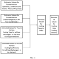
- FIG. 11 illustrates a block diagram of the forecast Model for calculating fouling severity index.
- Historical data and estimated values for future horizon for operation condition, thermo physical properties of feeds, outlet temperatures of feeds of a heat exchanger and historical data along with estimated values for future horizon for fouling type and fouling coefficients for all heat exchangers in network are used as input for the forecast model for the fouling severity index.
- Output of this model comprise of fouling severity and the fouling rate in the heat exchanger.
- Forecast model for the fouling severity index can be distinct for distinct heat exchangers in the network. Forecast of fouling rate and fouling severity is performed for each heat exchanger in the heat exchanger network.
- the system 100 comprises the recommender unit 128.
- the recommender 128 unit is configured to recommend, one or more of activity based on a set of forecasted parameters, operation constraint parameters and the RUL of each of the heat exchangers.
- the one or more activity comprises a cleaning and maintenance schedule of one or more of heat exchanger, or a set of operational changes in the one or more heat exchangers to increase the RUL.
- the recommendations are based on current and expected fouling conditions for optimizing efficiency, minimizing costs etc. Further, scheduling and maintenance advises are based on the forecast of fouling trends.
- the system 100 can also advise deployment of additional sensors at appropriate locations for increasing accuracy of fouling identification.
- FIG 12 is a flowchart 1200 illustrating the steps for generation of cleaning schedule and operation recommendation in the recommender unit 128.
- forecasted data for fouling severity and the fouling rate of each heat exchanger in the heat exchanger network is obtained from the prediction unit 126.
- an optimal cleaning schedule is generated using a cleaning schedule generation model using forecasted fouling severity and rate, predicted RLTL, design data, and maintenance history of each heat exchanger in the heat exchanger network and cost parameters data.
- Cost parameters data comprises of cost parameter for cleaning, maintenance planning, unavailability of the heat exchanger, and production loss due to unavailability of the heat exchanger.
- step 1206 type of cleaning to be performed for each heat exchanger is recommended to the operator based on the cleaning schedule generation model and the fouling severity data.
- Operation recommendation can be generated using knowledge-based model.
- operation recommendations are provided to the user based on the optimal cleaning schedule generated using a knowledge-based model. For example, based on optimal cleaning schedule system may suggest changes in feed flow rates in heat exchanger network to operator.
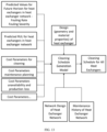
- FIG. 13 shows a block diagram of the recommender unit 128 using the cleaning schedule generation model.
- the cleaning schedule generation model comprises model based on either or combination of deep learning algorithm, reinforcement learning algorithm and optimization algorithm.
- Input for the cleaning schedule generation model comprise of forecasted fouling severity and rate for each heat exchanger in the heat exchanger network from the predictor unit 126, predicted RUL for each heat exchanger in the heat exchanger network form the predictor unit 126. design of heat exchangers in the heat exchanger network, network design of the heat exchanger network, maintenance history of heat exchanger network and cost parameters (cleaning, maintenance planning, unavailability, and production loss).
- FIG. 14 flow diagram of a method 1400 for identification and forecasting fouling of a plurality of heat exchangers in the refinery 102 is described in accordance with an example embodiment.
- the method 1400 depicted in the flow chart may be executed by a system, for example, the system, 100 of FIG. 1 .
- the system 100 may be embodied in the computing device as explained above.
- Operations of the flowchart, and combinations of operation in the flowchart may be implemented by various means, such as hardware, firmware, processor, circuitry and/or other device associated with execution of software including one or more computer program instructions.
- one or more of the procedures described in various embodiments may be embodied by computer program instructions.
- the computer program instructions, which embody the procedures, described in various embodiments may be stored by at least one memory device of a system and executed by at least one processor in the system. Any such computer program instructions may be loaded onto a computer or other programmable system (for example, hardware) to produce a machine, such that the resulting computer or other programmable system embody means for implementing the operations specified in the flowchart.
- the operations of the method 1400 are described with help of system 100. However, the operations of the method 1400 can be described and/or practiced by using any other system.
- a plurality of data related to the heat exchangers network is received from a plurality of data sources 134, wherein the network comprises the plurality of heat exchangers in the refinery 102.
- the received plurality of data is preprocessed and transformed.
- the plurality of operating parameters, the plurality of fouling parameters and the fouling propensity index is soft sensed for each heat exchanger amongst the plurality of heat exchangers using models present in the observer unit 122.
- a root cause of fouling is detected in real-time, by comparing the soft sensed plurality of operating parameters, the plurality of fouling parameters and the fouling propensity index using a set of predefined knowledge-based rules present in the analyzer unit 124.
- the fouling propensity index is forecasted for the predefined forecast horizon for each heat exchanger amongst the plurality of heat exchangers using a plurality of forecast models present in the predictor unit 126, wherein the plurality of forecast models is pre-built using the historically detected root cause of fouling and the soft sensed plurality of operating parameters and the plurality of fouling parameters.
- a remaining useful life (RLTL) of each heat exchanger amongst the plurality of heat exchangers is obtained using the forecasted fouling propensity index for the predefined forecast horizon.
- one or more of activities is recommended based on a set of parameters and the RUL of each of the heat exchangers, wherein the one or more activities comprises: a cleaning and maintenance schedule of one or more of heat exchanger, or a set of operational changes in the one or more heat exchangers to increase the RUL.
- the system 100 comprises the simulator unit 130.
- the simulator unit 130 is configured to simulate and understand the impact of 'what if' and 'if-what' scenarios for heat exchanger for e.g. refinery operator can forecast the fouling characteristics for different types of crude oil blends.
- the system 100 comprises the model update unit 132.
- the model update unit 132 enables automatic update of models if performance of the models is below a set threshold.
- the plurality of units used in the system comprises of specific models to carry out the intended tasks. This unit assist in calibrating existing models for prediction of fouling and other parameters with respect to the current performance of the heat exchangers. This may also comprise of tools for adapting a model built for a specific heat exchanger to another heat exchanger in the train or in other refinery.
- the plurality of units can work in online or offline mode as per the requirement. Some of the units may operate online in the background or some may work online in real-time.
- This system 100 can be applied to heat exchangers used in oil refinery as well as any other heat exchangers experiencing similar fouling, for example, heat exchangers in pre-heat train of refinery, transfer line exchangers in refinery.
- the system 100 may also include optimization solvers and reinforcement learning techniques for optimal control.
- the models could in turn interface with external models/tools, may receive inputs/outputs and may iterate over them.
- the plurality of units is supported by an interactive user interface that can be used to provide external inputs, receive outputs/recommendations, visualizations of analytics.
- the embodiments of present disclosure herein address unresolved problem of costs and effort involved in the maintenance of heat exchangers in the refinery.
- the embodiment thus provides a method and system for identification and forecasting fouling of a plurality of heat exchangers in a refinery
- the hardware device can be any kind of device which can be programmed including e.g. any kind of computer like a server or a personal computer, or the like, or any combination thereof.
- the device may also include means which could be e.g. hardware means like e.g. an application-specific integrated circuit (ASIC), a field-programmable gate array (FPGA), or a combination of hardware and software means, e.g.
- ASIC application-specific integrated circuit
- FPGA field-programmable gate array
- the means can include both hardware means and software means.
- the method embodiments described herein could be implemented in hardware and software.
- the device may also include software means.
- the embodiments may be implemented on different hardware devices, e.g. using a plurality of CPUs.
- the embodiments herein can comprise hardware and software elements.
- the embodiments that are implemented in software include but are not limited to, firmware, resident software, microcode, etc.
- the functions performed by various components described herein may be implemented in other components or combinations of other components.
- a computer-usable or computer readable medium can be any apparatus that can comprise, store, communicate, propagate, or transport the program for use by or in connection with the instruction execution system, apparatus, or device.
- a computer-readable storage medium refers to any type of physical memory on which information or data readable by a processor may be stored.
- a computer-readable storage medium may store instructions for execution by one or more processors, including instructions for causing the processor(s) to perform steps or stages consistent with the embodiments described herein.
- the term "computer-readable medium” should be understood to include tangible items and exclude carrier waves and transient signals, i.e., be non-transitory. Examples include random access memory (RAM), read-only memory (ROM), volatile memory, nonvolatile memory, hard drives, CD ROMs, DVDs, flash drives, disks, and any other known physical storage media.
Landscapes
- Engineering & Computer Science (AREA)
- Physics & Mathematics (AREA)
- Theoretical Computer Science (AREA)
- General Physics & Mathematics (AREA)
- General Engineering & Computer Science (AREA)
- Evolutionary Computation (AREA)
- Software Systems (AREA)
- Artificial Intelligence (AREA)
- Data Mining & Analysis (AREA)
- Automation & Control Theory (AREA)
- Computing Systems (AREA)
- Mathematical Physics (AREA)
- Chemical & Material Sciences (AREA)
- Computer Vision & Pattern Recognition (AREA)
- Medical Informatics (AREA)
- Geometry (AREA)
- Computational Linguistics (AREA)
- Computer Hardware Design (AREA)
- Oil, Petroleum & Natural Gas (AREA)
- Thermal Sciences (AREA)
- Mechanical Engineering (AREA)
- Organic Chemistry (AREA)
- General Chemical & Material Sciences (AREA)
- Chemical Kinetics & Catalysis (AREA)
- Life Sciences & Earth Sciences (AREA)
- Bioinformatics & Cheminformatics (AREA)
- Bioinformatics & Computational Biology (AREA)
- Evolutionary Biology (AREA)
- Testing And Monitoring For Control Systems (AREA)
Claims (11)
- Procédé (1400), mis en oeuvre par processeur, d'identification et de prévision d'un encrassement d'une pluralité d'échangeurs de chaleur dans une raffinerie, le procédé comprenant les étapes ci-dessous consistant à :recevoir, par l'intermédiaire d'un ou plusieurs processeurs matériels, une pluralité de données connexes à un réseau d'échangeurs de chaleur, en provenance d'une pluralité de sources de données, dans lequel le réseau d'échangeurs de chaleur comprend une pluralité d'échangeurs de chaleur dans la raffinerie (1402) ;prétraiter, par l'intermédiaire dudit un ou desdits plusieurs processeurs matériels, la pluralité de données reçue, au moyen d'une pluralité de modèles préconstruits présents dans une unité de transformation de données (1404) ; le procédé étant caractérisé par les étapes ci-dessous consistant à :détecter virtuellement, par l'intermédiaire dudit un ou desdits plusieurs processeurs matériels, une pluralité de paramètres de fonctionnement, une pluralité de paramètres d'encrassement et un indice de propension à l'encrassement pour chaque échangeur de chaleur parmi la pluralité d'échangeurs de chaleur, au moyen de modèles préconstruits présents dans une unité d'observation (1406), dans lequel la pluralité de paramètres de fonctionnement, la pluralité de paramètres d'encrassement et l'indice de propension à l'encrassement comprennent une température de sortie de chaque alimentation des échangeurs de chaleur, une pression de sortie de chaque alimentation des échangeurs de chaleur, une efficacité de transfert de chaleur des échangeurs de chaleur, un type d'encrassement comprenant un encrassement organique et un encrassement inorganique, des coefficients d'encrassement, un taux d'encrassement et une gravité d'encrassement des échangeurs de chaleur ;détecter en temps réel, par l'intermédiaire dudit un ou desdits plusieurs processeurs matériels, une cause fondamentale de l'encrassement, en comparant la pluralité de paramètres de fonctionnement, la pluralité de paramètres d'encrassement et l'indice de propension à l'encrassement détectés virtuellement, au moyen d'un ensemble de règles prédéfinies présentes dans une unité d'analyse (1408) ;prévoir, par l'intermédiaire dudit un ou desdits plusieurs processeurs matériels, un ensemble de paramètres prévus et un indice de propension à l'encrassement prévu, pour un horizon de prévision prédéfini, pour chaque échangeur de chaleur parmi la pluralité d'échangeurs de chaleur, en faisant appel à une pluralité de modèles de prévision préconstruits présents dans une unité de prédiction (1410), dans laquelle les modèles de la pluralité de modèles de prévision préconstruits sont construits en utilisant une cause fondamentale d'encrassement détectée historiquement et la pluralité de paramètres de fonctionnement et la pluralité de paramètres d'encrassement détectés virtuellement ;déterminer, par l'intermédiaire dudit un ou desdits plusieurs processeurs matériels, une durée de vie utile restante, RUL, de chaque échangeur de chaleur parmi la pluralité d'échangeurs de chaleur, au moyen de l'indice de propension à l'encrassement prévu pour l'horizon de prévision prédéfini (1412) ; etrecommander, par l'intermédiaire dudit un ou desdits plusieurs processeurs matériels, une ou plusieurs activités, sur la base de l'ensemble de paramètres prévus, de l'indice de propension à l'encrassement prévu, de paramètres de contrainte de fonctionnement, de la durée RUL de chacun des échangeurs de chaleur, d'un coût impliqué dans le nettoyage et la maintenance d'un ou plusieurs des échangeurs de chaleur, et d'un historique de maintenance du réseau d'échangeurs de chaleur, dans lequel les paramètres de contrainte de fonctionnement comprennent des données de paramètres de coût, une spécification de conception des échangeurs de chaleur, et une spécification de conception du réseau d'échangeurs de chaleur, et dans lequel ladite une ou lesdites plusieurs activités comprennent :une planification de nettoyage et de maintenance d'un ou plusieurs des échangeurs de chaleur ; ouun ensemble de modifications opérationnelles dans ledit un ou lesdits plusieurs échangeurs de chaleur pour augmenter la durée RUL (1414).
- Procédé selon la revendication 1, comprenant en outre l'étape consistant à activer une mise à jour automatique de la pluralité de modèles préconstruits et de la pluralité de modèles de prévision préconstruits si une performance de la pluralité de modèles préconstruits et de la pluralité de modèles de prévision préconstruits est inférieure à un seuil défini.
- Procédé selon la revendication 1, dans lequel la pluralité de paramètres de fonctionnement comprend une température d'alimentation, une pression d'alimentation, un débit d'alimentation et des propriétés thermo-physiques d'alimentations pour la pluralité d'échangeurs de chaleur dans le réseau d'échangeurs de chaleur.
- Procédé selon la revendication 1, dans lequel la pluralité de données comprend :des paramètres de fonctionnement en temps réel pour la pluralité d'échangeurs de chaleur du réseau d'échangeurs de chaleur, dans lesquels les paramètres de fonctionnement en temps réel comprennent une mesure de température d'alimentations, une mesure de pression d'alimentations, une mesure de débit d'alimentations ;des propriétés thermo-physiques des alimentations ;des données de conception pour la pluralité d'échangeurs de chaleur du réseau d'échangeurs de chaleur, dans lesquelles les données de conception comprennent des mesures géométriques de la pluralité d'échangeurs de chaleur, des propriétés physiques de la pluralité d'échangeurs de chaleur et des propriétés thermiques de la pluralité d'échangeurs de chaleur ;des données de spécification de conception du réseau d'échangeurs de chaleur ; etun historique de maintenance et de nettoyage de la pluralité d'échangeurs de chaleur du réseau d'échangeurs de chaleur.
- Procédé selon la revendication 1, dans lequel la pluralité de sources de données comprend un système de commande réparti, DCS, et un ou plusieurs des systèmes parmi un système de télésurveillance et acquisition de données, SCADA, un système de gestion intégré, ERP, un historien de données, un système de gestion de l'information du laboratoire, LIMS, un système d'exécution de la fabrication, MES, un système de gestion des opérations de fabrication, MOM, des bases de données, une pluralité de capteurs, des sources externes, des systèmes d'entrée manuelle et d'autres systèmes numériques dans une usine.
- Procédé selon la revendication 1, dans lequel le prétraitement des données comprend l'identification et la suppression de valeurs aberrantes, l'imputation de données manquantes, la synchronisation et l'intégration d'une pluralité de variables provenant de la pluralité de sources de données, et la transformation de la pluralité de données en une pluralité de formes, de tailles et de fréquences sur la base d'un horizon de prévision prédéfini.
- Procédé selon la revendication 1, dans lequel la planification de nettoyage et de maintenance est générée par un modèle de génération de planification de nettoyage basé sur l'un ou l'autre ou la combinaison d'un algorithme d'apprentissage profond, d'un algorithme d'apprentissage par renforcement et d'un algorithme d'optimisation.
- Procédé selon la revendication 1, dans lequel l'ensemble de paramètres prévus comprend une prévision de coefficients d'encrassement, de gravité d'encrassement, de taux d'encrassement et de type d'encrassement.
- Procédé selon la revendication 1, dans lequel la cause fondamentale de l'encrassement comprend un changement dans l'alimentation, un changement dans le régime de fonctionnement et un changement dans les conditions environnementales.
- Procédé selon la revendication 1, dans lequel les modèles dans l'unité de transformation de données, l'unité d'observation et l'unité de prédiction comprennent des modèles pilotés par les données, des modèles basés sur des principes premiers, des modèles basés sur les connaissances et une combinaison de ceux-ci.
- Système (100) d'identification et de prévision d'un encrassement d'une pluralité d'échangeurs de chaleur dans une raffinerie (102), le système comprenant :une interface entrée/sortie (110) ;un ou plusieurs processeurs matériels (114) ;une mémoire (116), en communication avec ledit un ou lesdits plusieurs processeurs matériels, dans lesquels ledit un ou lesdits plusieurs processeurs matériels sont configurés de manière à exécuter des instructions programmées stockées dans la mémoire, en vue de mettre en oeuvre les étapes ci-dessous consistant à :recevoir une pluralité de données connexes à un réseau d'échangeurs de chaleur, en provenance d'une pluralité de sources de données, dans lequel le réseau d'échangeurs de chaleur comprend une pluralité d'échangeurs de chaleur dans la raffinerie ;prétraiter la pluralité de données reçue, au moyen d'une pluralité de modèles préconstruits présents dans une unité de transformation de données (120) ; le système étant caractérisé en ce que ledit un ou lesdits plusieurs processeurs matériels sont en outre configurés de manière à mettre en oeuvre les étapes ci-dessous consistant à :détecter virtuellement une pluralité de paramètres de fonctionnement, une pluralité de paramètres d'encrassement et un indice de propension à l'encrassement pour chaque échangeur de chaleur parmi la pluralité d'échangeurs de chaleur, au moyen de modèles préconstruits présents dans une unité d'observation (122), dans lequel la pluralité de paramètres de fonctionnement, la pluralité de paramètres d'encrassement et l'indice de propension à l'encrassement comprennent une température de sortie de chaque alimentation des échangeurs de chaleur, une pression de sortie de chaque alimentation des échangeurs de chaleur, une efficacité de transfert de chaleur des échangeurs de chaleur, un type d'encrassement comprenant un encrassement organique et un encrassement inorganique, des coefficients d'encrassement, un taux d'encrassement et une gravité d'encrassement des échangeurs de chaleur ;détecter en temps réel une cause fondamentale de l'encrassement, en comparant la pluralité de paramètres de fonctionnement, la pluralité de paramètres d'encrassement et l'indice de propension à l'encrassement détectés virtuellement, au moyen d'un ensemble de règles prédéfinies présentes dans une unité d'analyse (124) ;prévoir un ensemble de paramètres prévus et un indice de propension à l'encrassement prévu, pour un horizon de prévision prédéfini, pour chaque échangeur de chaleur parmi la pluralité d'échangeurs de chaleur, en faisant appel à une pluralité de modèles de prévision préconstruits présents dans une unité de prédiction (126), dans laquelle les modèles de la pluralité de modèles de prévision préconstruits sont construits en utilisant une cause fondamentale d'encrassement détectée historiquement et la pluralité de paramètres de fonctionnement et la pluralité de paramètres d'encrassement détectés virtuellement ;déterminer une durée de vie utile restante, RUL, de chaque échangeur de chaleur parmi la pluralité d'échangeurs de chaleur, au moyen de l'indice de propension à l'encrassement prévu pour l'horizon de prévision prédéfini ; etrecommander une ou plusieurs activités, sur la base de l'ensemble de paramètres prévus, de l'indice de propension à l'encrassement prévu, de paramètres de contrainte de fonctionnement, de la durée RUL de chacun des échangeurs de chaleur, d'un coût impliqué dans le nettoyage et la maintenance d'un ou plusieurs des échangeurs de chaleur, et d'un historique de maintenance du réseau d'échangeurs de chaleur, dans lequel les paramètres de contrainte de fonctionnement comprennent des données de paramètres de coût, une spécification de conception des échangeurs de chaleur, et une spécification de conception du réseau d'échangeurs de chaleur, et dans lequel ladite une ou lesdites plusieurs activités comprennent :une planification de nettoyage et de maintenance d'un ou plusieurs des échangeurs de chaleur ; ouun ensemble de modifications opérationnelles dans ledit un ou lesdits plusieurs échangeurs de chaleur pour augmenter la durée RUL.
Applications Claiming Priority (1)
| Application Number | Priority Date | Filing Date | Title |
|---|---|---|---|
| IN202021040367 | 2020-09-17 |
Publications (3)
| Publication Number | Publication Date |
|---|---|
| EP3971671A1 EP3971671A1 (fr) | 2022-03-23 |
| EP3971671B1 true EP3971671B1 (fr) | 2023-11-01 |
| EP3971671C0 EP3971671C0 (fr) | 2023-11-01 |
Family
ID=77801549
Family Applications (1)
| Application Number | Title | Priority Date | Filing Date |
|---|---|---|---|
| EP21197077.7A Active EP3971671B1 (fr) | 2020-09-17 | 2021-09-16 | Système et procédé d'identification et de prévision de l'encrassement des échangeurs de chaleur dans une raffinerie |
Country Status (2)
| Country | Link |
|---|---|
| US (1) | US12547800B2 (fr) |
| EP (1) | EP3971671B1 (fr) |
Families Citing this family (6)
| Publication number | Priority date | Publication date | Assignee | Title |
|---|---|---|---|---|
| EP4033321B1 (fr) * | 2021-01-22 | 2024-07-03 | Tata Consultancy Services Limited | Système et procédé de surveillance de performance et de santé pour optimiser le fonctionnement d'un broyeur pulvérisateur |
| US20230146661A1 (en) * | 2021-11-08 | 2023-05-11 | King Fahd University Of Petroleum And Minerals | System and method of determining fouling location of shell and tube heat exchanger |
| WO2024167749A1 (fr) * | 2023-02-09 | 2024-08-15 | Chevron U.S.A. Inc. | Planification de la maintenance des échangeurs de chaleur par analyse prédictive |
| CN119783514B (zh) * | 2024-12-14 | 2025-09-09 | 西安热工研究院有限公司 | 一种燃煤机组孪生机理模型锅炉参数自校正方法及装置 |
| CN120410515B (zh) * | 2025-07-03 | 2025-09-12 | 利兴凯(北京)能源系统技术有限公司 | 电厂锅炉水冷壁结垢智能预测与清洗方法及系统 |
| CN121206964A (zh) * | 2025-11-26 | 2025-12-26 | 四川凌耘建科技有限公司 | 一种管壳式换热器的ai-pi协同节能控制方法及换热器 |
Family Cites Families (8)
| Publication number | Priority date | Publication date | Assignee | Title |
|---|---|---|---|---|
| US7455099B2 (en) | 2003-12-19 | 2008-11-25 | General Electric Company | Heat exchanger performance monitoring and analysis method and system |
| EP3165867A1 (fr) * | 2015-11-06 | 2017-05-10 | Honeywell spol s.r.o. | Capteur inférentiel de paramètres d'échangeur de chaleur interne |
| US10328408B2 (en) | 2017-03-28 | 2019-06-25 | Uop Llc | Detecting and correcting fouling in heat exchangers |
| JP7344201B2 (ja) * | 2017-11-10 | 2023-09-13 | エコラブ ユーエスエイ インク | 冷却水監視制御システム |
| CA3003072C (fr) * | 2018-04-30 | 2021-02-09 | Suncor Energy Inc. | Systemes et procedes destines a predire l'encrassement des tubes dans un appareil a combustion et pour utiliser les predictions d'encrassement des tubes |
| US11480517B2 (en) * | 2019-08-08 | 2022-10-25 | Saudi Arabian Oil Company | Heat exchanger fouling determination using thermography combined with machine learning methods |
| WO2021070201A2 (fr) | 2019-10-09 | 2021-04-15 | Tata Consultancy Services Limited | Procédé et système de surveillance et de prévision en temps réel de l'encrassement d'un équipement de préchauffeur d'air |
| US11732967B2 (en) * | 2019-12-11 | 2023-08-22 | Baltimore Aircoil Company, Inc. | Heat exchanger system with machine-learning based optimization |
-
2021
- 2021-09-16 EP EP21197077.7A patent/EP3971671B1/fr active Active
- 2021-09-16 US US17/476,746 patent/US12547800B2/en active Active
Also Published As
| Publication number | Publication date |
|---|---|
| EP3971671A1 (fr) | 2022-03-23 |
| EP3971671C0 (fr) | 2023-11-01 |
| US12547800B2 (en) | 2026-02-10 |
| US20220083716A1 (en) | 2022-03-17 |
Similar Documents
| Publication | Publication Date | Title |
|---|---|---|
| EP3971671B1 (fr) | Système et procédé d'identification et de prévision de l'encrassement des échangeurs de chaleur dans une raffinerie | |
| JP7333473B2 (ja) | 空気予熱機器の汚染をリアルタイムで監視及び予測する方法及びシステム | |
| US11507898B2 (en) | System and method for dynamic multi-objective optimization of machine selection, integration and utilization | |
| EP4033321A1 (fr) | Système et procédé de surveillance de performance et de santé pour optimiser le fonctionnement d'un broyeur pulvérisateur | |
| US11232368B2 (en) | System for predicting equipment failure events and optimizing manufacturing operations | |
| US8417360B2 (en) | System and method for dynamic multi-objective optimization of machine selection, integration and utilization | |
| US9729639B2 (en) | System and method for dynamic multi-objective optimization of machine selection, integration and utilization | |
| US20180268333A1 (en) | Intelligent Decision Synchronization in Real Time for both Discrete and Continuous Process Industries | |
| US20090210081A1 (en) | System and method for dynamic multi-objective optimization of machine selection, integration and utilization | |
| EP2172887A2 (fr) | Système et procédé pour l'optimisation dynamique multi-objectifs de sélection, intégration et utilisation de machines | |
| US20090204237A1 (en) | System and method for dynamic multi-objective optimization of machine selection, integration and utilization | |
| Yıldız et al. | Integrating preventive and predictive maintenance policies with system dynamics: A decision table approach | |
| US20240319718A1 (en) | System and method for intelligent scheduling of manufacturing jobs | |
| CN118915591A (zh) | 一种数字化工厂监测数据挖掘方法及系统 | |
| Emma | AI-Driven Predictive Maintenance for Smart Manufacturing and Industry 4.0 | |
| Sharma et al. | Industry 4.0 technologies for smart manufacturing: a systematic review of machine learning methods for predictive maintenance | |
| Elvis et al. | Developing a predictive maintenance model using IoT and machine learning | |
| Koritala et al. | Automated Engine Management and Monitoring with AI | |
| Yesodha et al. | IoT-Driven Real-Time Data Collection and Analysis for Lean Manufacturing | |
| Emroozi et al. | A System Dynamics–Optimization Framework for Human-Error-Aware Preventive Maintenance Planning | |
| Emmanuel | Artificial Intelligence in Predictive Maintenance for Industry | |
| US12619227B2 (en) | Method and system for causal inference and root cause identification in industrial processes | |
| Karri | Predictive Maintenance and Health Monitoring | |
| Gasior et al. | Machine Learning-Based Recommender System for Tweeting Factory in Industry 5.0 Paradigm | |
| Hossini | Adaptive predictive maintenance strategies for smart buildings |
Legal Events
| Date | Code | Title | Description |
|---|---|---|---|
| PUAI | Public reference made under article 153(3) epc to a published international application that has entered the european phase |
Free format text: ORIGINAL CODE: 0009012 |
|
| STAA | Information on the status of an ep patent application or granted ep patent |
Free format text: STATUS: THE APPLICATION HAS BEEN PUBLISHED |
|
| AK | Designated contracting states |
Kind code of ref document: A1 Designated state(s): AL AT BE BG CH CY CZ DE DK EE ES FI FR GB GR HR HU IE IS IT LI LT LU LV MC MK MT NL NO PL PT RO RS SE SI SK SM TR |
|
| STAA | Information on the status of an ep patent application or granted ep patent |
Free format text: STATUS: REQUEST FOR EXAMINATION WAS MADE |
|
| 17P | Request for examination filed |
Effective date: 20220804 |
|
| RBV | Designated contracting states (corrected) |
Designated state(s): AL AT BE BG CH CY CZ DE DK EE ES FI FR GB GR HR HU IE IS IT LI LT LU LV MC MK MT NL NO PL PT RO RS SE SI SK SM TR |
|
| GRAP | Despatch of communication of intention to grant a patent |
Free format text: ORIGINAL CODE: EPIDOSNIGR1 |
|
| STAA | Information on the status of an ep patent application or granted ep patent |
Free format text: STATUS: GRANT OF PATENT IS INTENDED |
|
| RIC1 | Information provided on ipc code assigned before grant |
Ipc: F28F 19/00 20060101ALI20230324BHEP Ipc: G05B 23/02 20060101AFI20230324BHEP |
|
| INTG | Intention to grant announced |
Effective date: 20230414 |
|
| GRAS | Grant fee paid |
Free format text: ORIGINAL CODE: EPIDOSNIGR3 |
|
| GRAA | (expected) grant |
Free format text: ORIGINAL CODE: 0009210 |
|
| STAA | Information on the status of an ep patent application or granted ep patent |
Free format text: STATUS: THE PATENT HAS BEEN GRANTED |
|
| AK | Designated contracting states |
Kind code of ref document: B1 Designated state(s): AL AT BE BG CH CY CZ DE DK EE ES FI FR GB GR HR HU IE IS IT LI LT LU LV MC MK MT NL NO PL PT RO RS SE SI SK SM TR |
|
| REG | Reference to a national code |
Ref country code: GB Ref legal event code: FG4D |
|
| REG | Reference to a national code |
Ref country code: CH Ref legal event code: EP |
|
| REG | Reference to a national code |
Ref country code: IE Ref legal event code: FG4D |
|
| REG | Reference to a national code |
Ref country code: DE Ref legal event code: R096 Ref document number: 602021006385 Country of ref document: DE |
|
| U01 | Request for unitary effect filed |
Effective date: 20231101 |
|
| U07 | Unitary effect registered |
Designated state(s): AT BE BG DE DK EE FI FR IT LT LU LV MT NL PT SE SI Effective date: 20231108 |
|
| PG25 | Lapsed in a contracting state [announced via postgrant information from national office to epo] |
Ref country code: GR Free format text: LAPSE BECAUSE OF FAILURE TO SUBMIT A TRANSLATION OF THE DESCRIPTION OR TO PAY THE FEE WITHIN THE PRESCRIBED TIME-LIMIT Effective date: 20240202 |
|
| PG25 | Lapsed in a contracting state [announced via postgrant information from national office to epo] |
Ref country code: IS Free format text: LAPSE BECAUSE OF FAILURE TO SUBMIT A TRANSLATION OF THE DESCRIPTION OR TO PAY THE FEE WITHIN THE PRESCRIBED TIME-LIMIT Effective date: 20240301 |
|
| PG25 | Lapsed in a contracting state [announced via postgrant information from national office to epo] |
Ref country code: ES Free format text: LAPSE BECAUSE OF FAILURE TO SUBMIT A TRANSLATION OF THE DESCRIPTION OR TO PAY THE FEE WITHIN THE PRESCRIBED TIME-LIMIT Effective date: 20231101 |
|
| PG25 | Lapsed in a contracting state [announced via postgrant information from national office to epo] |
Ref country code: IS Free format text: LAPSE BECAUSE OF FAILURE TO SUBMIT A TRANSLATION OF THE DESCRIPTION OR TO PAY THE FEE WITHIN THE PRESCRIBED TIME-LIMIT Effective date: 20240301 Ref country code: GR Free format text: LAPSE BECAUSE OF FAILURE TO SUBMIT A TRANSLATION OF THE DESCRIPTION OR TO PAY THE FEE WITHIN THE PRESCRIBED TIME-LIMIT Effective date: 20240202 Ref country code: ES Free format text: LAPSE BECAUSE OF FAILURE TO SUBMIT A TRANSLATION OF THE DESCRIPTION OR TO PAY THE FEE WITHIN THE PRESCRIBED TIME-LIMIT Effective date: 20231101 |
|
| PG25 | Lapsed in a contracting state [announced via postgrant information from national office to epo] |
Ref country code: RS Free format text: LAPSE BECAUSE OF FAILURE TO SUBMIT A TRANSLATION OF THE DESCRIPTION OR TO PAY THE FEE WITHIN THE PRESCRIBED TIME-LIMIT Effective date: 20231101 Ref country code: PL Free format text: LAPSE BECAUSE OF FAILURE TO SUBMIT A TRANSLATION OF THE DESCRIPTION OR TO PAY THE FEE WITHIN THE PRESCRIBED TIME-LIMIT Effective date: 20231101 Ref country code: NO Free format text: LAPSE BECAUSE OF FAILURE TO SUBMIT A TRANSLATION OF THE DESCRIPTION OR TO PAY THE FEE WITHIN THE PRESCRIBED TIME-LIMIT Effective date: 20240201 Ref country code: HR Free format text: LAPSE BECAUSE OF FAILURE TO SUBMIT A TRANSLATION OF THE DESCRIPTION OR TO PAY THE FEE WITHIN THE PRESCRIBED TIME-LIMIT Effective date: 20231101 |
|
| PG25 | Lapsed in a contracting state [announced via postgrant information from national office to epo] |
Ref country code: CZ Free format text: LAPSE BECAUSE OF FAILURE TO SUBMIT A TRANSLATION OF THE DESCRIPTION OR TO PAY THE FEE WITHIN THE PRESCRIBED TIME-LIMIT Effective date: 20231101 |
|
| PG25 | Lapsed in a contracting state [announced via postgrant information from national office to epo] |
Ref country code: SK Free format text: LAPSE BECAUSE OF FAILURE TO SUBMIT A TRANSLATION OF THE DESCRIPTION OR TO PAY THE FEE WITHIN THE PRESCRIBED TIME-LIMIT Effective date: 20231101 |
|
| PG25 | Lapsed in a contracting state [announced via postgrant information from national office to epo] |
Ref country code: SM Free format text: LAPSE BECAUSE OF FAILURE TO SUBMIT A TRANSLATION OF THE DESCRIPTION OR TO PAY THE FEE WITHIN THE PRESCRIBED TIME-LIMIT Effective date: 20231101 Ref country code: SK Free format text: LAPSE BECAUSE OF FAILURE TO SUBMIT A TRANSLATION OF THE DESCRIPTION OR TO PAY THE FEE WITHIN THE PRESCRIBED TIME-LIMIT Effective date: 20231101 Ref country code: CZ Free format text: LAPSE BECAUSE OF FAILURE TO SUBMIT A TRANSLATION OF THE DESCRIPTION OR TO PAY THE FEE WITHIN THE PRESCRIBED TIME-LIMIT Effective date: 20231101 |
|
| REG | Reference to a national code |
Ref country code: DE Ref legal event code: R097 Ref document number: 602021006385 Country of ref document: DE |
|
| PLBE | No opposition filed within time limit |
Free format text: ORIGINAL CODE: 0009261 |
|
| STAA | Information on the status of an ep patent application or granted ep patent |
Free format text: STATUS: NO OPPOSITION FILED WITHIN TIME LIMIT |
|
| 26N | No opposition filed |
Effective date: 20240802 |
|
| U20 | Renewal fee for the european patent with unitary effect paid |
Year of fee payment: 4 Effective date: 20240926 |
|
| PG25 | Lapsed in a contracting state [announced via postgrant information from national office to epo] |
Ref country code: MC Free format text: LAPSE BECAUSE OF FAILURE TO SUBMIT A TRANSLATION OF THE DESCRIPTION OR TO PAY THE FEE WITHIN THE PRESCRIBED TIME-LIMIT Effective date: 20231101 |
|
| PG25 | Lapsed in a contracting state [announced via postgrant information from national office to epo] |
Ref country code: IE Free format text: LAPSE BECAUSE OF NON-PAYMENT OF DUE FEES Effective date: 20240916 |
|
| REG | Reference to a national code |
Ref country code: CH Ref legal event code: U11 Free format text: ST27 STATUS EVENT CODE: U-0-0-U10-U11 (AS PROVIDED BY THE NATIONAL OFFICE) Effective date: 20251001 |
|
| PGFP | Annual fee paid to national office [announced via postgrant information from national office to epo] |
Ref country code: GB Payment date: 20250923 Year of fee payment: 5 |
|
| U20 | Renewal fee for the european patent with unitary effect paid |
Year of fee payment: 5 Effective date: 20250925 |
|
| PG25 | Lapsed in a contracting state [announced via postgrant information from national office to epo] |
Ref country code: RO Free format text: LAPSE BECAUSE OF FAILURE TO SUBMIT A TRANSLATION OF THE DESCRIPTION OR TO PAY THE FEE WITHIN THE PRESCRIBED TIME-LIMIT Effective date: 20231101 |
|
| PGFP | Annual fee paid to national office [announced via postgrant information from national office to epo] |
Ref country code: CH Payment date: 20251001 Year of fee payment: 5 |
|
| PG25 | Lapsed in a contracting state [announced via postgrant information from national office to epo] |
Ref country code: CY Free format text: LAPSE BECAUSE OF FAILURE TO SUBMIT A TRANSLATION OF THE DESCRIPTION OR TO PAY THE FEE WITHIN THE PRESCRIBED TIME-LIMIT; INVALID AB INITIO Effective date: 20210916 |
|
| PG25 | Lapsed in a contracting state [announced via postgrant information from national office to epo] |
Ref country code: HU Free format text: LAPSE BECAUSE OF FAILURE TO SUBMIT A TRANSLATION OF THE DESCRIPTION OR TO PAY THE FEE WITHIN THE PRESCRIBED TIME-LIMIT; INVALID AB INITIO Effective date: 20210916 |