EP3972049A1 - Réseau d'antennes à double polarisation - Google Patents
Réseau d'antennes à double polarisation Download PDFInfo
- Publication number
- EP3972049A1 EP3972049A1 EP20197063.9A EP20197063A EP3972049A1 EP 3972049 A1 EP3972049 A1 EP 3972049A1 EP 20197063 A EP20197063 A EP 20197063A EP 3972049 A1 EP3972049 A1 EP 3972049A1
- Authority
- EP
- European Patent Office
- Prior art keywords
- radiators
- clusters
- group
- separately fed
- cluster
- Prior art date
- Legal status (The legal status is an assumption and is not a legal conclusion. Google has not performed a legal analysis and makes no representation as to the accuracy of the status listed.)
- Withdrawn
Links
- 230000005684 electric field Effects 0.000 claims abstract description 62
- 230000010287 polarization Effects 0.000 claims description 26
- 239000000758 substrate Substances 0.000 claims description 8
- 230000009977 dual effect Effects 0.000 claims description 2
- 230000001413 cellular effect Effects 0.000 description 2
- 230000008878 coupling Effects 0.000 description 2
- 238000010168 coupling process Methods 0.000 description 2
- 238000005859 coupling reaction Methods 0.000 description 2
- 239000003989 dielectric material Substances 0.000 description 2
- 238000001914 filtration Methods 0.000 description 2
- 230000000007 visual effect Effects 0.000 description 2
- 229910052782 aluminium Inorganic materials 0.000 description 1
- XAGFODPZIPBFFR-UHFFFAOYSA-N aluminium Chemical compound [Al] XAGFODPZIPBFFR-UHFFFAOYSA-N 0.000 description 1
- 238000003491 array Methods 0.000 description 1
- 230000003190 augmentative effect Effects 0.000 description 1
- 230000000694 effects Effects 0.000 description 1
- 230000001404 mediated effect Effects 0.000 description 1
- 229910052751 metal Inorganic materials 0.000 description 1
- 239000002184 metal Substances 0.000 description 1
- 230000004048 modification Effects 0.000 description 1
- 238000012986 modification Methods 0.000 description 1
- 230000003287 optical effect Effects 0.000 description 1
- 238000009877 rendering Methods 0.000 description 1
Images





Classifications
-
- H—ELECTRICITY
- H01—ELECTRIC ELEMENTS
- H01Q—ANTENNAS, i.e. RADIO AERIALS
- H01Q21/00—Antenna arrays or systems
- H01Q21/24—Combinations of antenna units polarised in different directions for transmitting or receiving circularly and elliptically polarised waves or waves linearly polarised in any direction
-
- H—ELECTRICITY
- H01—ELECTRIC ELEMENTS
- H01Q—ANTENNAS, i.e. RADIO AERIALS
- H01Q1/00—Details of, or arrangements associated with, antennas
- H01Q1/12—Supports; Mounting means
- H01Q1/22—Supports; Mounting means by structural association with other equipment or articles
- H01Q1/24—Supports; Mounting means by structural association with other equipment or articles with receiving set
- H01Q1/241—Supports; Mounting means by structural association with other equipment or articles with receiving set used in mobile communications, e.g. GSM
- H01Q1/246—Supports; Mounting means by structural association with other equipment or articles with receiving set used in mobile communications, e.g. GSM specially adapted for base stations
-
- H—ELECTRICITY
- H01—ELECTRIC ELEMENTS
- H01Q—ANTENNAS, i.e. RADIO AERIALS
- H01Q19/00—Combinations of primary active antenna elements and units with secondary devices, e.g. with quasi-optical devices, for giving the antenna a desired directional characteristic
- H01Q19/10—Combinations of primary active antenna elements and units with secondary devices, e.g. with quasi-optical devices, for giving the antenna a desired directional characteristic using reflecting surfaces
- H01Q19/108—Combination of a dipole with a plane reflecting surface
-
- H—ELECTRICITY
- H01—ELECTRIC ELEMENTS
- H01Q—ANTENNAS, i.e. RADIO AERIALS
- H01Q21/00—Antenna arrays or systems
- H01Q21/06—Arrays of individually energised antenna units similarly polarised and spaced apart
- H01Q21/061—Two dimensional planar arrays
- H01Q21/062—Two dimensional planar arrays using dipole aerials
-
- H—ELECTRICITY
- H01—ELECTRIC ELEMENTS
- H01Q—ANTENNAS, i.e. RADIO AERIALS
- H01Q21/00—Antenna arrays or systems
- H01Q21/28—Combinations of substantially independent non-interacting antenna units or systems
-
- H—ELECTRICITY
- H01—ELECTRIC ELEMENTS
- H01Q—ANTENNAS, i.e. RADIO AERIALS
- H01Q9/00—Electrically-short antennas having dimensions not more than twice the operating wavelength and consisting of conductive active radiating elements
- H01Q9/04—Resonant antennas
- H01Q9/16—Resonant antennas with feed intermediate between the extremities of the antenna, e.g. centre-fed dipole
- H01Q9/26—Resonant antennas with feed intermediate between the extremities of the antenna, e.g. centre-fed dipole with folded element or elements, the folded parts being spaced apart a small fraction of operating wavelength
-
- H—ELECTRICITY
- H01—ELECTRIC ELEMENTS
- H01Q—ANTENNAS, i.e. RADIO AERIALS
- H01Q9/00—Electrically-short antennas having dimensions not more than twice the operating wavelength and consisting of conductive active radiating elements
- H01Q9/04—Resonant antennas
- H01Q9/16—Resonant antennas with feed intermediate between the extremities of the antenna, e.g. centre-fed dipole
- H01Q9/26—Resonant antennas with feed intermediate between the extremities of the antenna, e.g. centre-fed dipole with folded element or elements, the folded parts being spaced apart a small fraction of operating wavelength
- H01Q9/265—Open ring dipoles; Circular dipoles
Definitions
- Embodiments of the present disclosure relate to a dual-polarized antenna array.
- Access to radio resources can be via distinct, orthogonal polarization channels.
- a first physical layer channel can be transmitted with and received with a first linear polarization and a second physical layer channel can be transmitted and received with a second linear polarization.
- the first and second linear polarizations are orthogonal.
- the linear polarization describes an orientation of the electric field of the transmitted radio signal.
- an apparatus comprising:
- the apparatus comprises a planar panel substrate having a length and a width; wherein one or more bent dipole radiators of one or more first clusters and one or more bent dipole radiators of one or more second clusters are positioned at width-wise extremities of the planar panel substrate.
- the separately fed radiators that are configured to provide the first electric fields parallel to the first direction are comprised in printed circuit boards and/or wherein the separately fed radiators that are configured to provide the second electric fields parallel to the second direction are dipole radiators are comprised in printed circuit boards.
- the separately fed radiators that are configured to provide the first electric fields parallel to the first direction are dipole radiators and wherein the separately fed radiators that are configured to provide the second electric fields parallel to the second direction are dipole radiators.
- a separately fed radiator that is a dipole radiator, is offset from the at least one bent dipole radiator of the first cluster parallel to the second direction and wherein, in a second cluster, a separately fed radiator, that is a dipole radiator, is offset from the at least one bent dipole radiator of the second cluster parallel to the first direction
- the further dipole radiator is a bent dipole radiator comprising conductive pole portions extending in different directions.
- the further dipole radiator is an unbent dipole radiator comprising conductive pole portions extending along a common line.
- the conductive pole portions of the bent dipole radiator extend in different orthogonal directions.
- At least one of the conductive pole portions of the bent dipole radiator is unitary or non-unitary and interrupted by a dielectric gap.
- the apparatus is configured for dual polarized operation, wherein the multiple separately fed radiators of the first group are configured to provide physically separated clusters of first electric fields parallel to the first direction that sum to create a combined first electric field parallel to the first direction, wherein the multiple separately fed radiators of the second group are configured to provide physically separated clusters of second electric fields parallel to the second direction that sum to create a combined second electric field parallel to the second direction.
- a cluster of radiators is a physical association of the bent dipole radiator of the cluster and a physically closest radiator of the same group as the bent dipole radiator.
- the first group of first clusters of separately fed radiators are lower-frequency radiators configured to operate in a first lower frequency passband with a first polarization
- the second group of second clusters of separately fed radiators, including at least the bent dipole radiator are lower-frequency radiators configured to operate in the first lower frequency passband with a second polarization, orthogonal to the first polarization
- at least some clusters comprise at least one higher-frequency radiator configured to operate in a second frequency passband that is distinct from the first frequency passband and is at a higher frequency that the first frequency passband.
- a bent dipole radiator of a cluster of the first group and a bent-dipole radiator of a cluster of the second group share a common conductive pole portion.
- the first group of first clusters of separately fed radiators are comprised in a first antenna
- the second group of second clusters of separately fed radiators are comprised in the first antenna
- the first clusters of the first group and the second clusters of the second group alternate in a single line comprising the first clusters of the first group and the second clusters of the second group.
- the apparatus comprises:
- the apparatus 10 can, for example, be an antenna arrangement such as an antenna array or panel for a node in a radio telecommunications network.
- the node can be a user equipment and in other examples the node can be a base station such as, for example a gNB.
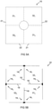
- FIG. 1 is a schematic illustration of clusters 31, 32 of radiators. The radiators are not illustrated.
- Each first cluster 31 provides an electric field 41 parallel to a first direction. This defines a first polarization.
- the first clusters 31 form a first group 21 of clusters. In the illustrated example two first clusters 31 1 , 31 2 are illustrated.
- Each second cluster 32 provides an electric field 42 parallel to a second direction. This defines a second polarization.
- the second clusters 32 form a second group 22. In the illustrated example two second clusters 32 1 , 32 2 are illustrated.
- the first direction is orthogonal to the second direction. Consequently, the first polarization and the second polarization are orthogonal.
- Each of the groups 21, 22, in these examples comprises the same number of clusters 31, 32.
- the number of clusters in each group, in this example, is an even number.
- Each cluster 31 in the first group 21 of clusters 31 1 , 31 2 provides an electric field 41 that is parallel to the first direction and each cluster 32 in the second group 22 of second clusters 32 1 , 32 2 provides an electric field 42 that is parallel to a second direction.
- the clusters are arranged in an array comprising rows and column, however other arrangements are possible.
- the array can comprise a single row/column or the clusters need not be arranged in rows/columns.
- every first cluster 31 is adjacent at least another first cluster 31 aligned along a first line.
- Every second cluster 32 is adjacent at least another second cluster aligned along a second line orthogonal to the first line.
- the first clusters 31 1 , 31 2 are diagonally offset and the second clusters 32 1 , 32 2 are diagonally offset.
- the first and second lines are diagonal.
- first clusters 31 1 , 31 2 could be vertically offset and the second clusters 32 1 , 32 2 could be vertically offset (the first and second lines are vertical (columns)). In other arrangements the first clusters 31 1 , 31 2 could be horizontally offset and the second clusters 32 1 , 32 2 could be horizontally offset (the first and second lines are horizontal (rows)).
- radiators 12 In FIG. 1 the presence of radiators 12 is indicated but the radiators, and in particular their shape, are not shown.
- Electric fields 41 are illustrated as being parallel but offset however in other examples they can be aligned.
- Electric fields 42 are illustrated as being parallel but offset however in other examples they can be aligned
- Each first cluster 31 comprises separately fed radiators 12.
- the radiators 12 of a first cluster 31 are arranged for a mutual electromagnetic coupling and for providing an electric field 41 parallel to the first direction.
- Each separately fed radiator 12 can be configured to provide an electric field 41 parallel to the first direction.
- the electric fields 41, of the radiators 12 in a cluster 31, sum to form the electric field 41 of the first cluster 31 illustrated in FIG. 2A .
- Each second cluster 32 comprises separately fed radiators 12.
- the radiators 12 of a second cluster 32 are arranged for a mutual electromagnetic coupling and for providing an electric field 42 parallel to the second direction.
- Each separately fed radiator 12 can be configured to provide an electric field 42 parallel to the second direction.
- the electric fields 42, of the radiators 12 in a cluster 32 sum to form the electric field 42 of the first cluster 31 illustrated in FIG 2A .
- the multiple separately fed radiators 12 of the first group 21 are configured to provide physically separated clusters 31 of first electric fields 41 parallel to the first direction that sum to create a combined first electric field parallel to the first direction.
- the multiple separately fed radiators 12 of the second group 22 are configured to provide physically separated clusters 32 of second electric fields 42 parallel to the second direction that sum to create a combined second electric field 42 parallel to the second direction.
- the radiators 12 can operate at the same frequency, however the first group 21 and the second group 22 operate with different polarizations.
- the separately fed radiators 12 that are configured to provide the first electric field 41 parallel to the first direction are dipole radiators and the separately fed radiators 12 that are configured to provide the second electric fields 42 parallel to the second direction are dipole radiators.
- the dipole radiators 12 can be half-wavelength dipole radiators.
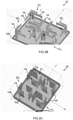
- FIGS. 2A , 2B and 2C illustrate an example of the apparatus 10.
- the apparatus 10 comprises a first group 21 of first clusters 31 of separately fed radiators 12 configured to provide electric fields 41 parallel to a first direction and a second group 22 of second clusters 32 of separately fed radiators 12 configured to provide electric fields 42 parallel to a second direction, orthogonal to the first direction.
- Each cluster 31, 32 comprises multiple separately fed radiators 12 including at least one bent dipole radiator 14.
- a bent dipole radiator 14 comprises conductive pole portions 18 extending substantially in different directions from a central feed or feeds 16, as illustrated in FIG. 4A .
- the conductive pole portions 18 are not labelled for every bent dipole radiator 14 in FIG. 2A , 2B, 2C for clarity of illustration.
- the conductive pole portions 18 can lie in a common plane.
- a conductive pole portion 18 can be straight.
- a straight conductive pole portion 18 can be a rectilinear conductive pole portion and comprise a single part in the common plane ( FIG. 4A ).
- a straight conductive pole portion 18 can comprise multiple straight parts that are either separated by gaps ( FIGS 4B, 4C ) or interconnected ( FIG. 3B ).
- the two adjacent straight parts of the conductive pole portion 18 can, in some example, be interconnected at a bend ( FIG 3B ).
- the apparatus 10 comprises a planar substrate 100 having a length and a width. At least one of the bent dipole radiators 14 of a first cluster 31 is positioned at a width-wise extremity of the planar substrate 100. At least one of the bent dipole radiators 14 of a second cluster 32 is positioned at a width-wise extremity of the planar substrate 100. This enables maximum use of the area of the planar substrate 100 in the width-wise direction.
- the bent dipole radiators 14 are center-fed half-wavelength dipole radiators.
- the conductive pole portions 18 can be quarter-wavelength conductive pole portions with the feed between the two quarter-wavelength conductive pole portions 18.
- the vector current in the conductive pole portions 18, at bandpass frequencies, defines a direction of the electric field. If one considers a bent dipole radiator 14 in a cluster 31, 32, then the other separately fed radiator 12 (for example the other bent dipole radiator 14) is physically offset in a direction orthogonal to that direction. For first clusters 31, the offset is orthogonal to the first direction (parallel to the second direction). For second clusters 32, the offset is orthogonal to the second direction (parallel to the first direction).
- each of the clusters 31, 32 comprises a pair of bent dipole radiators 14.
- Each cluster can have 180° rotation symmetry.
- the straight conductive pole portions of the bent dipole radiators 14 each comprise a single part that extend in orthogonal directions.
- the other separately fed radiator 12 that is offset from the bent dipole radiator 14 in a cluster is a straight, unbent dipole radiator comprising straight conductive pole portions 18 extending along a common line.
- the separately fed radiators 12 that are configured, in FIG 2B , to provide the first electric field parallel to the first direction are comprised in printed circuit boards 102 in FIG 3C and the separately fed radiators 12 that are configured, in FIG 3B , to provide the second electric fields parallel to the second direction are comprised in printed circuit boards 102.
- the radiators 12 can be made of aluminum sheets, molded parts or bent metal parts.
- the apparatus 10 comprises:
- FIGS 3A and 3B each illustrate an example of a cluster which can be a first cluster 31 or a second cluster 32.
- the separately fed radiators 12 of the cluster 31, 32 comprises a pair of bent dipole radiators 14 comprising conductive pole portions 18 that extend, at least partially, for example substantially, in orthogonal directions.
- the conductive pole portions lie on a square shape and in FIG. 3B the conductive pole portions 18 lie on a rectangular shape.
- one of the conductive pole portions 18 has a bend around a corner.
- the term 'straight conductive pole portion' can refer to a part that is substantially but not necessarily entirely straight in one direction or to a part that is entirely straight in one direction.
- the conductive pole portions 18 of the bent dipole radiators 14 of the cluster do not connect and there is a gap between them.
- the conductive pole portions 18 of the pair of bent dipole radiators 14 of the cluster connect and there is no gap between them.
- the conductive pole portions 18 of the bent dipole radiators 14 of a cluster 31, 32 extend in a common plane.
- the conductive pole portions 18 of different bent dipole radiators 14 are unitary and are not interrupted by a dielectric gap.
- the bent dipole radiators 14 of the cluster 31, 32 are not distinct but interconnected.
- the conductive pole portions 18 of different dipole radiators 14 are not unitary and are interrupted by a dielectric gap.
- the bent dipole radiators 14 of the cluster 31, 32 are distinct.
- the dielectric gap can be filled by dielectric material or, for example, by air.
- FIG. 4A schematically illustrates an example of a bent dipole radiator 14 comprising conductive pole portions 18 1 , 18 2 .
- the conductive pole portions 18 1 , 18 2 subtend an angle ⁇ .
- the angle ⁇ is 90°.
- the angle ⁇ can be less than or greater than 90° (see FIGS 11A, 11B ).
- FIGS. 4B and 4C illustrate an alternative example of FIG. 4A , in which one of the straight conductive pole portions 18 comprises a dielectric gap 15.
- one of the straight conductive pole portions 18 comprises a dielectric gap 15.
- at least one of the straight conductive pole portions 18 2 of the bent dipole radiator is non-unitary and is interrupted by a gap 15.
- the other straight conductive pole portion is unitary and is not interrupted by a dielectric gap 15.
- the other straight conductive pole portion 18 1 is non-unitary and is interrupted by a dielectric gap 15.
- the dielectric gap 15 can be filled by dielectric material or, for example, by air.
- the bent dipole radiators 14 are center-fed half-wavelength dipole radiators.
- the conductive pole portions 18 can be quarter-wavelength conductive pole portions with the feed between the two quarter-wavelength conductive pole portions 18.
- FIGS. 4A, 4B and 4C illustrate a feed 16 of the bent dipole antenna 14.
- the feed 16 can, for example, operate as either an input or an output for alternating currents in both the conductive pole portions 18.
- the vector sum of the electric currents in the respective conductive pole portions 18 produces a resultant virtual electric current which defines the electric field of the bent dipole radiator 14.
- first clusters 31 and the second clusters 32 were physically separate.
- a first cluster 31 1 is physically separated from a first cluster 31 2 but is not physically separated from the second clusters 32 1 , 32 2 .
- the second cluster 32 1 is physically separated from the second cluster 32 2 but is not physically separated from the first clusters 31 1 , 31 2 .
- each of the clusters 31 1 , 31 2 , 32 1 , 32 2 comprises a pair of bent dipole radiators 14 is illustrated in FIG. 5B .
- a first bent dipole radiator 14 1 of the cluster 31 1 shares a conductive pole portion 18 with a first bent dipole radiator 14 1 of the adjacent cluster 32 1
- a first bent dipole radiator 14 1 of the cluster 31 2 shares a conductive pole portion 18 with a first bent dipole radiator 14 1 of the adjacent cluster 32 2
- a second bent dipole radiator 14 2 of the cluster 31 1 shares a conductive pole portion 18 with a second bent dipole radiator 14 2 of the adjacent cluster 32 2
- a second bent dipole radiator 14 2 of the cluster 31 2 shares a conductive pole portion 18 with a second bent dipole radiator 14 2 of the adjacent cluster 32 1 .
- the first group 21 of first clusters 31 of separately fed radiators 12 including at least the bent dipole radiators 14, are configured to operate in a first passband with a first polarization and the second group 22 of second clusters 32 of separately fed radiators 12, including at least the bent dipole radiators 14 are configured to operate in the first passband with a second polarization, orthogonal to the first polarization.
- Operating in the first passband means operating with a passband that is the same bandwidth as or substantially overlaps a bandwidth of the first passband.
- a group 21/22 can be any suitable shape. It can for example be a single row/column array or an array comprising multiple row/columns. It can for example be the set of all first clusters 31/32 or it can be a sub-set of all clusters 31/32. In some examples all clusters 31/32 in the group 21/22 are operated simultaneously or operated with the same spatial filtering (beam-forming) weighting e.g. same phase offset. In some other examples only some of the clusters 31/32 in the group 21/22, for example a row or column, are operated simultaneously or with the same spatial filtering (beam-forming) weighting e.g. same phase offset.
- the unit cell illustrated in FIG 2A can be repeated to form an antenna array.
- the unit cell illustrated in FIG 2A can be repeated along a single line, with a constant repeat distance, to form an antenna array.
- the repeat distance is approximately 0.9 times an operational wavelength of the antenna array.
- the unit cell illustrated in FIG 2A has been repeated three times vertically with constant spacing to create two antenna arrays 40 1 , 40 2 .
- the unit cell illustrated in FIG 2A can be repeated multiple times horizontally and/or vertically.
- the clusters 31 1 , 32 2 of a first column of the unit cells form the first antenna array 40 1 .
- the clusters 31 1 have a first polarization and the clusters 32 2 have a second polarization that is orthogonal to the first polarization.
- the clusters 31 2 , 32 1 of a second column of the unit cells form the second antenna array 40 2 .
- the clusters 31 2 have a first polarization and the clusters 32 1 have a second polarization that is orthogonal to the first polarization.
- the first antenna array 40 1 comprises a first group of first clusters 31 1 of separately fed radiators 12 configured to provide first electric fields parallel to a first direction,
- the second antenna array 40 2 comprises a third group of first clusters 31 2 of separately fed radiators 12 configured to provide first electric fields parallel to a first direction,
- the first clusters 31 1 of the first group and the second clusters 32 2 of the second group can alternate in a first single line comprising the first clusters 31 1 of the first group and the second clusters 31 2 of the second group
- the first clusters 31 2 of the third group and the second clusters 32 1 of the fourth group alternate, in a further second single line, comprising the first clusters 31 2 of the third group and the second clusters 32 1 of the fourth group.
- all clusters 31 1 in the first antenna array 40 1 are operated with a first phase offset and all clusters 32 2 in the first antenna 40 1 are operated with a second phase offset.
- all clusters 31 2 in a second antenna 40 2 are operated with a third phase offset and all clusters 32 1 in the second antenna 40 2 are operated with a fourth phase offset.
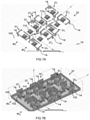
- FIGS. 7A, 7B , 9 illustrate an example in which the apparatus 10 further comprises at least some additional radiators 110 configured to operate in a second frequency passband that is distinct from the first passband. Only some of the additional radiators 110 are labelled in the FIGS. Distinct means that the passbands do not overlap.
- the separately fed radiators 12 are lower frequency radiators configured to operate in a lower-frequency passband.
- the second frequency passband is a higher frequency passband that is higher than and distinct from the lower frequency passband.
- the clusters 31, 32 of radiators 12 are arranged in an array of rows and columns.
- the additional radiators 110 are arranged in an array of rows and columns. In the FIGs only some of the additional radiators 110 are labelled. The spacing between the additional radiators 110 in at least one direction is less than a spacing between first clusters 31 in that direction.
- At least some of the higher-frequency radiators 110 are comprised within clusters 31, 32. Also, in these examples at least some of the higher-frequency radiators 110 are located outside of the clusters 31, 32.
- the higher-frequency radiators 110 are positioned in a space between the bent dipole radiators 14 of adjacent clusters 31, 32.
- FIG. 7B illustrates an example similar to that illustrated in FIG. 7A .
- the radiator elements 12, that is the bent dipole radiators 14 of the clusters 31, 32 are supported and formed within printed circuit boards 102.
- Printed circuit boards 102 are also used to support the separately fed radiators 12 in FIG 9 .
- FIG. 8 illustrates an apparatus 10 similar to that illustrated in FIG. 6B, in which the bent dipole radiators 14 are supported by and formed within printed circuit boards.
- FIG. 9 illustrates an example similar to that illustrated in FIGS. 7A and 7B except that the adjacent bent dipole radiators 14 of adjacent first and second clusters 31, 32 share a common conductive pole portion 18 as previously described in relation to FIG. 6B.
- a bent dipole radiator 14 of a cluster 31 of the first group 21 and a bent dipole radiator 14 of a cluster 31 of the second group 22 share a common conductive portion 18.
- each cluster 31, 32 comprises a bent dipole radiator 14 and a straight dipole radiator 12.
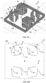
- FIGS. 10A and 10B illustrate the same apparatus 10 that has been rotated by 90°.
- the straight dipole radiator 12 comprises straight conductive pole portions 18 that extend along a common line.
- the flat dipole radiator 12 is offset from the bent dipole radiator 14 parallel to the first direction.
- the flat dipole radiator 12 is offset from the bent dipole radiator 14 parallel to the second direction.
- the straight dipole radiator 12 is a straight, unbent dipole radiator comprising straight conductive pole portions 18 extending in opposite directions along a common line.
- the angle ⁇ is 180°.
- FIGS. 11A and 11B demonstrates that the bent dipole radiator 14 need not have its straight conductive pole portions 18 extending in orthogonal directions. That is ⁇ ⁇ 90°. In this example the angle ⁇ between the straight conductive pole portions 18 of the bent dipole radiator 14 is greater than 90°.
- Each of the pair of bent dipole radiators 14 in a cluster 31, 32 has the same angle ⁇ between the straight conductive pole portions 18 of the bent dipole radiator 14.
- FIG 2A and FIG 6 illustrate and describe an apparatus 10 comprising:
- the first clusters 31 of the first group 21 are arranged diagonally in the unit cell and the second clusters 32 of the second group 22 are arranged diagonally (in an orthogonal direction) in the unit cell.
- the first clusters 31 of the first group 21 are arranged in a column formed by repeated unit cells and the second clusters 32 of the second group 22 are arranged in the same column.
- the first clusters 31 and the second clusters 32 of the same column are interleaved.
- a bandpass is a frequency range over which an antenna can efficiently operate.
- a bandpass may be defined as where the return loss S11 of the antenna is greater than an operational threshold T.
- the above described examples find application as enabling components of: automotive systems; telecommunication systems; electronic systems including consumer electronic products; distributed computing systems; media systems for generating or rendering media content including audio, visual and audio visual content and mixed, mediated, virtual and/or augmented reality; personal systems including personal health systems or personal fitness systems; navigation systems; user interfaces also known as human machine interfaces; networks including cellular, non-cellular, and optical networks; ad-hoc networks; the internet; the internet of things; virtualized networks; and related software and services.
- a property of the instance can be a property of only that instance or a property of the class or a property of a sub-class of the class that includes some but not all of the instances in the class. It is therefore implicitly disclosed that a feature described with reference to one example but not with reference to another example, can where possible be used in that other example as part of a working combination but does not necessarily have to be used in that other example.
- 'a' or 'the' is used in this document with an inclusive not an exclusive meaning. That is any reference to X comprising a/the Y indicates that X may comprise only one Y or may comprise more than one Y unless the context clearly indicates the contrary. If it is intended to use 'a' or 'the' with an exclusive meaning then it will be made clear in the context. In some circumstances the use of 'at least one' or 'one or more' may be used to emphasis an inclusive meaning but the absence of these terms should not be taken to infer any exclusive meaning.
- the presence of a feature (or combination of features) in a claim is a reference to that feature or (combination of features) itself and also to features that achieve substantially the same technical effect (equivalent features).
- the equivalent features include, for example, features that are variants and achieve substantially the same result in substantially the same way.
- the equivalent features include, for example, features that perform substantially the same function, in substantially the same way to achieve substantially the same result.
Landscapes
- Engineering & Computer Science (AREA)
- Computer Networks & Wireless Communication (AREA)
- Details Of Aerials (AREA)
Priority Applications (1)
| Application Number | Priority Date | Filing Date | Title |
|---|---|---|---|
| EP20197063.9A EP3972049A1 (fr) | 2020-09-18 | 2020-09-18 | Réseau d'antennes à double polarisation |
Applications Claiming Priority (1)
| Application Number | Priority Date | Filing Date | Title |
|---|---|---|---|
| EP20197063.9A EP3972049A1 (fr) | 2020-09-18 | 2020-09-18 | Réseau d'antennes à double polarisation |
Publications (1)
| Publication Number | Publication Date |
|---|---|
| EP3972049A1 true EP3972049A1 (fr) | 2022-03-23 |
Family
ID=72603340
Family Applications (1)
| Application Number | Title | Priority Date | Filing Date |
|---|---|---|---|
| EP20197063.9A Withdrawn EP3972049A1 (fr) | 2020-09-18 | 2020-09-18 | Réseau d'antennes à double polarisation |
Country Status (1)
| Country | Link |
|---|---|
| EP (1) | EP3972049A1 (fr) |
Citations (5)
| Publication number | Priority date | Publication date | Assignee | Title |
|---|---|---|---|---|
| EP3067987A1 (fr) * | 2013-11-05 | 2016-09-14 | KMW Inc. | Antenne de communication sans fil multibande, à polarisations multiples |
| CN105977652A (zh) * | 2016-07-07 | 2016-09-28 | 京信通信技术(广州)有限公司 | 双频阵列天线 |
| EP3089270A1 (fr) * | 2013-12-23 | 2016-11-02 | Huawei Technologies Co., Ltd. | Antenne à réseau multifréquence |
| US20170358870A1 (en) * | 2016-06-14 | 2017-12-14 | Communication Components Antenna Inc. | Dual dipole omnidirectional antenna |
| US10224643B2 (en) * | 2013-05-14 | 2019-03-05 | Kmw Inc. | Radio communication antenna having narrow beam width |
-
2020
- 2020-09-18 EP EP20197063.9A patent/EP3972049A1/fr not_active Withdrawn
Patent Citations (5)
| Publication number | Priority date | Publication date | Assignee | Title |
|---|---|---|---|---|
| US10224643B2 (en) * | 2013-05-14 | 2019-03-05 | Kmw Inc. | Radio communication antenna having narrow beam width |
| EP3067987A1 (fr) * | 2013-11-05 | 2016-09-14 | KMW Inc. | Antenne de communication sans fil multibande, à polarisations multiples |
| EP3089270A1 (fr) * | 2013-12-23 | 2016-11-02 | Huawei Technologies Co., Ltd. | Antenne à réseau multifréquence |
| US20170358870A1 (en) * | 2016-06-14 | 2017-12-14 | Communication Components Antenna Inc. | Dual dipole omnidirectional antenna |
| CN105977652A (zh) * | 2016-07-07 | 2016-09-28 | 京信通信技术(广州)有限公司 | 双频阵列天线 |
Similar Documents
| Publication | Publication Date | Title |
|---|---|---|
| EP3975337B1 (fr) | Unité d'antenne et dispositif terminal | |
| TWI533513B (zh) | 平板雙極化天線 | |
| EP3089270B1 (fr) | Antenne à réseau multifréquence | |
| TWI473347B (zh) | 平板雙極化天線 | |
| CN110649366B (zh) | 一种天线和电子设备 | |
| CN108767452B (zh) | 一种高性能双极化辐射单元及隔离度调节方法 | |
| TWI540791B (zh) | 平板雙極化天線及複合天線 | |
| CN105493348A (zh) | 多波段共口径天线 | |
| EP3214773A1 (fr) | Dispositif réseau d'étalonnage et de couplage de réseau d'antennes et procédé d'étalonnage, et support d'informations | |
| CN104037500A (zh) | 天线装置和用于设置天线装置的方法 | |
| US11289823B2 (en) | Antenna and electronic device using same | |
| CA2616434A1 (fr) | Antenne plane | |
| WO2017101722A1 (fr) | Antenne réseau plan et dispositif de communication | |
| US11450964B2 (en) | Antenna assembly with a conductive cage | |
| EP4040602B1 (fr) | Réseau d'antennes à plaque | |
| WO2021104147A1 (fr) | Procédé et dispositif de formation de faisceau | |
| CN102651504B (zh) | 平板双极化天线 | |
| US11901614B2 (en) | Low loss wideband radiator for base station antenna | |
| CN104900993A (zh) | 平板双极化天线 | |
| CN210350084U (zh) | 一种天线和电子设备 | |
| CN110649370B (zh) | 一种天线单元和电子设备 | |
| EP3972049A1 (fr) | Réseau d'antennes à double polarisation | |
| CN110649376B (zh) | 一种天线和电子设备 | |
| EP4033604A1 (fr) | Antenne dipôle | |
| CN105633564B (zh) | 平板双极化天线及复合天线 |
Legal Events
| Date | Code | Title | Description |
|---|---|---|---|
| PUAI | Public reference made under article 153(3) epc to a published international application that has entered the european phase |
Free format text: ORIGINAL CODE: 0009012 |
|
| STAA | Information on the status of an ep patent application or granted ep patent |
Free format text: STATUS: THE APPLICATION HAS BEEN PUBLISHED |
|
| AK | Designated contracting states |
Kind code of ref document: A1 Designated state(s): AL AT BE BG CH CY CZ DE DK EE ES FI FR GB GR HR HU IE IS IT LI LT LU LV MC MK MT NL NO PL PT RO RS SE SI SK SM TR |
|
| STAA | Information on the status of an ep patent application or granted ep patent |
Free format text: STATUS: THE APPLICATION IS DEEMED TO BE WITHDRAWN |
|
| 18D | Application deemed to be withdrawn |
Effective date: 20220924 |