EP3972241A1 - Informationsverarbeitungsvorrichtung, informationsverarbeitungsverfahren und programm - Google Patents
Informationsverarbeitungsvorrichtung, informationsverarbeitungsverfahren und programm Download PDFInfo
- Publication number
- EP3972241A1 EP3972241A1 EP19929702.9A EP19929702A EP3972241A1 EP 3972241 A1 EP3972241 A1 EP 3972241A1 EP 19929702 A EP19929702 A EP 19929702A EP 3972241 A1 EP3972241 A1 EP 3972241A1
- Authority
- EP
- European Patent Office
- Prior art keywords
- content
- control unit
- user
- information processing
- display
- Prior art date
- Legal status (The legal status is an assumption and is not a legal conclusion. Google has not performed a legal analysis and makes no representation as to the accuracy of the status listed.)
- Pending
Links
Images







Classifications
-
- G—PHYSICS
- G09—EDUCATION; CRYPTOGRAPHY; DISPLAY; ADVERTISING; SEALS
- G09G—ARRANGEMENTS OR CIRCUITS FOR CONTROL OF INDICATING DEVICES USING STATIC MEANS TO PRESENT VARIABLE INFORMATION
- G09G3/00—Control arrangements or circuits, of interest only in connection with visual indicators other than cathode-ray tubes
- G09G3/001—Control arrangements or circuits, of interest only in connection with visual indicators other than cathode-ray tubes using specific devices not provided for in groups G09G3/02 - G09G3/36, e.g. using an intermediate record carrier such as a film slide; Projection systems; Display of non-alphanumerical information, solely or in combination with alphanumerical information, e.g. digital display on projected diapositive as background
-
- G—PHYSICS
- G02—OPTICS
- G02B—OPTICAL ELEMENTS, SYSTEMS OR APPARATUS
- G02B27/00—Optical systems or apparatus not provided for by any of the groups G02B1/00 - G02B26/00, G02B30/00
- G02B27/01—Head-up displays
- G02B27/0179—Display position adjusting means not related to the information to be displayed
-
- G—PHYSICS
- G02—OPTICS
- G02B—OPTICAL ELEMENTS, SYSTEMS OR APPARATUS
- G02B27/00—Optical systems or apparatus not provided for by any of the groups G02B1/00 - G02B26/00, G02B30/00
- G02B27/0093—Optical systems or apparatus not provided for by any of the groups G02B1/00 - G02B26/00, G02B30/00 with means for monitoring data relating to the user, e.g. head-tracking, eye-tracking
-
- G—PHYSICS
- G02—OPTICS
- G02B—OPTICAL ELEMENTS, SYSTEMS OR APPARATUS
- G02B27/00—Optical systems or apparatus not provided for by any of the groups G02B1/00 - G02B26/00, G02B30/00
- G02B27/01—Head-up displays
- G02B27/017—Head mounted
-
- G—PHYSICS
- G06—COMPUTING OR CALCULATING; COUNTING
- G06F—ELECTRIC DIGITAL DATA PROCESSING
- G06F3/00—Input arrangements for transferring data to be processed into a form capable of being handled by the computer; Output arrangements for transferring data from processing unit to output unit, e.g. interface arrangements
- G06F3/01—Input arrangements or combined input and output arrangements for interaction between user and computer
- G06F3/017—Gesture based interaction, e.g. based on a set of recognized hand gestures
-
- G—PHYSICS
- G06—COMPUTING OR CALCULATING; COUNTING
- G06T—IMAGE DATA PROCESSING OR GENERATION, IN GENERAL
- G06T19/00—Manipulating three-dimensional [3D] models or images for computer graphics
- G06T19/006—Mixed reality
-
- G—PHYSICS
- G09—EDUCATION; CRYPTOGRAPHY; DISPLAY; ADVERTISING; SEALS
- G09G—ARRANGEMENTS OR CIRCUITS FOR CONTROL OF INDICATING DEVICES USING STATIC MEANS TO PRESENT VARIABLE INFORMATION
- G09G5/00—Control arrangements or circuits for visual indicators common to cathode-ray tube indicators and other visual indicators
- G09G5/36—Control arrangements or circuits for visual indicators common to cathode-ray tube indicators and other visual indicators characterised by the display of a graphic pattern, e.g. using an all-points-addressable [APA] memory
- G09G5/38—Control arrangements or circuits for visual indicators common to cathode-ray tube indicators and other visual indicators characterised by the display of a graphic pattern, e.g. using an all-points-addressable [APA] memory with means for controlling the display position
-
- G—PHYSICS
- G02—OPTICS
- G02B—OPTICAL ELEMENTS, SYSTEMS OR APPARATUS
- G02B27/00—Optical systems or apparatus not provided for by any of the groups G02B1/00 - G02B26/00, G02B30/00
- G02B27/01—Head-up displays
- G02B27/0101—Head-up displays characterised by optical features
- G02B2027/0123—Head-up displays characterised by optical features comprising devices increasing the field of view
-
- G—PHYSICS
- G02—OPTICS
- G02B—OPTICAL ELEMENTS, SYSTEMS OR APPARATUS
- G02B27/00—Optical systems or apparatus not provided for by any of the groups G02B1/00 - G02B26/00, G02B30/00
- G02B27/01—Head-up displays
- G02B27/0101—Head-up displays characterised by optical features
- G02B2027/0138—Head-up displays characterised by optical features comprising image capture systems, e.g. camera
-
- G—PHYSICS
- G02—OPTICS
- G02B—OPTICAL ELEMENTS, SYSTEMS OR APPARATUS
- G02B27/00—Optical systems or apparatus not provided for by any of the groups G02B1/00 - G02B26/00, G02B30/00
- G02B27/01—Head-up displays
- G02B27/0101—Head-up displays characterised by optical features
- G02B2027/014—Head-up displays characterised by optical features comprising information/image processing systems
-
- G—PHYSICS
- G09—EDUCATION; CRYPTOGRAPHY; DISPLAY; ADVERTISING; SEALS
- G09G—ARRANGEMENTS OR CIRCUITS FOR CONTROL OF INDICATING DEVICES USING STATIC MEANS TO PRESENT VARIABLE INFORMATION
- G09G2340/00—Aspects of display data processing
- G09G2340/04—Changes in size, position or resolution of an image
- G09G2340/0464—Positioning
-
- G—PHYSICS
- G09—EDUCATION; CRYPTOGRAPHY; DISPLAY; ADVERTISING; SEALS
- G09G—ARRANGEMENTS OR CIRCUITS FOR CONTROL OF INDICATING DEVICES USING STATIC MEANS TO PRESENT VARIABLE INFORMATION
- G09G2340/00—Aspects of display data processing
- G09G2340/12—Overlay of images, i.e. displayed pixel being the result of switching between the corresponding input pixels
- G09G2340/125—Overlay of images, i.e. displayed pixel being the result of switching between the corresponding input pixels wherein one of the images is motion video
-
- G—PHYSICS
- G09—EDUCATION; CRYPTOGRAPHY; DISPLAY; ADVERTISING; SEALS
- G09G—ARRANGEMENTS OR CIRCUITS FOR CONTROL OF INDICATING DEVICES USING STATIC MEANS TO PRESENT VARIABLE INFORMATION
- G09G2354/00—Aspects of interface with display user
Definitions
- the present disclosure relates to an information processing apparatus, an information processing method, and a program.
- Patent Literature 1 discloses a head mounted display for realizing AR technology.
- Patent Literature 1 JP 2011-2753 A
- an information processing apparatus includes: a control unit that controls display of AR content by a display device arranged in front of eyes of a user, wherein the control unit controls a manner of displaying the AR content so that a degree of decrease in a user's viewing level of a real space is reduced as compared with a case where original content is displayed.
- an information processing method includes controlling, by a processor, display of AR content by a display device arranged in front of eyes of a user, wherein the controlling further includes controlling a manner of displaying the AR content so that a degree of decrease in user's viewing level of a real space is reduced as compared with a case where original content is displayed.
- a program causes a computer to function as an information processing apparatus including a control unit that controls display of AR content by a display device arranged in front of eyes of a user, wherein the control unit controls a manner of displaying the AR content so that a degree of decrease in user's viewing level of a real space is reduced as compared with a case where original content is displayed.
- a user can view AR content displayed on a display while visually recognizing the real space by using a see-through (including video see-through and optical see-through) head mounted display such as the one disclosed in Patent Literature 1.
- a see-through including video see-through and optical see-through
- FIG. 1 is a diagram for explaining display of AR content by a general head mounted display.
- FIG. 1 illustrates an example of a field of view of a user wearing a general head mounted display 90. Note that, in the example illustrated in FIG. 1 , a user views video content provided by a video streaming service as AR content C by using the head mounted display 90.
- the head mounted display 90 displays the AR content C in a central portion of the field of view of the user, most of the field of view of the user is occupied by the AR content C, and therefore a user's viewing level of the real space (that is, an object, scenery, or the like that can be visually recognized through a see-through display) significantly decreases.
- the user In a case where the user is performing an action such as walking or driving a vehicle, the user is hindered by the displayed AR content C and cannot visually recognize an object, terrain, or the like existing in a moving direction and may, for example, collide with something or falls over.
- an information processing apparatus includes a control unit that controls display of AR content by a display device arranged in front of eyes of a user. Furthermore, one of features of the control unit according to an embodiment of the present disclosure is to control a manner of displaying the AR content so that a degree of decrease in the user's viewing level of the real space is reduced as compared with a case where original content is displayed.
- FIG. 2 is a diagram illustrating an example of displayed AR content according to the present embodiment.
- FIG. 2 illustrates an example of a field of view of a user wearing a head mounted display 20 according to the present embodiment.
- the head mounted display is an example of an information processing apparatus according to the present disclosure.
- the user is viewing video content provided by a video streaming service as AR content as in FIG. 1 .
- the head mounted display 20 displays the AR content C in which background excluding main subjects MS1 to MS3 corresponding to three persons has been removed from the video content (referred to as original content).
- a main subject according to the present embodiment may be, for example, a subject that the user is assumed to pay more attention to in original content such as video content.
- original content such as video content.
- the main subject according to the present embodiment may be a person (performer) as illustrated in FIG. 2 .
- the information processing method it is possible to extract, from original content, a region corresponding to a subject that a user is assumed to pay more attention to, that is, a subject that the user is assumed to be more interested in viewing, and to display the region as AR content.
- the display control illustrated in FIG. 2 is merely an example, and the display control of AR content according to the present embodiment is not limited to such an example. Specific examples of the display control according to the present embodiment and a configuration for realizing the various types of display control will be described in detail below.
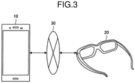
- FIG. 3 is a diagram illustrating a configuration example of the information processing system according to the present embodiment.
- the information processing system according to the present embodiment includes an information processing terminal 10 and the head mounted display 20. Furthermore, the information processing terminal 10 and the head mounted display 20 are connected so as to be communicable with each other over a network 30.
- the information processing terminal 10 is an example of an information processing apparatus that realizes the information processing method according to the present embodiment.
- the information processing terminal 10 according to the present embodiment controls the AR display by the head mounted display 20 via the network 30.
- the information processing terminal 10 according to the present embodiment may be, for example, a small electronic device that is easy to carry around, such as a smartphone.
- the information processing terminal 10 according to the present embodiment may be a server.
- the head mounted display 20 according to the present embodiment is a device that includes a see-through display and enables a user to visually recognize a real space and view AR content.
- the head mounted display 20 according to the present embodiment may display AR content, for example, on the basis of control by the information processing terminal 10.
- the head mounted display 20 may be, for example, an eyeglass-type or preventative device.
- the head mounted display 20 may be, for example, an external device that can be mounted on normal glasses or the like.
- the network 30 has a function of connecting the information processing terminal 10 and the head mounted display 20.
- the network 30 may include a wireless communication network such as Wi-Fi (registered trademark) or Bluetooth (registered trademark).
- the network 30 may include a mobile communication network such as long term evolution (LTE).
- the configuration example of the information processing system according to the present embodiment has been described above. Note that the configuration described above with reference to FIG. 3 is merely an example, and the configuration of the information processing system according to the present embodiment is not limited to such an example.
- the case where the information processing terminal 10 controls display of AR content by the head mounted display 20 over the network 30 has been described above as an example.
- control by the information processing terminal 10 is not necessarily required, and the head mounted display 20 according to the present embodiment may independently realize the information processing method according to the present embodiment.
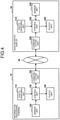
- FIG. 4 is a block diagram illustrating functional configuration examples of the information processing terminal 10 and the head mounted display 20 according to the present embodiment. Note that, in the following, a case where the information processing terminal 10 controls AR display by the head mounted display 20 will be described as a main example.
- a photographing unit 110 has a function of photographing a real space.
- a control unit 130 which will be described later, may control AR display by the head mounted display 20 on the basis of image information of the real space photographed by the photographing unit 110.
- the photographing unit 110 is arranged so as to be capable of photographing the same direction as the direction in which the user visually recognizes the real space through the head mounted display 20.
- a sensor unit 120 has a function of collecting various kinds of sensor information such as acceleration and angular velocity.
- the control unit 130 may control AR display by the head mounted display 20 on the basis of the sensor information collected by the sensor unit 120.
- the control unit 130 according to the present embodiment collectively controls constituent elements included in the information processing terminal 10. Furthermore, the control unit 130 according to the present embodiment has a function of controlling AR display by the head mounted display 20 on the basis of photographed image information and collected sensor information.
- One of features of the control unit 130 according to the present embodiment is to control a manner in which AR content is displayed by an output unit 240 so that a degree of decrease in user's viewing level of the real space is reduced as compared with a case where original content is displayed by the output unit 240 of the head mounted display 20.
- control unit 130 may cause the output unit 240 to display AR content obtained by removing background excluding a main subject from original content.
- the above manner of displaying may include display content, a display position, a display timing, and the like of the AR content. Details of the functions of the control unit 130 according to the present embodiment will be described later.
- the output unit 140 according to the present embodiment outputs various kinds of information on the basis of control of the control unit 130.
- the output unit 140 according to the present embodiment includes a display device, a speaker, or the like.
- a communication unit 150 performs information communication with the head mounted display 20 over the network 30.
- a photographing unit 210 according to the present embodiment has a function of photographing a real space.
- the photographing unit 210 according to the present embodiment is arranged so as to be capable of photographing the same direction as the direction in which the user visually recognizes the real space through an output unit 240, which will be described later.
- a sensor unit 220 has a function of collecting various kinds of sensor information such as acceleration and angular velocity.
- a control unit 230 collectively controls constituent elements included in the head mounted display 20. Furthermore, the control unit 230 performs processing related to display of AR content on the basis of control of the information processing terminal 10. For example, the control unit 230 may deliver image information, a control signal, and the like related to AR content generated by the control unit 130 of the information processing terminal 10 to the output unit 240.
- control unit 230 may have a display control function equivalent to that of the control unit 130 of the information processing terminal 10. That is, in this case, the control unit 230 may control a manner of displaying AR content so that a degree of decrease in user's viewing level of the real space is reduced as compared with a case where original content is displayed.
- the output unit 240 displays AR content on the basis of control of the control unit 130 or the control unit 230.
- the output unit 240 according to the present embodiment includes at least a display device arranged in front of the eyes of the user wearing the head mounted display 20.
- the output unit 240 may include a speaker or the like for outputting sound accompanying the AR content.
- a communication unit 150 performs information communication with the information processing terminal 10 over the network 30.
- the functional configuration examples of the information processing terminal 10 and the head mounted display 20 according to the present embodiment have been described above. Note that the configurations described above with reference to FIG. 4 are merely an example, and the functional configurations of the information processing terminal 10 and the head mounted display 20 according to the present embodiment are not limited to such an example. As described above, the head mounted display 20 according to the present embodiment can display AR content independently without being controlled by the information processing terminal 10.
- the head mounted display 20 according to the present embodiment can display AR content independently or on the basis of control of the information processing terminal 10.
- FIG. 5 is a block diagram illustrating an example of a detailed configuration in a case where the head mounted display 20 according to the present embodiment independently performs display control of AR content.
- control unit 230 includes a system on chip (SoC), an OS, an AR framework, an application, and the like.
- SoC system on chip
- the control unit 230 generates an environment map and a pose graph (posture graph) by performing simultaneous localization and mapping (SLAM) on the basis of image information photographed by a camera included in the photographing unit 210 and sensor information (acceleration information and angular velocity information) received from an inertial measurement unit (IMU) included in the sensor unit 220.
- SoC system on chip
- OS an AR framework
- application an application
- the control unit 230 generates an environment map and a pose graph (posture graph) by performing simultaneous localization and mapping (SLAM) on the basis of image information photographed by a camera included in the photographing unit 210 and sensor information (acceleration information and angular velocity information) received from an inertial measurement unit (IMU) included in the sensor unit 220.
- IMU inertial measurement unit
- control unit 230 can recognize a space (environment map) including an object on the basis of the image information and the sensor information, and can grasp position and posture (pose graph) of the camera in the recognized space.
- FIG. 6 is a diagram illustrating a configuration example of software for realizing SLAM according to the present embodiment. As illustrated in FIG. 6 , the software that realizes SLAM according to the present embodiment may be divided into a front end and a back end.
- the image information acquired by the photographing unit 210 and the sensor information acquired by the sensor unit 220 are sequentially input, and association of data, real-time update of the environment map, and generation of a pose graph are performed.
- SLAM is an estimation technique based on sensor information
- errors accumulate as the environment map becomes larger. Therefore, when the same point is observed by looping the same path, it is important to significantly reduce the accumulated errors by detecting the loop and closing the loop. Therefore, in the front end, loop detection for detecting such a loop may be executed.
- the back end batch processing of greatly updating the environment map, such as synchronizing the environment map with the server, is executed. Furthermore, in the back end, pose correction accompanying loop detection and the like are executed. Since the update and use of the environment map increase an amount of calculation, it is possible to reduce the amount of calculation and secure performance by using the pose graph for estimating the position on the basis of movement of the head mounted display 20. Note that the back end may be executed in a thread different from the front end. This makes it possible to perform processing without affecting a real-time property.
- the control unit 230 can determine a manner of displaying AR content such as display content, a display position, a size, and a display timing of the AR content on the basis of the environment map and the pose graph generated as described above, and can cause the display device included in the output unit 240 to output the determined manner.
- AR content can be displayed by the head mounted display 20 alone.
- the control unit 230 since the control unit 230 performs all the processing related to the SLAM and the display control of AR content, the control unit 230 needs to have abundant calculation resources, which invites an increase in size of the head mounted display 20.
- the processing related to the SLAM and the display control of AR content is performed by the information processing terminal 10, so that a processing load on the head mounted display 20 side can be reduced, and the head mounted display 20 can be further reduced in size.
- FIG. 7 is a block diagram illustrating an example of a detailed configuration in a case where the information processing terminal 10 performs the SLAM and the display control of AR content according to the present embodiment.
- control unit 130 has a configuration similar to the control unit 230 illustrated in FIG. 5 .
- the control unit 130 can receive image information and sensor information from the photographing unit 210 and the sensor unit 220 of the head mounted display 20, respectively over the communication unit 150 and a wireless communication device included in the communication unit 250 and execute processing related to the SLAM and the AR content display.
- control unit 230 may recognize a gesture of the user from the received image information by using a gesture recognition device and control the display of AR content on the basis of a result of the recognition.
- the gesture recognition function of the control unit 230 according to the present embodiment will be described later.
- control unit 230 of the head mounted display 20 may detect a difference between pieces of image information input in time series from the photographing unit 210 by using a motion detector, and transmit the image information to the information processing terminal 10 only in a case where the difference is detected, that is, only in a case where there is a change in the image information. According to such control, an amount of transmitted image information can be reduced, and traffic can be effectively suppressed.
- the display control of AR content according to the present embodiment will be described in detail with a specific example.
- the head mounted display 20 according to the present embodiment displays AR content obtained by removing background excluding a main subject from original content
- the head mounted display 20 according to the present embodiment is not limited to the above example, and can display AR content in various manners.
- the control unit 130 of the information processing terminal 10 controls display of AR content by the output unit 240 of the head mounted display 20 will be described below as a main example.
- control unit 130 may control a manner of displaying the AR content according to a reproduced scene of the original content.
- the control unit 130 according to the present embodiment may cause the output unit 240 to display the AR content corresponding to the reproduced scene only in a case where the reproduced scene of the original content includes a main subject.
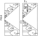
- FIG. 8 is a diagram for explaining display control of AR content according to a reproduced scene including a main subject according to the present embodiment.
- a reproduced scene that does not include a main subject such as an artist is often used in a video content such as a music promotion video.
- a situation is assumed in which the user is distracted from a real space by the reproduced scene that changes frequently.
- the control unit 130 may cause the output unit 240 to display the AR content C corresponding to the reproduced scene only in a case where the reproduced scene includes a main subject MS.
- a display time of the AR content C can be shortened and a degree of decrease in user's viewing level of the real space can be effectively kept small by limiting displayed content of the AR content C to a subject which the user wants to gaze at.
- control unit 130 may set a person appearing in video content as a main subject and extract a reproduced scene including the main subject by performing face detection processing or the like. Furthermore, the control unit 130 can also extract a reproduced scene including a main subject on the basis of metadata accompanying the video content. For example, in a case where subject information for each reproduced scene (frame) is included in the metadata, the user may be permitted to designate a main subject (for example, only a vocal among persons) that the user wants to view.
- a main subject for example, only a vocal among persons
- control unit 130 may extract a representative image for each reproduced scene from the original video content and cause the output unit 240 to output the representative image as AR content.
- FIG. 9 is a diagram for explaining display control of AR content corresponding to the representative image for each reproduced scene according to the present embodiment.
- control unit 130 may extract a representative image (still image) for each reproduced scene and cause the output unit 240 to continuously output the representative image as AR content while the same reproduced scene continues.
- control unit 130 continues to cause the output unit 240 to display a representative image of "intro" as AR content C1.
- control unit 130 causes the output unit 240 to display a representative image of "Verse” as AR content C and continues the display until the end of "Verse".
- visual information representing a reproduced scene is presented to the user while reducing a degree of decrease in user's viewing level of the real space by making a change in the AR content less frequent, and thereby a user's degree of satisfaction can be secured.
- the control unit 130 may display the AR content C at a periphery of the field of view of the user. According to such display control, a central portion of the field of view of the user is not blocked, and therefore a degree of decrease in user's viewing level of the real space can be reduced.
- control unit 130 may dynamically control a display position of the AR content on the basis of a reproduced scene of video content or a user's action status.
- FIG. 10 is a diagram for explaining display position control of AR content based on a reproduced scene or a user's action status according to the present embodiment.
- FIG. 10 illustrates a display example of AR content in a case where the user is performing an action such as walking.
- the control unit 130 may display the AR content C in a peripheral portion of the field of view of the user, as described above. According to such display control, it is possible to make the central portion of the field of view of the user unoccupied, thereby reducing a degree of decrease in user's viewing level of the real space.
- control unit 130 may perform control so that the main subjects MS1 to MS3 are displayed separately in a peripheral portion of the field of view of the user.
- FIG. 10 illustrates a display example of the AR content in a case where the user is stationary or in a case where a reproduced scene is a main scene in the original content.
- control unit 130 may display the AR content in the peripheral portion of the user's field of view in a case where the user is moving and may display the AR content in the central portion of the user's field of view in a case where the user is stationary.
- a reproduced scene is a main scene in the original content, such as a chorus part in a music promotion video
- a reproduced scene is a main scene in the original content, such as a chorus part in a music promotion video
- control unit 130 may display the AR content in a peripheral portion of the user's field of view in a case where the reproduced scene is not a main scene in the original content and may display the AR content in a central portion of the user's field of view in a case where the reproduced scene is the main scene in the original content.
- control unit 130 can dynamically control a display position of AR content on the basis of a reproduced scene of original content or a user's action status. According to such control, it is possible to realize a higher quality of AR experience by changing a degree of priority for securing a user's field of view or viewing the AR content according to a situation.
- control unit 130 can specify characteristics of each reproduced scene included in original content by analyzing the original content. For example, in a case where the original content is a music promotion video, the control unit 130 may specify characteristics of each reproduced scene on the basis of music data included in the original content.
- FIG. 11 is a flowchart illustrating a flow of specifying reproduced scene characteristics based on music data and display control of AR content based on the reproduced scene characteristics according to the present embodiment.
- control unit 130 loads original content (S1101).
- control unit 130 determines whether or not the content is reproduced for the first time (S1102).
- control unit 130 determines whether or not there is music data (S1103).
- control unit 130 ends the processing of the example.
- the control unit 130 decodes the music data (S1104).
- control unit 130 causes a speaker included in the output unit 240 to output pulse code modulation (PCM) data acquired by the decoding in step S1104 (1105).
- PCM pulse code modulation
- control unit 130 performs Fourier transform on the PCM data and executes clustering based on a power spectrogram thus acquired (S1106).
- clustering for example, it is possible to classify parts that are similar in whether or not there is output of instruments or vocal, or tone, tempo, or the like as a cluster, that is, a reproduced scene.
- FIG. 12 is a diagram illustrating an example of clustering based on music data according to the present embodiment.
- the upper part of FIG. 12 illustrates a part configuration of a piece of music "ABC".
- the music ABC includes intro, verse, bridge, chorus, interlude, and outro.
- reproduced scenes of the music data "ABC" can be classified as illustrated in the lower part of FIG. 12 .
- numbers in FIG. 12 each indicate an elapsed time from the beginning of the content.
- Such clustering data may be used for second or subsequent reproduction of the content.
- step S1102 determines whether or not there is music data (S1107).
- control unit 130 ends the series of processing.
- the control unit 130 decodes the music data (S1108).
- control unit 130 causes the speaker included in the output unit 240 to output PCM data acquired by the decoding in step S1108 (1109).
- control unit 130 controls display of the AR content on the basis of the clustering data acquired in step S1106 at the time of the first reproduction of the content (S1110).
- the control unit 130 may determine that the reproduced scene is a main scene in the original content and display the AR content C in the central part of the user's field of view as illustrated in the lower part of FIG. 10 .
- the clustering according to the present embodiment it is possible to change movement of AR content according to a speed of music or change expression of the AR content according to a property of sound.
- superimposed display for mainly displaying a person may be performed, and in the case of "sound: instruments”, an effect on background is focused, so that it can be used as an input for improving expressive power of the music scene.
- control unit 130 can specify characteristics of a reproduced scene included in original content by analyzing music data or the like and perform display control of AR content on the basis of the characteristics.
- the above method is merely an example, and an analysis method related to a reproduced scene may be appropriately selected according to the type of original content.
- the control unit 130 can also acquire characteristics of a reproduced scene from metadata or the like accompanying original content.
- clustering of music data may be performed by a server separately provided.
- clustering of music data is performed in advance in the server, and clustering data is stored.
- each user can view the AR content according to characteristics of a reproduced scene by receiving the clustering data through communication with the server.
- clustering data may be prepared only for representative pieces of content instead of generating clustering data in advance for all pieces of content including music data. For example, pieces of content that have been reproduced by users a predetermined number of times or more may be set as representative content or pieces of content that are located at the top in total number of reproductions during a predetermined period may be set as representative content.
- control unit 130 may display AR content at a position corresponding to the advertisement medium.
- FIG. 13 is a diagram for explaining display control of AR content based on a result of recognition of an object existing in the real space according to the present embodiment.
- FIG. 13 illustrates buildings B1 to B3 existing in the real space.
- Advertisement media A1 and A2 are installed in the buildings B1 and B2, respectively.
- the advertisement medium A1 may be, for example, a signboard advertisement, and the advertisement medium A2 may be, for example, a large-sized display.
- the control unit 130 can recognize the advertisement media A1 and A2 on the basis of image information photographed by the photographing unit 210 of the head mounted display 20.
- the control unit 130 may recognize the advertisement media A1 and A2 by using a detector that detects a rectangular region.
- control unit 130 can display AR content C1 and AR content C2 at positions corresponding to the recognized advertisement media A1 and A2, respectively.
- an advertisement medium existing in the real space can be used as a display medium of AR content, and it is possible to realize natural AR display that fits the scenery without narrowing a user's field of view.
- control unit 130 may use not only an advertisement medium but also various rectangular regions to display AR content.
- control unit 130 can detect a plurality of windows of the building B3 as rectangular regions and display AR content in the rectangular regions.
- control unit 130 may control the display of AR content on the basis of detection of a plane such as a wall in front of the user.
- a plane such as a wall in front of the user.
- the control unit 130 detects a wall W in front of the user on the basis of image information photographed by the photographing unit 210 of the head mounted display 20.
- control unit 130 may display AR content C1 related to notification of a message received before the detection of the wall W to have superimposed display on the wall W.
- a notification related to the message as immediate AR content may attract user's attention more than necessary, thereby lowering a user's viewing level of the real space.
- control unit 130 performs AR display related to notification of a message in a case where a plane such as a wall or a screen is detected and the user has stopped walking, allowing the user to check the message in a safer situation.
- control unit 130 can control a manner of displaying AR content on the basis of a result of recognition of various objects existing in the real space.
- control unit 130 can also control a manner of displaying AR content on the basis of, for example, a color of a recognized object or plane.
- AR content is easy to visually recognize when background is black but is hard to visually recognize when the background color is light.
- the control unit 130 may correct an entire image so that AR content becomes easy to visually recognize with respect to luminance of the recognized object or plane or may display the AR content at a more easily visible position.
- the control unit 130 may recognize a user's gesture on the basis of image information photographed by the photographing unit 210 of the head mounted display 20 and control a manner of displaying AR content on the basis of the gesture.
- the control unit 130 may determine that the input is similar to a tapping action on the information processing terminal 10 and control a manner of displaying the AR content C1 according to the input.
- control unit 130 may determine that the input is similar to a dragging action on the information processing terminal 10 and control a manner of displaying the AR content C1 according to the input.
- the user can easily and intuitively operate an application without taking out the information processing terminal 10 each time, and a more convenient AR experience can be provided.
- control unit 130 can also cause the output unit 140 to display AR content for accepting a gesture corresponding to a user's key input.
- the control unit 130 recognizes that the user has gazed at the hand UH and displays AR content C for accepting input of numeric keys on the hand UH.
- the control unit 130 can specify a number that the user desires to input by associating the display position of the AR content C with a user's gesture position.
- VR content Unlike AR content, in the case of VR content, an image is displayed on a user's entire field of view, and it is therefore very difficult to enjoy VR content while moving outdoors. Therefore, in the present embodiment, by reconstructing VR content as AR content, the user is allowed to easily enjoy favorite content outdoors.
- FIG. 16 is a diagram for explaining generation of AR content based on VR content according to the present embodiment.
- the left side of FIG. 16 illustrates a state in which a user U views 360-degree VR content VC by using a VR device 40.
- control unit 130 extracts a moving object from the VR content VC and removes a background excluding the object.
- the control unit 130 superimposes the extracted object as AR content C on a field of view FV so that the object is arranged in a direction corresponding to a direction on the VR content VC of the user.
- original content according to the present embodiment may be VR content.
- control unit 130 according to the present embodiment can also generate VR content on the basis of AR content.
- FIG. 17 is a diagram for explaining generation of VR content based on AR content according to the present embodiment.
- FIG. 17 illustrates a state in which the user U views AR content C superimposed on the field of view FV by using the head mounted display 20.
- the control unit 130 stores image information photographed by the photographing unit 210 of the head mounted display 20 and image information of the AR content C displayed on the output unit 240 in a VR format together with display position information (posture information of the head mounted display 20).
- FIG. 17 illustrates a state in which the user U views VR content VC saved as described above by using the VR device 40.
- the VR device 40 may complement image information in a direction that is not photographed by the photographing unit 210 of the head mounted display 20 by using, for example, an image generator using a machine learning method.
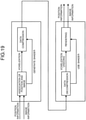
- FIGS. 18 and 19 are diagrams for explaining VR format storage of image information according to the present embodiment.
- the control unit 130 first analyzes content.
- the control unit 130 first performs separation processing on an image input from the photographing unit 210 of the head mounted display 20. Specifically, the control unit 130 separates elements included in the image into a stationary object such as a background and a moving object including a person. Furthermore, the control unit 130 further detects a plane such as the ground from the extracted stationary object.
- control unit 130 measures a distance between the detected moving object and the plane and estimates position and size of the plane.
- control unit 130 associates the positions and sizes between the plane and the moving object from the measured distance between the moving object and the plane and the estimated position and size of the plane.
- control unit 130 performs processing of arranging the moving object acquired as described above on a background image for VR content.
- control unit 130 detects a plane from the background image and estimates position and size of the plane.
- control unit 130 arranges the moving object on the background image on the basis of the estimated position and size of the plane and the relationship in position and size between the plane and the moving object acquired in the content analysis described above. According to such processing, position and size of a moving object such as a person can be naturally positioned with respect to position and size of a background.
- the control unit 130 performs voxelization and data compression of the arranged moving object.
- the control unit 130 executes the voxelization by associating the position information of the moving object with the image information.
- a voxel refers to regular grid data in a three-dimensional space. That is, the control unit 130 converts image information of the moving object into 3D point cloud data. Furthermore, the control unit 130 generates a shader for smoothing the 3D point cloud data.
- control unit 130 compresses and stores the 3D point cloud data, the shader, the position information, and the color information acquired as described above.
- control unit 130 according to the present embodiment can generate VR content based on AR content and image information obtained by photographing a real space.
- the VR device 40 first performs expansion processing of the compressed data.
- the VR device 40 can acquire the position information and the image information related to the moving object and can express the moving object in a volumetric space by undoing the voxelization and performing rendering processing by using the shader.
- FIG. 20 is a diagram illustrating an example of a system configuration that realizes sharing of an AR experience by an AR cloud according to the present embodiment.
- a system configuration for realizing sharing of an AR experience by an AR cloud is illustrated in three layers of a device, a platform, and an application.
- the device layer is a layer for input/output related to display of AR content, and includes, for example, a modem, a GNSS signal receiver, an IMU, a geomagnetic sensor, a camera (RGB, ToF), a display, a GPU, and the like.
- the platform layer is a layer that relays between the device layer and the application layer, and includes various services.
- the application layer is a layer for SLAM and display control of AR content, and associates data stored in the AR cloud and data stored locally. Specifically, in the application layer, point cloud data of a three-dimensional space stored in the AR cloud is associated with locally acquired SLAM data, and thereby position and posture of the local terminal in the three-dimensional space are specified.
- the AR content uploaded by the other terminal can be displayed at an accurate position.
- the information processing method it is possible to share an AR experience among a plurality of users by sharing information regarding an object in a real space over the cloud.
- the information processing apparatus includes a control unit that controls display of AR content by a display device arranged in front of user's eyes. Furthermore, one of features of the control unit according to an embodiment of the present disclosure is to control a manner of displaying the AR content so that a degree of decrease in the user's viewing level of the real space is reduced as compared with a case where original content is displayed. According to such a configuration, it is possible to view AR content fused with the real space more safely.
- steps related to the processing of the information processing terminal 10 in the present specification are not necessarily performed in time series in the order described in the flowchart.
- the steps related to the processing of the information processing terminal 10 may be performed in an order different from the order described in the flowchart or may be performed in parallel.
Landscapes
- Physics & Mathematics (AREA)
- Engineering & Computer Science (AREA)
- General Physics & Mathematics (AREA)
- Optics & Photonics (AREA)
- Theoretical Computer Science (AREA)
- General Engineering & Computer Science (AREA)
- Computer Hardware Design (AREA)
- Human Computer Interaction (AREA)
- Computer Graphics (AREA)
- Software Systems (AREA)
- User Interface Of Digital Computer (AREA)
- Controls And Circuits For Display Device (AREA)
Applications Claiming Priority (1)
| Application Number | Priority Date | Filing Date | Title |
|---|---|---|---|
| PCT/JP2019/019776 WO2020234939A1 (ja) | 2019-05-17 | 2019-05-17 | 情報処理装置、情報処理方法、およびプログラム |
Publications (2)
| Publication Number | Publication Date |
|---|---|
| EP3972241A1 true EP3972241A1 (de) | 2022-03-23 |
| EP3972241A4 EP3972241A4 (de) | 2022-07-27 |
Family
ID=73459237
Family Applications (1)
| Application Number | Title | Priority Date | Filing Date |
|---|---|---|---|
| EP19929702.9A Pending EP3972241A4 (de) | 2019-05-17 | 2019-05-17 | Informationsverarbeitungsvorrichtung, informationsverarbeitungsverfahren und programm |
Country Status (4)
| Country | Link |
|---|---|
| US (1) | US11846783B2 (de) |
| EP (1) | EP3972241A4 (de) |
| CN (1) | CN113875227A (de) |
| WO (1) | WO2020234939A1 (de) |
Families Citing this family (3)
| Publication number | Priority date | Publication date | Assignee | Title |
|---|---|---|---|---|
| US20220146822A1 (en) * | 2019-08-15 | 2022-05-12 | Ostendo Technologies, Inc. | Wearable Display Systems and Design Methods Thereof |
| WO2022190970A1 (ja) | 2021-03-08 | 2022-09-15 | ソニーグループ株式会社 | 情報処理装置、情報処理方法、プログラム、及び、情報処理システム |
| WO2022264377A1 (ja) * | 2021-06-17 | 2022-12-22 | 日本電気株式会社 | 情報処理装置、情報処理システム、情報処理方法及び非一時的なコンピュータ可読媒体 |
Family Cites Families (21)
| Publication number | Priority date | Publication date | Assignee | Title |
|---|---|---|---|---|
| US20020044152A1 (en) * | 2000-10-16 | 2002-04-18 | Abbott Kenneth H. | Dynamic integration of computer generated and real world images |
| JP5402293B2 (ja) | 2009-06-22 | 2014-01-29 | ソニー株式会社 | 頭部装着型ディスプレイ、及び、頭部装着型ディスプレイにおける画像表示方法 |
| US20110213664A1 (en) * | 2010-02-28 | 2011-09-01 | Osterhout Group, Inc. | Local advertising content on an interactive head-mounted eyepiece |
| US9317133B2 (en) * | 2010-10-08 | 2016-04-19 | Nokia Technologies Oy | Method and apparatus for generating augmented reality content |
| US9081177B2 (en) * | 2011-10-07 | 2015-07-14 | Google Inc. | Wearable computer with nearby object response |
| JP2015037242A (ja) * | 2013-08-13 | 2015-02-23 | ソニー株式会社 | 受信装置、受信方法、送信装置、及び、送信方法 |
| US10146057B2 (en) | 2014-02-20 | 2018-12-04 | Sony Corporation | Display control device, display control method, and computer program |
| JP2015166816A (ja) * | 2014-03-04 | 2015-09-24 | 富士通株式会社 | 表示装置,表示制御プログラム及び表示制御方法 |
| US10203762B2 (en) * | 2014-03-11 | 2019-02-12 | Magic Leap, Inc. | Methods and systems for creating virtual and augmented reality |
| US10529359B2 (en) | 2014-04-17 | 2020-01-07 | Microsoft Technology Licensing, Llc | Conversation detection |
| JP6288372B2 (ja) | 2015-05-21 | 2018-03-07 | 日本電気株式会社 | インタフェース制御システム、インタフェース制御装置、インタフェース制御方法、及びプログラム |
| US10127725B2 (en) * | 2015-09-02 | 2018-11-13 | Microsoft Technology Licensing, Llc | Augmented-reality imaging |
| JP2017181842A (ja) | 2016-03-31 | 2017-10-05 | 拓志 船木 | 広告方法、広告用車両及び広告システム |
| CN106843456B (zh) * | 2016-08-16 | 2018-06-29 | 深圳超多维光电子有限公司 | 一种基于姿态追踪的显示方法、装置和虚拟现实设备 |
| US10728616B2 (en) * | 2017-04-19 | 2020-07-28 | Intel Corporation | User interest-based enhancement of media quality |
| JPWO2018198499A1 (ja) | 2017-04-27 | 2020-03-05 | ソニー株式会社 | 情報処理装置、情報処理方法、及び記録媒体 |
| US20180314066A1 (en) * | 2017-04-28 | 2018-11-01 | Microsoft Technology Licensing, Llc | Generating dimming masks to enhance contrast between computer-generated images and a real-world view |
| US20180336591A1 (en) * | 2017-05-16 | 2018-11-22 | Philip Neumeier | Virtually projected augmented ad display |
| US20180349946A1 (en) * | 2017-05-31 | 2018-12-06 | Telefonaktiebolaget Lm Ericsson (Publ) | System, method and architecture for real-time native advertisement placement in an augmented/mixed reality (ar/mr) environment |
| WO2019046334A1 (en) * | 2017-08-29 | 2019-03-07 | Pcms Holdings, Inc. | SYSTEM AND METHOD FOR COMPENSATING REAL WORLD LIGHTING CHANGES IN INCREASED REALITY |
| US10297088B2 (en) * | 2017-09-26 | 2019-05-21 | Adobe Inc. | Generating accurate augmented reality objects in relation to a real-world surface via a digital writing device |
-
2019
- 2019-05-17 WO PCT/JP2019/019776 patent/WO2020234939A1/ja not_active Ceased
- 2019-05-17 EP EP19929702.9A patent/EP3972241A4/de active Pending
- 2019-05-17 CN CN201980096271.2A patent/CN113875227A/zh active Pending
- 2019-05-17 US US17/600,606 patent/US11846783B2/en active Active
Also Published As
| Publication number | Publication date |
|---|---|
| US11846783B2 (en) | 2023-12-19 |
| WO2020234939A1 (ja) | 2020-11-26 |
| EP3972241A4 (de) | 2022-07-27 |
| CN113875227A (zh) | 2021-12-31 |
| US20220171202A1 (en) | 2022-06-02 |
Similar Documents
| Publication | Publication Date | Title |
|---|---|---|
| CN109819313B (zh) | 视频处理方法、装置及存储介质 | |
| CN112866773B (zh) | 一种显示设备及多人场景下摄像头追踪方法 | |
| US10516870B2 (en) | Information processing device, information processing method, and program | |
| US12226001B2 (en) | Augmented reality beauty product tutorials | |
| EP2996016B1 (de) | Informationsverarbeitungsvorrichtung und anwendungsausführungsverfahren | |
| CN109191549B (zh) | 显示动画的方法及装置 | |
| US12039688B2 (en) | Augmented reality beauty product tutorials | |
| CN114025219B (zh) | 增强现实特效的渲染方法、装置、介质及设备 | |
| CN111669636A (zh) | 一种音画同步的视频录制方法及显示设备 | |
| CN112218136B (zh) | 视频处理方法、装置、计算机设备及存储介质 | |
| CN114489310A (zh) | 虚拟现实设备以及手柄定位方法 | |
| US11846783B2 (en) | Information processing apparatus, information processing method, and program | |
| CN104754277A (zh) | 信息处理设备及信息处理方法 | |
| JP2024503957A (ja) | 動画の編集方法、装置、電子機器、媒体 | |
| CN111866372A (zh) | 自拍方法、装置、存储介质以及终端 | |
| CN103136771A (zh) | 图像处理装置、图像处理方法和计算机可读介质 | |
| CN117939255A (zh) | 视频生成方法、装置、设备及计算机可读存储介质 | |
| CN116977884A (zh) | 视频切分模型的训练方法、视频切分方法及装置 | |
| JP2013242835A (ja) | 画像コミュニケーションシステム、画像生成装置及びプログラム | |
| CN116527956B (zh) | 基于目标事件触发的虚拟对象直播方法、装置及系统 | |
| US20250126221A1 (en) | Method, apparatus, electronic device and readable medium for video recording | |
| CN121392926A (zh) | 面部表情跟踪方法、模型训练方法、设备、介质及产品 | |
| CN120298552A (zh) | 显示设备和虚拟对象的显示方法 | |
| WO2024051467A1 (zh) | 图像处理方法、装置、电子设备及存储介质 | |
| JP2023022157A (ja) | コンピュータプログラム、方法及びサーバ装置 |
Legal Events
| Date | Code | Title | Description |
|---|---|---|---|
| STAA | Information on the status of an ep patent application or granted ep patent |
Free format text: STATUS: THE INTERNATIONAL PUBLICATION HAS BEEN MADE |
|
| PUAI | Public reference made under article 153(3) epc to a published international application that has entered the european phase |
Free format text: ORIGINAL CODE: 0009012 |
|
| STAA | Information on the status of an ep patent application or granted ep patent |
Free format text: STATUS: REQUEST FOR EXAMINATION WAS MADE |
|
| 17P | Request for examination filed |
Effective date: 20211202 |
|
| AK | Designated contracting states |
Kind code of ref document: A1 Designated state(s): AL AT BE BG CH CY CZ DE DK EE ES FI FR GB GR HR HU IE IS IT LI LT LU LV MC MK MT NL NO PL PT RO RS SE SI SK SM TR |
|
| RIC1 | Information provided on ipc code assigned before grant |
Ipc: G09G 5/38 20060101ALI20220322BHEP Ipc: G09G 5/00 20060101ALI20220322BHEP Ipc: G06T 19/00 20110101ALI20220322BHEP Ipc: H04N 5/66 20060101AFI20220322BHEP |
|
| A4 | Supplementary search report drawn up and despatched |
Effective date: 20220628 |
|
| RIC1 | Information provided on ipc code assigned before grant |
Ipc: G09G 5/38 20060101ALI20220622BHEP Ipc: G09G 5/00 20060101ALI20220622BHEP Ipc: G06T 19/00 20110101ALI20220622BHEP Ipc: H04N 5/66 20060101AFI20220622BHEP |
|
| DAV | Request for validation of the european patent (deleted) | ||
| DAX | Request for extension of the european patent (deleted) | ||
| STAA | Information on the status of an ep patent application or granted ep patent |
Free format text: STATUS: EXAMINATION IS IN PROGRESS |
|
| 17Q | First examination report despatched |
Effective date: 20240408 |