EP3973151B1 - Line for a heated fluid comprising more conduits, in particular for an scr system or an injection system for water and assembly process - Google Patents
Line for a heated fluid comprising more conduits, in particular for an scr system or an injection system for water and assembly process Download PDFInfo
- Publication number
- EP3973151B1 EP3973151B1 EP20731558.1A EP20731558A EP3973151B1 EP 3973151 B1 EP3973151 B1 EP 3973151B1 EP 20731558 A EP20731558 A EP 20731558A EP 3973151 B1 EP3973151 B1 EP 3973151B1
- Authority
- EP
- European Patent Office
- Prior art keywords
- electric
- connector
- heating means
- fluid
- connectors
- Prior art date
- Legal status (The legal status is an assumption and is not a legal conclusion. Google has not performed a legal analysis and makes no representation as to the accuracy of the status listed.)
- Active
Links
Images


Classifications
-
- F—MECHANICAL ENGINEERING; LIGHTING; HEATING; WEAPONS; BLASTING
- F01—MACHINES OR ENGINES IN GENERAL; ENGINE PLANTS IN GENERAL; STEAM ENGINES
- F01N—GAS-FLOW SILENCERS OR EXHAUST APPARATUS FOR MACHINES OR ENGINES IN GENERAL; GAS-FLOW SILENCERS OR EXHAUST APPARATUS FOR INTERNAL-COMBUSTION ENGINES
- F01N3/00—Exhaust or silencing apparatus having means for purifying, rendering innocuous, or otherwise treating exhaust
- F01N3/08—Exhaust or silencing apparatus having means for purifying, rendering innocuous, or otherwise treating exhaust for rendering innocuous
- F01N3/10—Exhaust or silencing apparatus having means for purifying, rendering innocuous, or otherwise treating exhaust for rendering innocuous by thermal or catalytic conversion of noxious components of exhaust
- F01N3/18—Exhaust or silencing apparatus having means for purifying, rendering innocuous, or otherwise treating exhaust for rendering innocuous by thermal or catalytic conversion of noxious components of exhaust characterised by methods of operation; Control
- F01N3/20—Exhaust or silencing apparatus having means for purifying, rendering innocuous, or otherwise treating exhaust for rendering innocuous by thermal or catalytic conversion of noxious components of exhaust characterised by methods of operation; Control specially adapted for catalytic conversion
- F01N3/206—Adding periodically or continuously substances to exhaust gases for promoting purification, e.g. catalytic material in liquid form, NOx reducing agents
- F01N3/2066—Selective catalytic reduction [SCR]
-
- F—MECHANICAL ENGINEERING; LIGHTING; HEATING; WEAPONS; BLASTING
- F01—MACHINES OR ENGINES IN GENERAL; ENGINE PLANTS IN GENERAL; STEAM ENGINES
- F01N—GAS-FLOW SILENCERS OR EXHAUST APPARATUS FOR MACHINES OR ENGINES IN GENERAL; GAS-FLOW SILENCERS OR EXHAUST APPARATUS FOR INTERNAL-COMBUSTION ENGINES
- F01N13/00—Exhaust or silencing apparatus characterised by constructional features
- F01N13/18—Construction facilitating manufacture, assembly, or disassembly
- F01N13/1805—Fixing exhaust manifolds, exhaust pipes or pipe sections to each other, to engine or to vehicle body
-
- F—MECHANICAL ENGINEERING; LIGHTING; HEATING; WEAPONS; BLASTING
- F01—MACHINES OR ENGINES IN GENERAL; ENGINE PLANTS IN GENERAL; STEAM ENGINES
- F01N—GAS-FLOW SILENCERS OR EXHAUST APPARATUS FOR MACHINES OR ENGINES IN GENERAL; GAS-FLOW SILENCERS OR EXHAUST APPARATUS FOR INTERNAL-COMBUSTION ENGINES
- F01N13/00—Exhaust or silencing apparatus characterised by constructional features
- F01N13/18—Construction facilitating manufacture, assembly, or disassembly
- F01N13/1805—Fixing exhaust manifolds, exhaust pipes or pipe sections to each other, to engine or to vehicle body
- F01N13/1811—Fixing exhaust manifolds, exhaust pipes or pipe sections to each other, to engine or to vehicle body with means permitting relative movement, e.g. compensation of thermal expansion or vibration
- F01N13/1822—Fixing exhaust manifolds, exhaust pipes or pipe sections to each other, to engine or to vehicle body with means permitting relative movement, e.g. compensation of thermal expansion or vibration for fixing exhaust pipes or devices to vehicle body
-
- F—MECHANICAL ENGINEERING; LIGHTING; HEATING; WEAPONS; BLASTING
- F01—MACHINES OR ENGINES IN GENERAL; ENGINE PLANTS IN GENERAL; STEAM ENGINES
- F01N—GAS-FLOW SILENCERS OR EXHAUST APPARATUS FOR MACHINES OR ENGINES IN GENERAL; GAS-FLOW SILENCERS OR EXHAUST APPARATUS FOR INTERNAL-COMBUSTION ENGINES
- F01N13/00—Exhaust or silencing apparatus characterised by constructional features
- F01N13/18—Construction facilitating manufacture, assembly, or disassembly
- F01N13/1805—Fixing exhaust manifolds, exhaust pipes or pipe sections to each other, to engine or to vehicle body
- F01N13/1827—Sealings specially adapted for exhaust systems
-
- F—MECHANICAL ENGINEERING; LIGHTING; HEATING; WEAPONS; BLASTING
- F01—MACHINES OR ENGINES IN GENERAL; ENGINE PLANTS IN GENERAL; STEAM ENGINES
- F01N—GAS-FLOW SILENCERS OR EXHAUST APPARATUS FOR MACHINES OR ENGINES IN GENERAL; GAS-FLOW SILENCERS OR EXHAUST APPARATUS FOR INTERNAL-COMBUSTION ENGINES
- F01N2240/00—Combination or association of two or more different exhaust treating devices, or of at least one such device with an auxiliary device, not covered by indexing codes F01N2230/00 or F01N2250/00, one of the devices being
- F01N2240/16—Combination or association of two or more different exhaust treating devices, or of at least one such device with an auxiliary device, not covered by indexing codes F01N2230/00 or F01N2250/00, one of the devices being an electric heater, i.e. a resistance heater
-
- F—MECHANICAL ENGINEERING; LIGHTING; HEATING; WEAPONS; BLASTING
- F01—MACHINES OR ENGINES IN GENERAL; ENGINE PLANTS IN GENERAL; STEAM ENGINES
- F01N—GAS-FLOW SILENCERS OR EXHAUST APPARATUS FOR MACHINES OR ENGINES IN GENERAL; GAS-FLOW SILENCERS OR EXHAUST APPARATUS FOR INTERNAL-COMBUSTION ENGINES
- F01N2610/00—Adding substances to exhaust gases
- F01N2610/02—Adding substances to exhaust gases the substance being ammonia or urea
-
- F—MECHANICAL ENGINEERING; LIGHTING; HEATING; WEAPONS; BLASTING
- F01—MACHINES OR ENGINES IN GENERAL; ENGINE PLANTS IN GENERAL; STEAM ENGINES
- F01N—GAS-FLOW SILENCERS OR EXHAUST APPARATUS FOR MACHINES OR ENGINES IN GENERAL; GAS-FLOW SILENCERS OR EXHAUST APPARATUS FOR INTERNAL-COMBUSTION ENGINES
- F01N2610/00—Adding substances to exhaust gases
- F01N2610/08—Adding substances to exhaust gases with prior mixing of the substances with a gas, e.g. air
-
- F—MECHANICAL ENGINEERING; LIGHTING; HEATING; WEAPONS; BLASTING
- F01—MACHINES OR ENGINES IN GENERAL; ENGINE PLANTS IN GENERAL; STEAM ENGINES
- F01N—GAS-FLOW SILENCERS OR EXHAUST APPARATUS FOR MACHINES OR ENGINES IN GENERAL; GAS-FLOW SILENCERS OR EXHAUST APPARATUS FOR INTERNAL-COMBUSTION ENGINES
- F01N2610/00—Adding substances to exhaust gases
- F01N2610/10—Adding substances to exhaust gases the substance being heated, e.g. by heating tank or supply line of the added substance
-
- F—MECHANICAL ENGINEERING; LIGHTING; HEATING; WEAPONS; BLASTING
- F01—MACHINES OR ENGINES IN GENERAL; ENGINE PLANTS IN GENERAL; STEAM ENGINES
- F01N—GAS-FLOW SILENCERS OR EXHAUST APPARATUS FOR MACHINES OR ENGINES IN GENERAL; GAS-FLOW SILENCERS OR EXHAUST APPARATUS FOR INTERNAL-COMBUSTION ENGINES
- F01N2610/00—Adding substances to exhaust gases
- F01N2610/14—Arrangements for the supply of substances, e.g. conduits
-
- Y—GENERAL TAGGING OF NEW TECHNOLOGICAL DEVELOPMENTS; GENERAL TAGGING OF CROSS-SECTIONAL TECHNOLOGIES SPANNING OVER SEVERAL SECTIONS OF THE IPC; TECHNICAL SUBJECTS COVERED BY FORMER USPC CROSS-REFERENCE ART COLLECTIONS [XRACs] AND DIGESTS
- Y02—TECHNOLOGIES OR APPLICATIONS FOR MITIGATION OR ADAPTATION AGAINST CLIMATE CHANGE
- Y02T—CLIMATE CHANGE MITIGATION TECHNOLOGIES RELATED TO TRANSPORTATION
- Y02T10/00—Road transport of goods or passengers
- Y02T10/10—Internal combustion engine [ICE] based vehicles
- Y02T10/12—Improving ICE efficiencies
Definitions
- the present invention relates to a line for a heatable fluid, in particular for an SCR system or a water injection system.
- a line for a heatable fluid in particular for an SCR system or a water injection system.
- the present invention is not only applicable to SCR systems, since the connector can be used in combination with a duct configured to carry any fluid to be heated.
- Selective catalytic reduction is a means of converting nitrogen oxides, also referred to as NO x , with the aid of a catalyst, into diatomic nitrogen (N 2 ) and water (H 2 O).
- a gaseous reductant typically anhydrous ammonia, aqueous ammonia or urea, is added to a stream of flue or exhaust gas and is adsorbed onto a catalyst.
- Carbon dioxide, CO 2 is a reaction product when urea is used as the reductant.
- the reaction that makes it possible to transform urea and nitrogen oxides into water and CO 2 is effected by spraying the urea solution onto a catalyst, and is strongly temperature-dependent.
- a catalyst In order to comply with the increasingly stringent regulations concerning the emissions of diesel vehicles, it is necessary to position the catalyst in a region where the exhaust gases are still hot, typically on the diesel particulate filter or immediately downstream of the same. In this position, however, the catalyst temperature may exceed the optimal value, resulting in decreased efficiency in abating nitrogen oxides (NOx). For this reason, in the latest systems there is a double injection of water-urea solution, typically onto the catalyst and downstream of the silencer.
- the urea solution is generally made available in a tank, from which the solution can be taken and injected into the catalysts, possibly after having been mixed with compressed air, according to times and methods defined by an electronic control unit, which takes into consideration various external parameters (temperature, humidity, etc.) and internal parameters (engine operation, revolutions per minute, etc.).
- water injection also known as anti-detonant injection (ADI)
- ADI anti-detonant injection
- water injection may spray water into the air or into the incoming fuel-air mixture, or else directly into the cylinder in order to cool some parts of the induction system, where any "hot points" might result in premature ignition.
- ADI anti-detonant injection
- water injection avoids the necessity for injecting an additional amount of fuel to reduce NO x emissions, because the lower combustion temperature reduces NO x emissions. This may considerably reduce fuel consumption.
- the vaporization of water resulting in increased volume during the combustion cycle, increases the power produced by the engine.
- EP 3431855 A1 relates to an SCR connection point having a connector body, at least two fluid lines and a connector body and the housing enclosing the end regions of the fluid lines facing the connector body.
- the connector body connects at least two fluid lines to each other and is with the connected fluid lines in the housing can be used, wherein at least one fluid line via a connection point of the connector body in an insertion direction into the connection point inserted and detachably connected to the connector body in the state not inserted in the housing.
- US 2018/252345 A1 discloses a connection unit having a connector and at least one fluid line that is connected to the connector, wherein the connector has at least two connection ends and a connector section that connects the connection ends to one another.
- a fluid line end of a fluid line engages with at least one connection end of the connector.
- At least one compensation element is connected to the fluid line in the area of the fluid line end of the fluid line, the compensation element being supportable on at least one support stop via at least one spring element. Due to a pressure increase in the connector section, the compensation element is movable against the restoring force of the spring element in the direction of the support stop, with an increase in the internal volume of the connector section.
- One advantage lies in the fact that the electric connection between the heating means associated with said ducts can be made more quickly and easily by means of male/female electric connectors.
- a further goal of the present invention is to provide a line for a heatable fluid which can connect three or more fluid ducts while minimizing the electric connection errors between the heating means associated with said ducts and simplifying the connection operation.
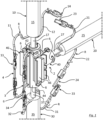
- the fluid line comprises electric heating means positioned around the passage and around ducts 10, 20, 30, so as to heat the fluid through the fluid line.
- Each duct 10, 20, 30 comprises first heating means R and two electric connectors 13, 14, 23, 24, 33, 34 of the male or female type connected to the first heating means R.
- the fluid line there are at least two different types of electric connectors 3, 4, 13, 14, 23, 24, 33, 34, wherein at least one male connector and one female connector, belonging to two different types of electric connectors, cannot be connected to each other.
- no male connector belonging to a first type of connectors can be inserted into a female connector belonging to a second type of connectors.
- a male connector belonging to a first type of connectors can be inserted into a female connector belonging to a second type of connectors, but it is not possible to insert a male connector belonging to a second type of connectors into a female connector belonging to a first type of connectors, e.g. because the connectors of the first type are smaller than the connectors of the second type.
- the electric heating means and in particular the first electric heating means R, are resistors; for example, such resistors comprise, or are, electric wires.
- the first heating means R comprise electric wires or cables 11, 12, 21, 22, 31, 32 connected to, and in particular terminating with, the respective electric connectors 13, 14, 23, 24, 33, 34.
- electric wires 11, 12, 21, 22, 31, 32 are adapted to be connected to an electric current source (not shown) in order to produce heat through the current flowing in such wires, for the purpose of heating ducts 10, 20, 30.
- duct 10, 20, 30 - whereon connector 2 is intended to be mounted - is surrounded, whether internally or externally, by one or more electric heating elements configured to heat up the fluid flowing through said duct.
- the duct 10, 20, 30 comprises an inner tube 17, 27, 37, in which the fluid to be heated is intended to flow.
- Duct 10, 20, 30, in particular inner tube 17, 27, 37 is preferably surrounded by a sheath 15, 25, 35 of electrically and thermally insulating material, e.g. an elastomer (such as thermoplastic rubber), to ensure a higher degree of safety and thermal insulation.
- Inner tubes 17, 27, 37 are inserted into connector 2, in particular into body 8 of connector 2, to effect the fluidic connection for the fluid to be heated.
- Preferred connector 2 illustrated herein comprises a body 8 that defines a passage for the fluid.
- Connector 2, in particular body 8 is configured to fluidically connect at least three ducts 10, 20, 30, which may be, for example, four, five or more as required.
- connector 2 is of the three-way type, since it connects the three ducts 10, 20, 30.
- connector 2, and in particular body 8, is T-shaped.
- Connector 2 comprises body 8, which is preferably thermally conductive.
- Connector 2, in particular the body 8 has a plurality of openings, three in this example, which are adapted to be fluidically connected to respective ducts 10, 20, 30. The passage for the fluid that will flow through connector 2 is defined between such openings.
- an auxiliary heating means is mounted to connector 2, terminating with respective auxiliary electric connectors 3, 4 configured to be connected to electric connectors 13, 14, 23, 24, 33, 34 of ducts 10, 20, 30.
- the auxiliary heating means comprises an auxiliary electric wire 6, which in particular has a first end connected to a first auxiliary electric connector 3 and a second end connected to a second auxiliary electric connector 4.
- the function of the auxiliary heating means is to increase the heating area in contact with connector 2. In other words, it essentially acts as an "extension" of the heating means associated with ducts 10, 20, 30.
- connector 2 comprises a supporting structure 40 positioned around body 8 to support a part of the electric heating means around the passage for the fluid.
- Supporting structure 40 is removably mounted to the body of connector 2. Therefore, supporting structure 40 and the body are two distinct elements of connector 2.
- supporting structure 40 defines a cavity in which body 8 is housed, and the electric heating means, particularly the auxiliary heating means, face, at least partly, towards said cavity. It is thus possible to enhance the heating effect, adding to the advantage of keeping the heating means neatly arranged, particularly when they are provided in the form of wires.
- supporting structure 40 is configured to hold the auxiliary heating means (in the example, auxiliary heating wire 6). Therefore, a part of the electric heating means, i.e.
- Supporting structure 40 comprises fixing means for the electric heating means, e.g. recesses, protrusions, holes, to which part of the electric heating means can be fastened.
- fixing means for the electric heating means e.g. recesses, protrusions, holes, to which part of the electric heating means can be fastened.
- a plurality of recesses are formed in the cavity of supporting structure 40, into which auxiliary electric wire 6 is retained.
- Supporting structure 40 comprises, in particular, an inner surface defining the cavity, the shape of such inner surface being complementary to body 8. On the inner surface fixing means are formed, such as, for example, the recesses that house auxiliary electric wire 6.
- supporting structure 40 comprises two mutually mounted half-bodies 42, 44 allowing supporting structure 40 to be removably assembled on body 8.
- half-bodies 42, 44 are mutually mounted in a movable manner (e.g. by means of a hinge, or a weakened region allowing their mutual rotation).
- Half-bodies 42, 44 are adapted to assume a closed configuration ( Fig. 1 ), in which they are mounted to each other and hold body 8, and an open configuration, in which they permit the removal of body 8.
- half-bodies 42, 44 switch between such two configurations by rotating relative to each other.
- half-bodies 42, 44 are kept in the closed configuration by a closing mechanism, preferably a snap-type mechanism.
- supporting structure 40 comprises a plurality of snap-engaging receptacles 46 (in the example, situated peripherally with respect to supporting structure 40), configured to adapt to an electric connection between two complementary electric connectors 3, 4, 13, 14, 23, 24, 33, 34.
- Receptacles 46 hold such electric connections in position.
- receptacles 46 are arranged on an outer part of supporting structure 40.
- supporting structure 40 is made as one piece with receptacles 46.
- receptacles 46 are adapted to retain shell 39, which is advantageously shaped as a sleeve, of the electric connections.
- supporting structure 40 comprises, preferably on an outer part thereof, fixing means for retaining the connections between complementary electric connectors 3, 4, 13, 14, 23, 24, 33, 34.
- supporting structure 40 comprises one or more clip portions 41 situated on an outer part thereof and configured to retain shells 39.
- supporting structure 40 comprises retaining means for retaining shells 39.
- shell 39 is conveniently electrically insulating, preferably of the heat-shrinking type.
- the fixing of the electric connection between two complementary electric connectors 3, 4, 13, 14, 23, 24, 33, 34 on supporting structure 40 can be accomplished in several ways, e.g. by securing the electric connection, and in particular the respective shell 39, with adhesive tape.
- body 8 has no fixing means for fixing the heating means, in particular the auxiliary heating means consisting, in the example, of the auxiliary heating wire 6.
- Body 8 is simple to manufacture. In the example, the outer surface of body 8 is substantially smooth.
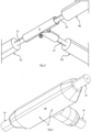
- connector 2 is protected by an external casing 48, which may be either an overmoulded portion ( fig. 3 ), which is moulded over connector 2, or a rigid enclosure ( Fig. 4 ).
- External casing 48 covers the connections between the electric connectors 3, 4, 13, 14, 23, 24, 33, 34, and in particular it also covers the body 8 and the supporting structure 40.
- the external casing 48 shown in Fig. 4 comprises two half-shells 50, 52 mutually mounted in a removable manner.
- the step of connecting electric connectors 13, 14, 23, 24, 33, 34 is followed by a step of enclosing the electric connection of electric connectors 3, 4, 13, 14, 23, 24, 33, 34 in said electrically insulating shell 39, which is preferably of the heat-shrinking type.
- the operator inserts a first electric connector (e.g. 13) into electrically insulating shell 39 (shaped as a sleeve in the example), letting the first electric connector protrude at least partially from said shell 39, then connects the first electric connector to a second electric connector (e.g. 4), and finally inserts the connection between such electric connectors into shell 39.
- the first connector (e.g. 13) and wire 11 associated therewith are run through shell 39. After this step, the two joined electric connectors are within electrically insulating shell 39.
- heat-shrinking shells 39 internally contain (in particular, on an inner surface facing towards the electric connectors) an adhesive or a layer of material to prevent fluids from entering the electric connection region. Therefore, the adhesive has such chemical and/or physical characteristics as to prevent the fluid from entering said connection once the shell has been heated. Due to heating, in fact, the adhesive softens and melts, thus ensuring a proper sealing of the electric connection.
- supporting structure 40 advantageously makes it possible to mount thereon 40 the auxiliary heating means (e.g. auxiliary wire 6) in a separate place (i.e. a place remote from body 8), when ducts 10, 20, 30 have already been fluidically connected to body 8 of connector 2.
- auxiliary heating means e.g. auxiliary wire 6
- connector 2 and in particular half-bodies 42, 44 comprise protrusions 54 (in Figs. 3 and 4 it is possible to see their tips protruding from external casing 48) which allow for repeatable positioning of connector 2 into the mould during the overmoulding process and reduce the movement thereof as the material is injected.
- protrusions 54 may be used for positioning rigid external casing 48 correctly on connector 2 .
Landscapes
- Engineering & Computer Science (AREA)
- Chemical & Material Sciences (AREA)
- Combustion & Propulsion (AREA)
- Mechanical Engineering (AREA)
- General Engineering & Computer Science (AREA)
- Chemical Kinetics & Catalysis (AREA)
- Health & Medical Sciences (AREA)
- Toxicology (AREA)
- Pipe Accessories (AREA)
- Pipeline Systems (AREA)
- Cleaning In General (AREA)
Applications Claiming Priority (2)
| Application Number | Priority Date | Filing Date | Title |
|---|---|---|---|
| IT102019000007010A IT201900007010A1 (it) | 2019-05-20 | 2019-05-20 | Linea per un fluido riscaldabile comprendente più condotti, in particolare per un sistema SCR o un sistema di iniezione ad acqua, e processo di assemblaggio. |
| PCT/IB2020/054673 WO2020234738A1 (en) | 2019-05-20 | 2020-05-18 | Line for a heated fluid comprising more conduits, in particular for an scr system or an injection system for water and assembly process |
Publications (2)
| Publication Number | Publication Date |
|---|---|
| EP3973151A1 EP3973151A1 (en) | 2022-03-30 |
| EP3973151B1 true EP3973151B1 (en) | 2024-07-03 |
Family
ID=67875961
Family Applications (1)
| Application Number | Title | Priority Date | Filing Date |
|---|---|---|---|
| EP20731558.1A Active EP3973151B1 (en) | 2019-05-20 | 2020-05-18 | Line for a heated fluid comprising more conduits, in particular for an scr system or an injection system for water and assembly process |
Country Status (3)
| Country | Link |
|---|---|
| EP (1) | EP3973151B1 (it) |
| IT (1) | IT201900007010A1 (it) |
| WO (1) | WO2020234738A1 (it) |
Family Cites Families (3)
| Publication number | Priority date | Publication date | Assignee | Title |
|---|---|---|---|---|
| DE102016220594A1 (de) * | 2016-10-20 | 2018-04-26 | Contitech Schlauch Gmbh | Verteilerstück für beheizbare Fluidleitungen |
| DE202017101274U1 (de) * | 2017-03-06 | 2017-03-24 | TI Automotive (Fuldabrück) GmbH | Verbindungsaggregat |
| DE202017104371U1 (de) * | 2017-07-21 | 2018-10-23 | Voss Automotive Gmbh | SCR-Verbindungsstelle |
-
2019
- 2019-05-20 IT IT102019000007010A patent/IT201900007010A1/it unknown
-
2020
- 2020-05-18 WO PCT/IB2020/054673 patent/WO2020234738A1/en not_active Ceased
- 2020-05-18 EP EP20731558.1A patent/EP3973151B1/en active Active
Also Published As
| Publication number | Publication date |
|---|---|
| EP3973151A1 (en) | 2022-03-30 |
| IT201900007010A1 (it) | 2020-11-20 |
| WO2020234738A1 (en) | 2020-11-26 |
Similar Documents
| Publication | Publication Date | Title |
|---|---|---|
| US7857645B2 (en) | Connector arrangement for a medium-conducting, electrically-heatable hose | |
| US10851932B2 (en) | Connection unit | |
| US7773865B2 (en) | Assembly for conducting and tempering fluids and method for producing said assembly | |
| JP5091324B2 (ja) | 選択的触媒還元システムのための還元剤供給ユニットのための流体供給接続 | |
| US9890889B2 (en) | Line connector and ready-made media line | |
| CN101346575B (zh) | 加热接头 | |
| CN111226069B (zh) | 用于特别是scr系统或注水系统的可加热流体管道的连接器 | |
| US9353662B2 (en) | Fabricated media line and use in an SCR catalyst system | |
| US8075020B2 (en) | Pipe fitting for a heatable piping of a SCR system | |
| US9598994B2 (en) | Cooling device for connection piece | |
| CN104145095A (zh) | 自动选择性催化还原(scr)系统传感器保持件和组件 | |
| KR101855546B1 (ko) | 엔진 배기가스용 첨가물 저장탱크 | |
| US9587542B2 (en) | Metering module with high-temperature resistance | |
| EP3973151B1 (en) | Line for a heated fluid comprising more conduits, in particular for an scr system or an injection system for water and assembly process | |
| CN103261772B (zh) | 用于介质传导的可电加热软管的可加热连接装置 | |
| WO2007125572A1 (ja) | 配管継手用ヒータ部品 | |
| WO2020234739A1 (en) | System for hydraulically and electrically connecting a plurality of hated ducts configured for carrying an electrically heatable fluid | |
| KR101770376B1 (ko) | 요소수 펌프 모듈 | |
| KR20180078294A (ko) | 배기가스 라인 내로 유체를 계량 주입하기 위한 인젝터 어셈블리 | |
| KR20220087079A (ko) | 일체형 커넥터 유닛 |
Legal Events
| Date | Code | Title | Description |
|---|---|---|---|
| STAA | Information on the status of an ep patent application or granted ep patent |
Free format text: STATUS: UNKNOWN |
|
| STAA | Information on the status of an ep patent application or granted ep patent |
Free format text: STATUS: THE INTERNATIONAL PUBLICATION HAS BEEN MADE |
|
| PUAI | Public reference made under article 153(3) epc to a published international application that has entered the european phase |
Free format text: ORIGINAL CODE: 0009012 |
|
| STAA | Information on the status of an ep patent application or granted ep patent |
Free format text: STATUS: REQUEST FOR EXAMINATION WAS MADE |
|
| 17P | Request for examination filed |
Effective date: 20211214 |
|
| AK | Designated contracting states |
Kind code of ref document: A1 Designated state(s): AL AT BE BG CH CY CZ DE DK EE ES FI FR GB GR HR HU IE IS IT LI LT LU LV MC MK MT NL NO PL PT RO RS SE SI SK SM TR |
|
| DAV | Request for validation of the european patent (deleted) | ||
| DAX | Request for extension of the european patent (deleted) | ||
| P01 | Opt-out of the competence of the unified patent court (upc) registered |
Effective date: 20230509 |
|
| GRAP | Despatch of communication of intention to grant a patent |
Free format text: ORIGINAL CODE: EPIDOSNIGR1 |
|
| STAA | Information on the status of an ep patent application or granted ep patent |
Free format text: STATUS: GRANT OF PATENT IS INTENDED |
|
| INTG | Intention to grant announced |
Effective date: 20240214 |
|
| GRAS | Grant fee paid |
Free format text: ORIGINAL CODE: EPIDOSNIGR3 |
|
| GRAA | (expected) grant |
Free format text: ORIGINAL CODE: 0009210 |
|
| STAA | Information on the status of an ep patent application or granted ep patent |
Free format text: STATUS: THE PATENT HAS BEEN GRANTED |
|
| AK | Designated contracting states |
Kind code of ref document: B1 Designated state(s): AL AT BE BG CH CY CZ DE DK EE ES FI FR GB GR HR HU IE IS IT LI LT LU LV MC MK MT NL NO PL PT RO RS SE SI SK SM TR |
|
| REG | Reference to a national code |
Ref country code: CH Ref legal event code: EP |
|
| REG | Reference to a national code |
Ref country code: DE Ref legal event code: R096 Ref document number: 602020033334 Country of ref document: DE |
|
| REG | Reference to a national code |
Ref country code: LT Ref legal event code: MG9D |
|
| REG | Reference to a national code |
Ref country code: NL Ref legal event code: MP Effective date: 20240703 |
|
| PG25 | Lapsed in a contracting state [announced via postgrant information from national office to epo] |
Ref country code: PT Free format text: LAPSE BECAUSE OF FAILURE TO SUBMIT A TRANSLATION OF THE DESCRIPTION OR TO PAY THE FEE WITHIN THE PRESCRIBED TIME-LIMIT Effective date: 20241104 |
|
| REG | Reference to a national code |
Ref country code: AT Ref legal event code: MK05 Ref document number: 1700027 Country of ref document: AT Kind code of ref document: T Effective date: 20240703 |
|
| PG25 | Lapsed in a contracting state [announced via postgrant information from national office to epo] |
Ref country code: NL Free format text: LAPSE BECAUSE OF FAILURE TO SUBMIT A TRANSLATION OF THE DESCRIPTION OR TO PAY THE FEE WITHIN THE PRESCRIBED TIME-LIMIT Effective date: 20240703 |
|
| PG25 | Lapsed in a contracting state [announced via postgrant information from national office to epo] |
Ref country code: PT Free format text: LAPSE BECAUSE OF FAILURE TO SUBMIT A TRANSLATION OF THE DESCRIPTION OR TO PAY THE FEE WITHIN THE PRESCRIBED TIME-LIMIT Effective date: 20241104 Ref country code: NL Free format text: LAPSE BECAUSE OF FAILURE TO SUBMIT A TRANSLATION OF THE DESCRIPTION OR TO PAY THE FEE WITHIN THE PRESCRIBED TIME-LIMIT Effective date: 20240703 |
|
| PG25 | Lapsed in a contracting state [announced via postgrant information from national office to epo] |
Ref country code: NO Free format text: LAPSE BECAUSE OF FAILURE TO SUBMIT A TRANSLATION OF THE DESCRIPTION OR TO PAY THE FEE WITHIN THE PRESCRIBED TIME-LIMIT Effective date: 20241003 |
|
| PG25 | Lapsed in a contracting state [announced via postgrant information from national office to epo] |
Ref country code: GR Free format text: LAPSE BECAUSE OF FAILURE TO SUBMIT A TRANSLATION OF THE DESCRIPTION OR TO PAY THE FEE WITHIN THE PRESCRIBED TIME-LIMIT Effective date: 20241004 Ref country code: PL Free format text: LAPSE BECAUSE OF FAILURE TO SUBMIT A TRANSLATION OF THE DESCRIPTION OR TO PAY THE FEE WITHIN THE PRESCRIBED TIME-LIMIT Effective date: 20240703 Ref country code: FI Free format text: LAPSE BECAUSE OF FAILURE TO SUBMIT A TRANSLATION OF THE DESCRIPTION OR TO PAY THE FEE WITHIN THE PRESCRIBED TIME-LIMIT Effective date: 20240703 |
|
| PG25 | Lapsed in a contracting state [announced via postgrant information from national office to epo] |
Ref country code: BG Free format text: LAPSE BECAUSE OF FAILURE TO SUBMIT A TRANSLATION OF THE DESCRIPTION OR TO PAY THE FEE WITHIN THE PRESCRIBED TIME-LIMIT Effective date: 20240703 |
|
| PG25 | Lapsed in a contracting state [announced via postgrant information from national office to epo] |
Ref country code: LV Free format text: LAPSE BECAUSE OF FAILURE TO SUBMIT A TRANSLATION OF THE DESCRIPTION OR TO PAY THE FEE WITHIN THE PRESCRIBED TIME-LIMIT Effective date: 20240703 |
|
| PG25 | Lapsed in a contracting state [announced via postgrant information from national office to epo] |
Ref country code: AT Free format text: LAPSE BECAUSE OF FAILURE TO SUBMIT A TRANSLATION OF THE DESCRIPTION OR TO PAY THE FEE WITHIN THE PRESCRIBED TIME-LIMIT Effective date: 20240703 Ref country code: IS Free format text: LAPSE BECAUSE OF FAILURE TO SUBMIT A TRANSLATION OF THE DESCRIPTION OR TO PAY THE FEE WITHIN THE PRESCRIBED TIME-LIMIT Effective date: 20241103 |
|
| PG25 | Lapsed in a contracting state [announced via postgrant information from national office to epo] |
Ref country code: HR Free format text: LAPSE BECAUSE OF FAILURE TO SUBMIT A TRANSLATION OF THE DESCRIPTION OR TO PAY THE FEE WITHIN THE PRESCRIBED TIME-LIMIT Effective date: 20240703 Ref country code: CZ Free format text: LAPSE BECAUSE OF FAILURE TO SUBMIT A TRANSLATION OF THE DESCRIPTION OR TO PAY THE FEE WITHIN THE PRESCRIBED TIME-LIMIT Effective date: 20240703 |
|
| PG25 | Lapsed in a contracting state [announced via postgrant information from national office to epo] |
Ref country code: ES Free format text: LAPSE BECAUSE OF FAILURE TO SUBMIT A TRANSLATION OF THE DESCRIPTION OR TO PAY THE FEE WITHIN THE PRESCRIBED TIME-LIMIT Effective date: 20240703 Ref country code: RS Free format text: LAPSE BECAUSE OF FAILURE TO SUBMIT A TRANSLATION OF THE DESCRIPTION OR TO PAY THE FEE WITHIN THE PRESCRIBED TIME-LIMIT Effective date: 20241003 |
|
| PG25 | Lapsed in a contracting state [announced via postgrant information from national office to epo] |
Ref country code: RS Free format text: LAPSE BECAUSE OF FAILURE TO SUBMIT A TRANSLATION OF THE DESCRIPTION OR TO PAY THE FEE WITHIN THE PRESCRIBED TIME-LIMIT Effective date: 20241003 Ref country code: PL Free format text: LAPSE BECAUSE OF FAILURE TO SUBMIT A TRANSLATION OF THE DESCRIPTION OR TO PAY THE FEE WITHIN THE PRESCRIBED TIME-LIMIT Effective date: 20240703 Ref country code: NO Free format text: LAPSE BECAUSE OF FAILURE TO SUBMIT A TRANSLATION OF THE DESCRIPTION OR TO PAY THE FEE WITHIN THE PRESCRIBED TIME-LIMIT Effective date: 20241003 Ref country code: LV Free format text: LAPSE BECAUSE OF FAILURE TO SUBMIT A TRANSLATION OF THE DESCRIPTION OR TO PAY THE FEE WITHIN THE PRESCRIBED TIME-LIMIT Effective date: 20240703 Ref country code: IS Free format text: LAPSE BECAUSE OF FAILURE TO SUBMIT A TRANSLATION OF THE DESCRIPTION OR TO PAY THE FEE WITHIN THE PRESCRIBED TIME-LIMIT Effective date: 20241103 Ref country code: HR Free format text: LAPSE BECAUSE OF FAILURE TO SUBMIT A TRANSLATION OF THE DESCRIPTION OR TO PAY THE FEE WITHIN THE PRESCRIBED TIME-LIMIT Effective date: 20240703 Ref country code: GR Free format text: LAPSE BECAUSE OF FAILURE TO SUBMIT A TRANSLATION OF THE DESCRIPTION OR TO PAY THE FEE WITHIN THE PRESCRIBED TIME-LIMIT Effective date: 20241004 Ref country code: FI Free format text: LAPSE BECAUSE OF FAILURE TO SUBMIT A TRANSLATION OF THE DESCRIPTION OR TO PAY THE FEE WITHIN THE PRESCRIBED TIME-LIMIT Effective date: 20240703 Ref country code: ES Free format text: LAPSE BECAUSE OF FAILURE TO SUBMIT A TRANSLATION OF THE DESCRIPTION OR TO PAY THE FEE WITHIN THE PRESCRIBED TIME-LIMIT Effective date: 20240703 Ref country code: CZ Free format text: LAPSE BECAUSE OF FAILURE TO SUBMIT A TRANSLATION OF THE DESCRIPTION OR TO PAY THE FEE WITHIN THE PRESCRIBED TIME-LIMIT Effective date: 20240703 Ref country code: BG Free format text: LAPSE BECAUSE OF FAILURE TO SUBMIT A TRANSLATION OF THE DESCRIPTION OR TO PAY THE FEE WITHIN THE PRESCRIBED TIME-LIMIT Effective date: 20240703 Ref country code: AT Free format text: LAPSE BECAUSE OF FAILURE TO SUBMIT A TRANSLATION OF THE DESCRIPTION OR TO PAY THE FEE WITHIN THE PRESCRIBED TIME-LIMIT Effective date: 20240703 |
|
| REG | Reference to a national code |
Ref country code: DE Ref legal event code: R097 Ref document number: 602020033334 Country of ref document: DE |
|
| PG25 | Lapsed in a contracting state [announced via postgrant information from national office to epo] |
Ref country code: SM Free format text: LAPSE BECAUSE OF FAILURE TO SUBMIT A TRANSLATION OF THE DESCRIPTION OR TO PAY THE FEE WITHIN THE PRESCRIBED TIME-LIMIT Effective date: 20240703 Ref country code: DK Free format text: LAPSE BECAUSE OF FAILURE TO SUBMIT A TRANSLATION OF THE DESCRIPTION OR TO PAY THE FEE WITHIN THE PRESCRIBED TIME-LIMIT Effective date: 20240703 Ref country code: RO Free format text: LAPSE BECAUSE OF FAILURE TO SUBMIT A TRANSLATION OF THE DESCRIPTION OR TO PAY THE FEE WITHIN THE PRESCRIBED TIME-LIMIT Effective date: 20240703 |
|
| PG25 | Lapsed in a contracting state [announced via postgrant information from national office to epo] |
Ref country code: EE Free format text: LAPSE BECAUSE OF FAILURE TO SUBMIT A TRANSLATION OF THE DESCRIPTION OR TO PAY THE FEE WITHIN THE PRESCRIBED TIME-LIMIT Effective date: 20240703 |
|
| PG25 | Lapsed in a contracting state [announced via postgrant information from national office to epo] |
Ref country code: SK Free format text: LAPSE BECAUSE OF FAILURE TO SUBMIT A TRANSLATION OF THE DESCRIPTION OR TO PAY THE FEE WITHIN THE PRESCRIBED TIME-LIMIT Effective date: 20240703 |
|
| PLBE | No opposition filed within time limit |
Free format text: ORIGINAL CODE: 0009261 |
|
| STAA | Information on the status of an ep patent application or granted ep patent |
Free format text: STATUS: NO OPPOSITION FILED WITHIN TIME LIMIT |
|
| 26N | No opposition filed |
Effective date: 20250404 |
|
| PGFP | Annual fee paid to national office [announced via postgrant information from national office to epo] |
Ref country code: DE Payment date: 20250325 Year of fee payment: 6 |
|
| PG25 | Lapsed in a contracting state [announced via postgrant information from national office to epo] |
Ref country code: SE Free format text: LAPSE BECAUSE OF FAILURE TO SUBMIT A TRANSLATION OF THE DESCRIPTION OR TO PAY THE FEE WITHIN THE PRESCRIBED TIME-LIMIT Effective date: 20240703 |
|
| REG | Reference to a national code |
Ref country code: CH Ref legal event code: H13 Free format text: ST27 STATUS EVENT CODE: U-0-0-H10-H13 (AS PROVIDED BY THE NATIONAL OFFICE) Effective date: 20251223 |
|
| PG25 | Lapsed in a contracting state [announced via postgrant information from national office to epo] |
Ref country code: LU Free format text: LAPSE BECAUSE OF NON-PAYMENT OF DUE FEES Effective date: 20250518 |
|
| PG25 | Lapsed in a contracting state [announced via postgrant information from national office to epo] |
Ref country code: CH Free format text: LAPSE BECAUSE OF NON-PAYMENT OF DUE FEES Effective date: 20250531 |
|
| GBPC | Gb: european patent ceased through non-payment of renewal fee |
Effective date: 20250518 |
|
| REG | Reference to a national code |
Ref country code: BE Ref legal event code: MM Effective date: 20250531 |
|
| PG25 | Lapsed in a contracting state [announced via postgrant information from national office to epo] |
Ref country code: MC Free format text: LAPSE BECAUSE OF FAILURE TO SUBMIT A TRANSLATION OF THE DESCRIPTION OR TO PAY THE FEE WITHIN THE PRESCRIBED TIME-LIMIT Effective date: 20240703 |
|
| PG25 | Lapsed in a contracting state [announced via postgrant information from national office to epo] |
Ref country code: GB Free format text: LAPSE BECAUSE OF NON-PAYMENT OF DUE FEES Effective date: 20250518 |
|
| PG25 | Lapsed in a contracting state [announced via postgrant information from national office to epo] |
Ref country code: IE Free format text: LAPSE BECAUSE OF NON-PAYMENT OF DUE FEES Effective date: 20250518 |
|
| PG25 | Lapsed in a contracting state [announced via postgrant information from national office to epo] |
Ref country code: BE Free format text: LAPSE BECAUSE OF NON-PAYMENT OF DUE FEES Effective date: 20250531 |
|
| PGFP | Annual fee paid to national office [announced via postgrant information from national office to epo] |
Ref country code: IT Payment date: 20260204 Year of fee payment: 7 |
|
| PGFP | Annual fee paid to national office [announced via postgrant information from national office to epo] |
Ref country code: FR Payment date: 20260309 Year of fee payment: 7 |