EP3973176B1 - Turbinenvorrichtung - Google Patents
Turbinenvorrichtung Download PDFInfo
- Publication number
- EP3973176B1 EP3973176B1 EP20732734.7A EP20732734A EP3973176B1 EP 3973176 B1 EP3973176 B1 EP 3973176B1 EP 20732734 A EP20732734 A EP 20732734A EP 3973176 B1 EP3973176 B1 EP 3973176B1
- Authority
- EP
- European Patent Office
- Prior art keywords
- turbine device
- unit
- front edge
- impeller vane
- objects
- Prior art date
- Legal status (The legal status is an assumption and is not a legal conclusion. Google has not performed a legal analysis and makes no representation as to the accuracy of the status listed.)
- Active
Links
Images


Classifications
-
- F—MECHANICAL ENGINEERING; LIGHTING; HEATING; WEAPONS; BLASTING
- F03—MACHINES OR ENGINES FOR LIQUIDS; WIND, SPRING, OR WEIGHT MOTORS; PRODUCING MECHANICAL POWER OR A REACTIVE PROPULSIVE THRUST, NOT OTHERWISE PROVIDED FOR
- F03B—MACHINES OR ENGINES FOR LIQUIDS
- F03B3/00—Machines or engines of reaction type; Parts or details peculiar thereto
- F03B3/12—Blades; Blade-carrying rotors
- F03B3/121—Blades, their form or construction
-
- E—FIXED CONSTRUCTIONS
- E02—HYDRAULIC ENGINEERING; FOUNDATIONS; SOIL SHIFTING
- E02B—HYDRAULIC ENGINEERING
- E02B9/00—Water-power plants; Layout, construction or equipment, methods of, or apparatus for, making same
- E02B9/02—Water-ways
- E02B9/06—Pressure galleries or pressure conduits; Galleries specially adapted to house pressure conduits; Means specially adapted for use therewith, e.g. housings, valves, gates
-
- F—MECHANICAL ENGINEERING; LIGHTING; HEATING; WEAPONS; BLASTING
- F05—INDEXING SCHEMES RELATING TO ENGINES OR PUMPS IN VARIOUS SUBCLASSES OF CLASSES F01-F04
- F05B—INDEXING SCHEME RELATING TO WIND, SPRING, WEIGHT, INERTIA OR LIKE MOTORS, TO MACHINES OR ENGINES FOR LIQUIDS COVERED BY SUBCLASSES F03B, F03D AND F03G
- F05B2240/00—Components
- F05B2240/20—Rotors
- F05B2240/24—Rotors for turbines
- F05B2240/242—Rotors for turbines of reaction type
-
- F—MECHANICAL ENGINEERING; LIGHTING; HEATING; WEAPONS; BLASTING
- F05—INDEXING SCHEMES RELATING TO ENGINES OR PUMPS IN VARIOUS SUBCLASSES OF CLASSES F01-F04
- F05B—INDEXING SCHEME RELATING TO WIND, SPRING, WEIGHT, INERTIA OR LIKE MOTORS, TO MACHINES OR ENGINES FOR LIQUIDS COVERED BY SUBCLASSES F03B, F03D AND F03G
- F05B2240/00—Components
- F05B2240/20—Rotors
- F05B2240/30—Characteristics of rotor blades, i.e. of any element transforming dynamic fluid energy to or from rotational energy and being attached to a rotor
-
- Y—GENERAL TAGGING OF NEW TECHNOLOGICAL DEVELOPMENTS; GENERAL TAGGING OF CROSS-SECTIONAL TECHNOLOGIES SPANNING OVER SEVERAL SECTIONS OF THE IPC; TECHNICAL SUBJECTS COVERED BY FORMER USPC CROSS-REFERENCE ART COLLECTIONS [XRACs] AND DIGESTS
- Y02—TECHNOLOGIES OR APPLICATIONS FOR MITIGATION OR ADAPTATION AGAINST CLIMATE CHANGE
- Y02E—REDUCTION OF GREENHOUSE GAS [GHG] EMISSIONS, RELATED TO ENERGY GENERATION, TRANSMISSION OR DISTRIBUTION
- Y02E10/00—Energy generation through renewable energy sources
- Y02E10/20—Hydro energy
Definitions
- the invention relates to a turbine device according to the preamble of claim 1, a hydroelectric power plant according to claim 12 with a corresponding turbine device, and a method for designing a hydroelectric power plant according to claim 13.
- the pamphlet EP 2 295 808 A2 discloses a turbine device with stator blades which are inclined at a shallow angle to avoid injuring fish.
- the object of the invention consists in particular in providing a generic device with improved properties with regard to safety, in particular fish-friendliness, in particular while at least largely maintaining efficiency.
- the object is achieved according to the invention by the features of patent claims 1 and 13, while advantageous configurations and developments of the invention can be found in the dependent claims.
- the invention is based on a turbine device, in particular a Kaplan, tubular and/or straflo turbine device, with at least one line unit for conducting at least one fluid flow and with at least one impeller blade unit arranged within the line unit and rotatable about an axis of rotation, which has at least one impeller blade, wherein the turbine device has a protection unit which is intended to urge objects flowing in the fluid flow in at least one operating state, in particular flotsam and preferably fish, in particular eels, in the direction of the axis of rotation.
- a safe and/or fish-friendly design of the impeller blade can be concentrated on a partial area of the impeller blade that is closest to the axis of rotation.
- a “turbine device” is to be understood in particular as a device which is intended to convert kinetic energy of a fluid, in particular water, into rotational energy, in particular of a shaft of the turbine device.
- the kinetic energy is preferably created by converting a potential energy of the fluid.
- a flow direction of the fluid flow advantageously runs at least partially along a direction of gravity.
- the line unit defines the flow direction of the fluid flow.
- a “conduit unit” is to be understood in particular as a unit which is provided for guiding the fluid flow.
- the line unit preferably has at least one, in particular tubular, line element.
- the line unit preferably has at least one inlet and one outlet, between which the impeller vane unit is arranged.
- a flow direction of the fluid flow between the inlet and the outlet can vary continuously and/or abruptly.
- An “impeller vane unit” is to be understood in particular as a unit which is intended to experience a rotational movement caused by fluid flowing past in the operating state.
- the impeller blade unit is preferably functionally connected to at least one generator unit of the turbine device, which generates rotational energy of the impeller blade unit converted into electrical energy.
- the turbine device has at least one shaft which defines the axis of rotation.
- the impeller vane unit advantageously has at least one impeller vane hub fastened to the shaft.
- the impeller blade hub carries the impeller blade.
- the impeller blade can be rotatable relative to the impeller blade hub.
- the impeller blade could also be firmly connected to the impeller blade hub.
- the impeller blade preferably has at least one mounting element, which enables the impeller blade to be mounted on the impeller blade hub and/or defines an adjustment axis of rotation of the impeller blade relative to the impeller blade hub.
- the impeller blade unit can have at least one blade ring, which surrounds all the impeller blades of the impeller blade unit, in particular when viewed along the axis of rotation. In particular, the blade ring is in contact with the outer edges of all impeller blades.
- the impeller blade has in particular at least one blade leaf, which preferably has leaf areas lying opposite one another, in particular with respect to the adjustment axis of rotation.
- a “blade area” is to be understood in this context in particular as a part of the airfoil that is different from a pure surface and has at least 20%, advantageously at least 30% and preferably at least 40% of a volume of the airfoil. In particular, both blade areas can form the entire airfoil.
- the first blade area forms a front side of the impeller blade and the second blade area forms a rear side of the impeller blade.
- a “front side” is to be understood in particular as meaning a part of the airfoil which is arranged closer to the inlet of the line unit than a rear side.
- the airfoil has two opposite main surfaces, which are preferably jointly defined by both blade areas.
- a "main surface of the impeller blade” is to be understood in particular as a surface which defines one side of the blade airfoil.
- the impeller blade at least two opposing main surfaces. It would be conceivable for the two blade areas to be axially symmetrical to one another, in particular axially symmetrical to the adjustment axis of rotation.
- the airfoil has at least one outer edge, which preferably defines a common outer edge of both blade areas.
- the front side has at least one front edge opposite the outer edge.
- the rear has at least one rear edge opposite the outer edge.
- the outer edge can in particular be designed as a continuous edge.
- the outer edge could be interrupted by at least one stabilizing element of the impeller blade.
- a “stabilization element” is to be understood in particular as a part of the impeller blade which is intended to stabilize the impeller blade in an operating state, preferably during a rotation of the impeller blade.
- the stabilizing element is particularly preferably configured in one piece with the airfoil.
- the blade areas, the mounting element and the stabilizing element are formed in one piece with one another.
- In one piece is to be understood in particular as being at least cohesively connected, for example by a welding process, an adhesive process, a spraying process and/or another process that appears sensible to the person skilled in the art, and/or advantageously formed in one piece, such as by production from a single cast and/or by production in a one-component or multi-component injection molding process and advantageously from a single blank.
- the turbine device is preferably designed as a Kaplan turbine device.
- a “Kaplan turbine device” is to be understood in particular as a turbine device in which the direction of flow of fluid impinging on the impeller blade runs at least approximately parallel to the axis of rotation. “At least approximately” is to be understood here in particular as meaning that the direction of flow and the axis of rotation together form an angle of at most 40°, advantageously at most 35°, advantageously at most 30° and it is particularly advantageous to open it by a maximum of 25°.
- the impeller blade of the Kaplan turbine device is preferably designed to be adjustable.
- the objects can preferably include objects that occur naturally within bodies of water, such as aquatic plants and/or aquatic creatures, in particular fish, in particular eels, and/or crabs and/or mussels. It would also be conceivable for the objects to have foodstuffs and/or land plants and/or land-dwelling creatures.
- the protection unit is preferably free of sharp edges at least in an area that can be reached by the objects.
- the protective unit is advantageously free of abutment surfaces which run perpendicularly to a direction of movement of the objects. Particularly advantageously, the protection unit brings about a continuous movement of the objects in the direction of the axis of rotation. It would be conceivable for the protective unit to be at least partially detachably mounted on a remaining turbine device.
- the protection unit is intended to direct the flowing objects radially towards the axis of rotation.
- the protection unit preferably guides the flowing objects radially towards the axis of rotation by means of a shape of the protection unit.
- the protective unit has partial areas which, when the flowing objects come into contact with the partial areas, allow the objects to slide off radially towards the axis of rotation.
- the protection unit advantageously has at least one deflection element which is provided for deflecting a direction of movement of the objects.
- the deflection element is designed as a mechanical element.
- the deflection element prefferably be embodied as a rail, which is in particular embodied separately from the impeller blade unit and directs the flowing objects radially to the axis of rotation before they come into contact with the impeller blade unit.
- a gentle and easy-to-implement movement of the flowing objects can be reached radially to the axis of rotation.
- damage to the flowing objects caused by the movement of the flowing objects radially to the axis of rotation can be avoided.
- the movement of the flowing objects radially to the axis of rotation can be achieved particularly advantageously without significant additional energy consumption and/or a significant deterioration in the efficiency of the turbine device.
- the guard assembly is at least partially integral with the impeller vane assembly.
- the fact that two units are formed "at least partially in one piece" with one another is to be understood in this context in particular as meaning that the two units have at least one common element.
- the protection unit is preferably formed at least partially in one piece with the impeller blade. In this way, in particular, a compact and robust configuration of the protective unit can be achieved. Advantageously, space can be saved in comparison to a separately designed protective unit. A detachment and/or displacement of the protection unit during operation of the turbine device can be avoided in a particularly advantageous manner.
- the protection unit has at least one contour element of the impeller blade.
- a “contour element” is to be understood in particular as an element of an object which, looking at the object along a predefined viewing direction, at least partially defines an outer contour of the object.
- the predefined viewing direction onto the contour element is preferably perpendicular to a main surface of the impeller blade.
- the fact that the contour element "at least partially defines" the outer contour of the object when viewed along the viewing direction should be understood in this context to mean in particular that the contour element, when viewed along the viewing direction, defines the outer contour of the object by at least 10%, advantageously at least 20% and particularly advantageously by at least 30%.
- the contour element has at least one edge of the rotor blade.
- edge is to be understood in particular as a surface area of the impeller blade which covers the main surfaces of the Airfoil connects.
- the edge could be smooth or rounded.
- protection of the flowing objects can be improved.
- damage to the flowing objects by the impeller blades can be avoided.
- the contour element forms at least partially, advantageously to a large extent and preferably completely a front edge of the impeller blade.
- a gentle design of the front edge which is particularly dangerous for flowing objects in the prior art, can be achieved. Cutting the objects due to a rotational movement of the front edge can advantageously be avoided.
- the front edge is at least essentially crescent-shaped. “At least essentially” should be understood in particular to mean that a difference is within common manufacturing tolerances.
- the fact that the front edge of the impeller blade is “sickle-shaped” should be understood to mean in particular that the front edge has a curvature and at least one end of the edge meets another end of another edge, in particular the outer edge, of the impeller blade with a further curvature and contributes to the formation of a point.
- a “curvature” is to be understood in particular as meaning a local change in a direction of progression, in particular during a movement from the first end of the front edge to the second end of the front edge.
- an “end” is to be understood in particular as a partial area of the front edge which delimits the front edge outwards along a direction in which the front edge extends and whose length is at most 20%, advantageously at most 15%, preferably at most 10% and particularly preferably at most 5% of a length of the front edge.
- a “tip” is to be understood in particular as a partial area of a body which delimits the body in at least one outward direction and has a shape that tapers along the direction. The tip is preferred oriented away from the axis of rotation.
- a leaf area having the leading edge is designed as a sickle.
- the front edge is arc-shaped when viewed at least perpendicularly onto at least one main surface of the impeller blade.
- a "perpendicular view of a surface” is to be understood in particular as a viewing direction that forms a right angle with a point on the surface that it intersects.
- the perpendicular viewing of the surface can be dependent on a point of the surface being viewed.
- an “arcuate front edge” is to be understood in particular as an edge which has a curvature that extends over the entire edge and is preferably continuously variable.
- the leading edge is preferably curved towards the axis of rotation. In this way, in particular, guiding of the flowing objects to the axis of rotation can be improved.
- projections and/or protruding tips and/or corners of the leading edge which could damage the flowing objects, can be avoided.
- the front edge in at least one working position of the impeller vane unit pierces a plane running perpendicular to the axis of rotation at at least one intersection point, which is radially non-uniformly displaced during an imaginary movement of the plane parallel to the axis of rotation.
- the imaginary movement of the plane at least essentially describes a movement of the flowing objects.
- the point of intersection shifts in the direction of the axis of rotation.
- the point of intersection preferably shifts at a constant speed of movement of the plane with a speed of movement that increases, in particular continuously, increasing. In this way, in particular, a gentle guidance of the flowing objects to the axis of rotation can be achieved. Guiding of the flowing objects to the axis of rotation can advantageously be ensured before the flowing objects pass the front part. Particularly advantageously, damage to the flowing objects can be avoided by directing the flowing objects too abruptly.
- a direction of movement of the point rotates by at least 70°, in particular at least 120°, advantageously at least 170°, preferably at least 220° and particularly preferably at least 270° in one direction.
- a first end of the leading edge is oriented substantially perpendicular to the axis of rotation.
- a second end of the leading edge contributes to the formation of the tip.
- a maximum vertical distance between a connecting line between two end points of the front edge and any other points on the front edge is at least 15%, advantageously at least 25%, preferably at least 35% and particularly preferably at least 45% of a length of the connecting line.
- the distance advantageously defines a local movement speed of the point of intersection with respect to the axis of rotation.
- the leading edge has a curve which connects at least one first main surface of the impeller blade to at least one opposite second main surface of the impeller blade.
- the rounding forms a concave partial area of the impeller blade.
- a maximum vertical distance between a connecting line between two end points of the curve and any other points of the curve is advantageously at most 40%, advantageously at most 35%, preferably at most 30% and particularly preferably at most 25% of a length of the connecting line.
- the perpendicular distance preferably decreases radially in the direction of the axis of rotation.
- a thickness of the front edge increases radially in the direction of the axis of rotation, preferably continuously.
- the rounding of the leading edge flattens out in proportion to a thickness of the leading edge.
- the front edge is preferably flush with the mounting element. In this way, in particular, damage to the flowing objects near the axis of rotation can be avoided in a simple manner.
- impact forces can be distributed over a higher surface in the event of an impact of the flowing objects on an end region of the front edge facing the axis of rotation.
- the thickness preferably increases radially in the direction of the axis of rotation by at least 200%, advantageously at least 400%, preferably at least 600% and particularly preferably at least 800%. In this way, in particular, damage to the flowing objects near the axis of rotation can be avoided even better.
- the rounding of the front edge can be made sufficiently flat to prevent the flowing objects from being severed by the front edge.
- the impeller blade be designed asymmetrical in terms of rotation.
- the fact that a body is "rotationally asymmetrical" is to be understood in particular as meaning that the body is free of rotational symmetries with respect to any axis of rotation.
- both sheet areas are free of rotational symmetries with respect to one another.
- the second blade region has a trailing edge that runs at least substantially in a straight line when viewed perpendicularly to the main surface of the impeller blade.
- a design of a trailing edge that does not touch the flowing objects anyway, with increased safety, can be dispensed with.
- the further blade area having the trailing edge can instead be designed for optimal energy generation.
- the protection unit has at least one shielding element, which is provided to at least make it more difficult for objects to penetrate into an area between a radial outside of the impeller blade and at least one wall of the line unit.
- the shielding element can be provided to cover a region between a radial outside of the impeller blade and at least one wall of the line unit when viewed along the axis of rotation.
- the fact that the shielding element “covers” the area is to be understood in particular to mean that the shielding element impedes and preferably prevents a movement of the flowing objects into the area.
- a "radial outside” is to be understood in particular as a side of the impeller blade which faces away from the axis of rotation.
- the outer edge of the impeller blade defines the radially outer side of the impeller blade.
- the blade ring could make it more difficult for the objects to penetrate into the area between the radial outside and the wall. In this way, in particular, the security of the outer edge can be increased.
- damage to the flowing objects can be avoided by the outer edge.
- the shielding element could be designed as a separate additional element fastened to the line unit.
- the shielding element is preferably formed at least partially in one piece with the line unit and is preferably formed as a recess in the line unit.
- the shielding element connects a first partial area of the line unit facing the inlet to the wall, which is in particular part of a second partial area of the line unit facing the outlet.
- the wall and/or the second partial area can have a diameter that is higher than and/or essentially identical to a first diameter of the first partial area.
- a value and/or an element is "at least essentially identical" to another value and/or element is to be understood in particular as meaning that the value and/or the element has a deviation of at most 20%, advantageously at most 15%, preferably at most 10% and particularly preferably at most 5% with regard to the value and/or a shape of the further element.
- the wall can have a rectilinear and/or curved course. As a result, the security of the outer edge can be increased in a particularly simple manner. Additional assembly steps for fastening the shielding element can advantageously be dispensed with.
- a hydroelectric power station in particular with increased protection of objects flowing in a fluid flow, with a turbine device according to the invention is proposed.
- the safety of objects flowing through the hydroelectric power station in particular flotsam and preferably fish, in particular eels, can be increased.
- the invention is based on a method for designing a hydroelectric power station, in particular with increased protection of objects flowing in a fluid flow.
- a reduction in efficiency due to the use of a turbine device according to the invention is at least compensated for by dispensing with at least one further protective measure for objects flowing in the fluid flow.
- the protective measures include, for example, using flotsam rakes and/or reducing the bar spacing of flotsam rakes. In this way, in particular, the efficiency of the hydroelectric power station can be increased while the hydroelectric power station is highly reliable.
- the turbine device according to the invention should not be limited to the application and embodiment described above.
- the turbine device according to the invention can have a number of individual elements, components and units that differs from a number specified here in order to fulfill a function described herein.
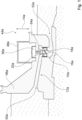
- the hydroelectric power plant 44a has increased protection from objects (not shown) flowing in a fluid flow (not shown).
- the hydroelectric power plant 44a has a dam 46a.
- the hydroelectric power station 44a has a machine house 48a.
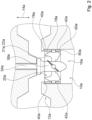
- the hydroelectric power station 44a has a turbine device 10a. Part of the turbine device 10a is in figure 2 shown in more detail.
- the turbine device 10a is designed as a Kaplan turbine device. Alternatively, the turbine device 10a could also be in the form of a bulb turbine device and/or a penal turbine device.
- the turbine device 10a has a line unit 12a.
- the piping unit 12a is provided for piping the fluid flow.
- the line unit 12a is designed as a pipe system.
- the line unit 12a has an inlet opening 50a.
- the line unit 12a has an outlet opening 52a.
- the input port 50a and the output port 52a together define a direction of fluid flow. Fluid flow is from input port 50a to output port 52a.
- the turbine device 10a has an impeller vane unit 16a.
- the impeller vane unit 16a is arranged inside the duct unit 12a.
- the impeller vane unit 16a is rotatable about an axis of rotation 14a.
- the axis of rotation 14a is aligned parallel to a direction of gravity.
- the impeller vane unit 16a has an impeller vane hub 58a.
- the impeller blade unit 16a has four impeller blades which are identical to one another, which is why only one impeller blade 18a is given a reference number and is described below.
- the impeller blade unit 16a could also have any other number of impeller blades.
- the impeller blade 18a is rotatably connected to the impeller blade hub 58a. The impeller blade 18a is in a working position.
- the impeller blade unit 16a has a blade ring 80a.
- the blade ring 80a surrounds the impeller blade 18a when viewed along the axis of rotation 14a.
- the blade ring 80a has recesses.
- the impeller blade 18a has a stabilizing element 72a.
- the stabilizing element 72a is intended to support the impeller blade 18a during rotation of the impeller blade 18a to stabilize.
- the stabilizing element 72a engages in one of the recesses of the vane ring 80a.
- the impeller vane assembly 16a is fixedly attached to a shaft 54a.
- the shaft 54a is operatively connected to a generator 56a.
- the generator 56a is arranged in the machine house 48a. In one operating condition, fluid flow rotates the impeller vane assembly 16a.
- the impeller vane unit 16a imparts the rotation to the shaft 54a.
- the generator 56a generates electricity using the rotation of the shaft 54a.
- the turbine device 10a has a protection unit 20a.
- the protection unit 20a is intended to urge objects flowing in the fluid flow in the direction towards the axis of rotation 14a in the operating state.
- the protection unit 20a is intended to direct the flowing objects radially towards the axis of rotation 14a.
- the protective unit 20a could also merely prevent objects flowing in the vicinity of the axis of rotation 14a from moving counter to the axis of rotation 14a.
- the protection unit 20a is formed at least partially in one piece with the impeller vane unit 16a.
- the protection unit 20a has a contour element 21a of the impeller blade 18a.
- the contour element 21a completely forms a front edge 22a of the impeller blade 18a.
- the contour element 21a could only form part of the front edge 22a.
- the protective unit 20a has two shielding elements 40a which are identical to one another, which is why only one of the shielding elements 40a is described below.
- the shielding element 40a is provided to at least make it more difficult for objects to penetrate into an area between a radial outside of the impeller blade 18a and at least one wall 42a of the line unit 12a.
- the shielding element 40a is formed in one piece with the line unit 12a.
- the shielding element 40a could be designed as a separate element and attached to the line unit 12a.
- the shielding element 40a connects an outer portion 78a to the wall 42a.
- the wall 42a has a higher diameter than the outer portion 78a.
- the wall 42a is straight.
- the wall 42a could be curved.
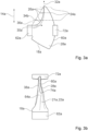
- the Figures 3a to 3e show different schematic representations of the impeller blade 18a.
- the impeller blade 18a has a mounting element 62a.
- Mounting member 62a helps secure impeller blade 18a to impeller blade hub 58a.
- the mounting member 62a is located entirely within the impeller blade hub 58a in an assembled condition.
- the impeller blade 18a has an airfoil 64a.
- the airfoil 64a has a first major surface 28a and a second major surface 38a.
- the main surfaces 28a, 38a are arranged opposite one another.
- the impeller blade 18a has an outer edge 60a.
- the outer edge 60a connects both main surfaces 28a, 38a to one another.
- the outer edge 60a defines the radially outer side of the impeller blade 18a.
- Airfoil 64a includes a first blade portion 66a and a second blade portion 68a. Outer edge 60 defines a common edge of both sheet portions 66a, 68a.
- the impeller blade 18a is rotationally asymmetrical.
- the first sheet portion 66a and the second sheet portion 68a are formed differently from each other. Alternatively, both sheet areas 66a, 68a could also be configured identically to one another.
- the first sheet portion 66a has a trailing edge 70a which is substantially straight when viewed perpendicularly to the major surfaces 28a, 38a.
- the second sheet portion 68a has a leading edge 22a.
- the front edge 22a is formed in an arc shape. Alternatively, the front edge 22a could also have corners and/or several different directions of curvature.
- the leading edge 22a is crescent-shaped.
- the leading edge 22a meets the outer edge 60a at a point 74a.
- the second leaf portion 68a is formed as a sickle.
- the front edge 22a penetrates a plane 24a running perpendicularly to the axis of rotation 14a at an intersection 26a.
- the point of intersection 26a shifts with an imaginary movement the plane 24a parallel to the axis of rotation 14a radially non-uniformly in the direction of the axis of rotation 14a.
- the point of intersection 26a could shift uniformly.
- a direction of movement of the point rotates by approximately 80°.
- the direction of movement of the point could rotate 100° or 200°.
- a first direction of movement 30a of the point at the end of the leading edge 22a and a second direction of movement 32a of the point at the further end of the leading edge 22a together span an angle of approximately 80°.
- a maximum perpendicular distance 34a between a connecting line 36a of two end points of the leading edge 22a and any other points of the leading edge 22a is approximately 40% of a length of the connecting line 36a.
- the perpendicular distance 34a could be 60% or 80% of a length of the connecting line 36a.
- the front edge 22a has a rounding.
- the rounding connects the first main surface 28a of the impeller blade 18a to the second main surface 38a of the impeller blade 18a.
- a thickness of the leading edge 22a increases radially in the direction of the axis of rotation 14a.
- the rounding flattens out in proportion to the increase in thickness of the leading edge 22a.
- the thickness of the leading edge 22a increases radially in the direction of the axis of rotation 14a by approximately 1000%.
- the leading edge 22a could increase in thickness radially toward the axis of rotation 14a by about 200% or 1200%.
- FIG 4 a schematic process diagram of a method for designing the hydroelectric power plant 44a is shown.
- the hydroelectric power plant 44a is equipped with the turbine device 10a.
- a reduction in efficiency due to the use of the turbine device 10a is compensated by not taking another protective measure.
- the further protective measure is to equip hydroelectric power station 44a with flotsam screens.
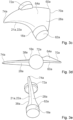
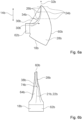
- FIGS. 5 and 6a to 6e show a schematic representation of a part of a further turbine device 10b.
- the additional turbine device 10b has an additional impeller blade unit 16b with additional impeller blades, of which only one additional impeller blade 18b is described below.
- the further impeller vane unit 16b is free of vane rings.
- the other impeller blade 18b is free of guide elements.
- the further impeller blade 18b is immovably connected to a further impeller blade hub 58b.
Landscapes
- Engineering & Computer Science (AREA)
- General Engineering & Computer Science (AREA)
- Mechanical Engineering (AREA)
- Civil Engineering (AREA)
- Structural Engineering (AREA)
- Chemical & Material Sciences (AREA)
- Combustion & Propulsion (AREA)
- Hydraulic Turbines (AREA)
- Structures Of Non-Positive Displacement Pumps (AREA)
- Other Liquid Machine Or Engine Such As Wave Power Use (AREA)
Applications Claiming Priority (2)
| Application Number | Priority Date | Filing Date | Title |
|---|---|---|---|
| DE102019113848.5A DE102019113848A1 (de) | 2019-05-23 | 2019-05-23 | Turbinenvorrichtung |
| PCT/EP2020/063938 WO2020234285A1 (de) | 2019-05-23 | 2020-05-19 | Turbinenvorrichtung |
Publications (2)
| Publication Number | Publication Date |
|---|---|
| EP3973176A1 EP3973176A1 (de) | 2022-03-30 |
| EP3973176B1 true EP3973176B1 (de) | 2023-07-26 |
Family
ID=71094262
Family Applications (1)
| Application Number | Title | Priority Date | Filing Date |
|---|---|---|---|
| EP20732734.7A Active EP3973176B1 (de) | 2019-05-23 | 2020-05-19 | Turbinenvorrichtung |
Country Status (7)
| Country | Link |
|---|---|
| EP (1) | EP3973176B1 (da) |
| CA (1) | CA3141514C (da) |
| DE (1) | DE102019113848A1 (da) |
| DK (1) | DK3973176T3 (da) |
| FI (1) | FI3973176T3 (da) |
| HU (1) | HUE063780T2 (da) |
| WO (1) | WO2020234285A1 (da) |
Cited By (1)
| Publication number | Priority date | Publication date | Assignee | Title |
|---|---|---|---|---|
| WO2025201753A1 (en) | 2024-03-25 | 2025-10-02 | Voith Patent Gmbh | Axial turbine with adjustable pitch blades |
Families Citing this family (1)
| Publication number | Priority date | Publication date | Assignee | Title |
|---|---|---|---|---|
| US20260002507A1 (en) * | 2023-09-01 | 2026-01-01 | Natel Energy Holdings, Inc. | Hydraulic turbine |
Family Cites Families (7)
| Publication number | Priority date | Publication date | Assignee | Title |
|---|---|---|---|---|
| US5947679A (en) * | 1996-03-28 | 1999-09-07 | Voith Hydro, Inc. | Adjustable blade turbines |
| US5997242A (en) * | 1996-12-02 | 1999-12-07 | Alden Research Laboratory, Inc. | Hydraulic turbine |
| NL2003467C2 (nl) | 2009-09-10 | 2011-03-14 | Nijhuis Pompen B V | Visvriendelijke pomp- of turbineinrichting. |
| NL2008948C2 (nl) * | 2012-06-06 | 2013-12-09 | G A M Manshanden Man B V | Scheepsschroef. |
| NL2012503C2 (nl) * | 2013-12-24 | 2015-06-26 | Flowserve B V | Waaier voor een pomp of turbine en pomp of turbine met waaier. |
| DE102014004506A1 (de) * | 2014-03-25 | 2016-01-21 | Christoph Oelsner | Fischökologische Wasserkraftanlage |
| CN105626573A (zh) * | 2015-12-24 | 2016-06-01 | 江苏大学 | 一种基于鱼存活率预测的鱼类友好型轴流泵的设计方法 |
-
2019
- 2019-05-23 DE DE102019113848.5A patent/DE102019113848A1/de not_active Withdrawn
-
2020
- 2020-05-19 HU HUE20732734A patent/HUE063780T2/hu unknown
- 2020-05-19 CA CA3141514A patent/CA3141514C/en active Active
- 2020-05-19 WO PCT/EP2020/063938 patent/WO2020234285A1/de not_active Ceased
- 2020-05-19 DK DK20732734.7T patent/DK3973176T3/da active
- 2020-05-19 EP EP20732734.7A patent/EP3973176B1/de active Active
- 2020-05-19 FI FIEP20732734.7T patent/FI3973176T3/fi active
Cited By (1)
| Publication number | Priority date | Publication date | Assignee | Title |
|---|---|---|---|---|
| WO2025201753A1 (en) | 2024-03-25 | 2025-10-02 | Voith Patent Gmbh | Axial turbine with adjustable pitch blades |
Also Published As
| Publication number | Publication date |
|---|---|
| DE102019113848A1 (de) | 2020-11-26 |
| FI3973176T3 (fi) | 2023-11-02 |
| DK3973176T3 (da) | 2023-10-30 |
| CA3141514A1 (en) | 2020-11-26 |
| CA3141514C (en) | 2025-06-10 |
| HUE063780T2 (hu) | 2024-01-28 |
| EP3973176A1 (de) | 2022-03-30 |
| WO2020234285A1 (de) | 2020-11-26 |
| BR112021023494A2 (pt) | 2022-01-18 |
Similar Documents
| Publication | Publication Date | Title |
|---|---|---|
| DE2852554C2 (de) | Rotor für eine Strömungsmaschine | |
| EP2025945B1 (de) | Strömungsarbeitsmaschine mit Ringkanalwandausnehmung | |
| EP1632662B1 (de) | Strömungsarbeitsmaschine mit Fluidentnahme | |
| EP3655664B1 (de) | Flügel für das laufrad eines ventilators, laufrad sowie axialventilator, diagonalventilator oder radialventilator | |
| EP3486499B1 (de) | Kühlerlüftermodul | |
| EP2627907B1 (de) | Seitenkanalgebläse, insbesondere sekundärluftgebläse für eine verbrennungskraftmaschine | |
| EP2096316B1 (de) | Gehäusestrukturierung für Axialverdichter im Nabenbereich | |
| DE2851406C3 (de) | Windturbine | |
| DE810500C (de) | Windturbine | |
| EP2003292A2 (de) | Schaufeldeckband mit Überstand | |
| EP2025946A2 (de) | Schaufeldeckband mit Sperrstrahlerzeugung | |
| WO1998044240A1 (de) | Oberflächenstruktur für die wand eines strömungskanals oder einer turbinenschaufel | |
| DE60128324T2 (de) | Gasturbinenschaufelform | |
| EP3880967B1 (de) | Diagonalventilator mit nachleiteinrichtung | |
| EP2594478A1 (de) | Propelleranordnung, insbesondere für Wasserfahrzeuge | |
| EP3973176B1 (de) | Turbinenvorrichtung | |
| EP1163425A1 (de) | Turbinenschaufel | |
| DE19722353A1 (de) | Kreiselpumpe mit einer Einlaufleiteinrichtung | |
| DE102004029107A1 (de) | Francis-Turbine | |
| DE69625917T2 (de) | Radiales lüfterrad | |
| EP3078804A1 (de) | Deckbandanordnung einer schaufelreihe von stator- oder rotorschaufeln und zugehörige turbine | |
| DE102016102732A1 (de) | Mixed-Flow-Turbinenrad eines Abgasturboladers sowie Abgasturbine mit einem solchen Turbinenrad | |
| EP2607625B1 (de) | Turbomaschine und turbomaschinenstufe | |
| DE102004029109A1 (de) | Francisturbine | |
| DE112017006146T5 (de) | Trennbaugruppe mit einer einteiligen impulsturbine |
Legal Events
| Date | Code | Title | Description |
|---|---|---|---|
| STAA | Information on the status of an ep patent application or granted ep patent |
Free format text: STATUS: UNKNOWN |
|
| STAA | Information on the status of an ep patent application or granted ep patent |
Free format text: STATUS: THE INTERNATIONAL PUBLICATION HAS BEEN MADE |
|
| PUAI | Public reference made under article 153(3) epc to a published international application that has entered the european phase |
Free format text: ORIGINAL CODE: 0009012 |
|
| STAA | Information on the status of an ep patent application or granted ep patent |
Free format text: STATUS: REQUEST FOR EXAMINATION WAS MADE |
|
| 17P | Request for examination filed |
Effective date: 20211214 |
|
| AK | Designated contracting states |
Kind code of ref document: A1 Designated state(s): AL AT BE BG CH CY CZ DE DK EE ES FI FR GB GR HR HU IE IS IT LI LT LU LV MC MK MT NL NO PL PT RO RS SE SI SK SM TR |
|
| DAV | Request for validation of the european patent (deleted) | ||
| DAX | Request for extension of the european patent (deleted) | ||
| REG | Reference to a national code |
Ref country code: DE Ref legal event code: R079 Free format text: PREVIOUS MAIN CLASS: F03B0003120000 Ipc: E02B0009060000 Ref document number: 502020004399 Country of ref document: DE |
|
| GRAP | Despatch of communication of intention to grant a patent |
Free format text: ORIGINAL CODE: EPIDOSNIGR1 |
|
| STAA | Information on the status of an ep patent application or granted ep patent |
Free format text: STATUS: GRANT OF PATENT IS INTENDED |
|
| RIC1 | Information provided on ipc code assigned before grant |
Ipc: F03B 3/12 20060101ALI20230127BHEP Ipc: E02B 9/06 20060101AFI20230127BHEP |
|
| INTG | Intention to grant announced |
Effective date: 20230214 |
|
| GRAS | Grant fee paid |
Free format text: ORIGINAL CODE: EPIDOSNIGR3 |
|
| GRAA | (expected) grant |
Free format text: ORIGINAL CODE: 0009210 |
|
| STAA | Information on the status of an ep patent application or granted ep patent |
Free format text: STATUS: THE PATENT HAS BEEN GRANTED |
|
| AK | Designated contracting states |
Kind code of ref document: B1 Designated state(s): AL AT BE BG CH CY CZ DE DK EE ES FI FR GB GR HR HU IE IS IT LI LT LU LV MC MK MT NL NO PL PT RO RS SE SI SK SM TR |
|
| REG | Reference to a national code |
Ref country code: CH Ref legal event code: EP |
|
| P01 | Opt-out of the competence of the unified patent court (upc) registered |
Effective date: 20230622 |
|
| REG | Reference to a national code |
Ref country code: IE Ref legal event code: FG4D Free format text: LANGUAGE OF EP DOCUMENT: GERMAN |
|
| REG | Reference to a national code |
Ref country code: DE Ref legal event code: R096 Ref document number: 502020004399 Country of ref document: DE |
|
| REG | Reference to a national code |
Ref country code: DK Ref legal event code: T3 Effective date: 20231027 |
|
| REG | Reference to a national code |
Ref country code: FI Ref legal event code: FGE |
|
| REG | Reference to a national code |
Ref country code: LT Ref legal event code: MG9D |
|
| REG | Reference to a national code |
Ref country code: SE Ref legal event code: TRGR |
|
| REG | Reference to a national code |
Ref country code: NL Ref legal event code: FP |
|
| PG25 | Lapsed in a contracting state [announced via postgrant information from national office to epo] |
Ref country code: GR Free format text: LAPSE BECAUSE OF FAILURE TO SUBMIT A TRANSLATION OF THE DESCRIPTION OR TO PAY THE FEE WITHIN THE PRESCRIBED TIME-LIMIT Effective date: 20231027 |
|
| PG25 | Lapsed in a contracting state [announced via postgrant information from national office to epo] |
Ref country code: IS Free format text: LAPSE BECAUSE OF FAILURE TO SUBMIT A TRANSLATION OF THE DESCRIPTION OR TO PAY THE FEE WITHIN THE PRESCRIBED TIME-LIMIT Effective date: 20231126 |
|
| REG | Reference to a national code |
Ref country code: HU Ref legal event code: AG4A Ref document number: E063780 Country of ref document: HU |
|
| PG25 | Lapsed in a contracting state [announced via postgrant information from national office to epo] |
Ref country code: RS Free format text: LAPSE BECAUSE OF FAILURE TO SUBMIT A TRANSLATION OF THE DESCRIPTION OR TO PAY THE FEE WITHIN THE PRESCRIBED TIME-LIMIT Effective date: 20230726 Ref country code: PT Free format text: LAPSE BECAUSE OF FAILURE TO SUBMIT A TRANSLATION OF THE DESCRIPTION OR TO PAY THE FEE WITHIN THE PRESCRIBED TIME-LIMIT Effective date: 20231127 Ref country code: NO Free format text: LAPSE BECAUSE OF FAILURE TO SUBMIT A TRANSLATION OF THE DESCRIPTION OR TO PAY THE FEE WITHIN THE PRESCRIBED TIME-LIMIT Effective date: 20231026 Ref country code: LV Free format text: LAPSE BECAUSE OF FAILURE TO SUBMIT A TRANSLATION OF THE DESCRIPTION OR TO PAY THE FEE WITHIN THE PRESCRIBED TIME-LIMIT Effective date: 20230726 Ref country code: LT Free format text: LAPSE BECAUSE OF FAILURE TO SUBMIT A TRANSLATION OF THE DESCRIPTION OR TO PAY THE FEE WITHIN THE PRESCRIBED TIME-LIMIT Effective date: 20230726 Ref country code: IS Free format text: LAPSE BECAUSE OF FAILURE TO SUBMIT A TRANSLATION OF THE DESCRIPTION OR TO PAY THE FEE WITHIN THE PRESCRIBED TIME-LIMIT Effective date: 20231126 Ref country code: HR Free format text: LAPSE BECAUSE OF FAILURE TO SUBMIT A TRANSLATION OF THE DESCRIPTION OR TO PAY THE FEE WITHIN THE PRESCRIBED TIME-LIMIT Effective date: 20230726 Ref country code: GR Free format text: LAPSE BECAUSE OF FAILURE TO SUBMIT A TRANSLATION OF THE DESCRIPTION OR TO PAY THE FEE WITHIN THE PRESCRIBED TIME-LIMIT Effective date: 20231027 |
|
| PG25 | Lapsed in a contracting state [announced via postgrant information from national office to epo] |
Ref country code: PL Free format text: LAPSE BECAUSE OF FAILURE TO SUBMIT A TRANSLATION OF THE DESCRIPTION OR TO PAY THE FEE WITHIN THE PRESCRIBED TIME-LIMIT Effective date: 20230726 |
|
| PG25 | Lapsed in a contracting state [announced via postgrant information from national office to epo] |
Ref country code: ES Free format text: LAPSE BECAUSE OF FAILURE TO SUBMIT A TRANSLATION OF THE DESCRIPTION OR TO PAY THE FEE WITHIN THE PRESCRIBED TIME-LIMIT Effective date: 20230726 |
|
| REG | Reference to a national code |
Ref country code: DE Ref legal event code: R097 Ref document number: 502020004399 Country of ref document: DE |
|
| PG25 | Lapsed in a contracting state [announced via postgrant information from national office to epo] |
Ref country code: SM Free format text: LAPSE BECAUSE OF FAILURE TO SUBMIT A TRANSLATION OF THE DESCRIPTION OR TO PAY THE FEE WITHIN THE PRESCRIBED TIME-LIMIT Effective date: 20230726 Ref country code: RO Free format text: LAPSE BECAUSE OF FAILURE TO SUBMIT A TRANSLATION OF THE DESCRIPTION OR TO PAY THE FEE WITHIN THE PRESCRIBED TIME-LIMIT Effective date: 20230726 Ref country code: ES Free format text: LAPSE BECAUSE OF FAILURE TO SUBMIT A TRANSLATION OF THE DESCRIPTION OR TO PAY THE FEE WITHIN THE PRESCRIBED TIME-LIMIT Effective date: 20230726 Ref country code: EE Free format text: LAPSE BECAUSE OF FAILURE TO SUBMIT A TRANSLATION OF THE DESCRIPTION OR TO PAY THE FEE WITHIN THE PRESCRIBED TIME-LIMIT Effective date: 20230726 Ref country code: CZ Free format text: LAPSE BECAUSE OF FAILURE TO SUBMIT A TRANSLATION OF THE DESCRIPTION OR TO PAY THE FEE WITHIN THE PRESCRIBED TIME-LIMIT Effective date: 20230726 Ref country code: SK Free format text: LAPSE BECAUSE OF FAILURE TO SUBMIT A TRANSLATION OF THE DESCRIPTION OR TO PAY THE FEE WITHIN THE PRESCRIBED TIME-LIMIT Effective date: 20230726 |
|
| PLBE | No opposition filed within time limit |
Free format text: ORIGINAL CODE: 0009261 |
|
| STAA | Information on the status of an ep patent application or granted ep patent |
Free format text: STATUS: NO OPPOSITION FILED WITHIN TIME LIMIT |
|
| 26N | No opposition filed |
Effective date: 20240429 |
|
| PG25 | Lapsed in a contracting state [announced via postgrant information from national office to epo] |
Ref country code: SI Free format text: LAPSE BECAUSE OF FAILURE TO SUBMIT A TRANSLATION OF THE DESCRIPTION OR TO PAY THE FEE WITHIN THE PRESCRIBED TIME-LIMIT Effective date: 20230726 |
|
| PG25 | Lapsed in a contracting state [announced via postgrant information from national office to epo] |
Ref country code: BG Free format text: LAPSE BECAUSE OF FAILURE TO SUBMIT A TRANSLATION OF THE DESCRIPTION OR TO PAY THE FEE WITHIN THE PRESCRIBED TIME-LIMIT Effective date: 20230726 |
|
| PG25 | Lapsed in a contracting state [announced via postgrant information from national office to epo] |
Ref country code: BG Free format text: LAPSE BECAUSE OF FAILURE TO SUBMIT A TRANSLATION OF THE DESCRIPTION OR TO PAY THE FEE WITHIN THE PRESCRIBED TIME-LIMIT Effective date: 20230726 |
|
| PG25 | Lapsed in a contracting state [announced via postgrant information from national office to epo] |
Ref country code: MC Free format text: LAPSE BECAUSE OF FAILURE TO SUBMIT A TRANSLATION OF THE DESCRIPTION OR TO PAY THE FEE WITHIN THE PRESCRIBED TIME-LIMIT Effective date: 20230726 |
|
| PG25 | Lapsed in a contracting state [announced via postgrant information from national office to epo] |
Ref country code: LU Free format text: LAPSE BECAUSE OF NON-PAYMENT OF DUE FEES Effective date: 20240519 |
|
| PG25 | Lapsed in a contracting state [announced via postgrant information from national office to epo] |
Ref country code: MC Free format text: LAPSE BECAUSE OF FAILURE TO SUBMIT A TRANSLATION OF THE DESCRIPTION OR TO PAY THE FEE WITHIN THE PRESCRIBED TIME-LIMIT Effective date: 20230726 Ref country code: LU Free format text: LAPSE BECAUSE OF NON-PAYMENT OF DUE FEES Effective date: 20240519 |
|
| PG25 | Lapsed in a contracting state [announced via postgrant information from national office to epo] |
Ref country code: IE Free format text: LAPSE BECAUSE OF NON-PAYMENT OF DUE FEES Effective date: 20240519 |
|
| PGFP | Annual fee paid to national office [announced via postgrant information from national office to epo] |
Ref country code: NL Payment date: 20250522 Year of fee payment: 6 |
|
| PGFP | Annual fee paid to national office [announced via postgrant information from national office to epo] |
Ref country code: FI Payment date: 20250520 Year of fee payment: 6 |
|
| PGFP | Annual fee paid to national office [announced via postgrant information from national office to epo] |
Ref country code: DE Payment date: 20250519 Year of fee payment: 6 |
|
| PGFP | Annual fee paid to national office [announced via postgrant information from national office to epo] |
Ref country code: GB Payment date: 20250522 Year of fee payment: 6 Ref country code: DK Payment date: 20250521 Year of fee payment: 6 |
|
| PGFP | Annual fee paid to national office [announced via postgrant information from national office to epo] |
Ref country code: BE Payment date: 20250520 Year of fee payment: 6 Ref country code: IT Payment date: 20250530 Year of fee payment: 6 |
|
| PGFP | Annual fee paid to national office [announced via postgrant information from national office to epo] |
Ref country code: HU Payment date: 20250514 Year of fee payment: 6 Ref country code: FR Payment date: 20250526 Year of fee payment: 6 |
|
| PGFP | Annual fee paid to national office [announced via postgrant information from national office to epo] |
Ref country code: CH Payment date: 20250601 Year of fee payment: 6 |
|
| PGFP | Annual fee paid to national office [announced via postgrant information from national office to epo] |
Ref country code: AT Payment date: 20250721 Year of fee payment: 5 |
|
| PGFP | Annual fee paid to national office [announced via postgrant information from national office to epo] |
Ref country code: SE Payment date: 20250522 Year of fee payment: 6 |
|
| PG25 | Lapsed in a contracting state [announced via postgrant information from national office to epo] |
Ref country code: CY Free format text: LAPSE BECAUSE OF FAILURE TO SUBMIT A TRANSLATION OF THE DESCRIPTION OR TO PAY THE FEE WITHIN THE PRESCRIBED TIME-LIMIT; INVALID AB INITIO Effective date: 20200519 |
|
| REG | Reference to a national code |
Ref country code: DE Ref legal event code: R082 Ref document number: 502020004399 Country of ref document: DE Representative=s name: DAUB PARTG MBB, DE |