EP3973604B1 - Geschirmte sammelschiene - Google Patents
Geschirmte sammelschiene Download PDFInfo
- Publication number
- EP3973604B1 EP3973604B1 EP20724197.7A EP20724197A EP3973604B1 EP 3973604 B1 EP3973604 B1 EP 3973604B1 EP 20724197 A EP20724197 A EP 20724197A EP 3973604 B1 EP3973604 B1 EP 3973604B1
- Authority
- EP
- European Patent Office
- Prior art keywords
- busbar
- shielding
- conductor bars
- conductor
- sides
- Prior art date
- Legal status (The legal status is an assumption and is not a legal conclusion. Google has not performed a legal analysis and makes no representation as to the accuracy of the status listed.)
- Active
Links
Images


Classifications
-
- H—ELECTRICITY
- H02—GENERATION; CONVERSION OR DISTRIBUTION OF ELECTRIC POWER
- H02G—INSTALLATION OF ELECTRIC CABLES OR LINES, OR OF COMBINED OPTICAL AND ELECTRIC CABLES OR LINES
- H02G5/00—Installations of bus-bars
- H02G5/06—Totally-enclosed installations, e.g. in metal casings
-
- H—ELECTRICITY
- H02—GENERATION; CONVERSION OR DISTRIBUTION OF ELECTRIC POWER
- H02G—INSTALLATION OF ELECTRIC CABLES OR LINES, OR OF COMBINED OPTICAL AND ELECTRIC CABLES OR LINES
- H02G5/00—Installations of bus-bars
- H02G5/002—Joints between bus-bars for compensating thermal expansion
-
- H—ELECTRICITY
- H02—GENERATION; CONVERSION OR DISTRIBUTION OF ELECTRIC POWER
- H02G—INSTALLATION OF ELECTRIC CABLES OR LINES, OR OF COMBINED OPTICAL AND ELECTRIC CABLES OR LINES
- H02G5/00—Installations of bus-bars
- H02G5/005—Laminated bus-bars
Definitions
- the present invention regards systems for the transportation and distribution of electrical energy and more particularly it regards busbars.
- the busbars are prefabricated electric bars consisting of modular structures comprising conductor elements, normally in the form of rigid bars made of conductive material, typically copper or aluminium, in a support casing made of conductive or ferromagnetic or combined material, which also serves the function of thermal dissipation of the heat produced due to the Joule effect by such conductor bars and sometimes even a first containment of the emitted magnetic field.
- Busbars are used as an alternative to the use of electric cables, especially in the commercial and industrial field.
- the busbars can be used for conducting currents of a few tens up to several thousands of amperes, offering some advantages with respect to conventional cables such as, for example, modularity, ease of installation, safety and modularity of the components attached thereto such as shunts, sockets etc.
- busbars with respect to the electric cables lies in the fact that the electromagnetic compatibility, for example, a compact type of busbar traversed by a current intensity of about 2000 (A) (Amperes), is capable of guaranteeing a magnetic induction level lower than 3 ( ⁇ T) (Microteslas) within 1 m from the bar, limit established for the protection of people in Italy.
- ⁇ T magnetic induction level
- ⁇ T magnetic induction level
- ⁇ T magnetic induction level lower than 3
- ⁇ T magnetic induction level
- ⁇ T magnetic induction level lower than 3
- ⁇ T magnetic induction level lower than ⁇ T
- a conventional solution for mitigating the magnetic fields generated by the busbars provides for a shielding arranged on the external and wound on the casing, with the problem of entailing an increase in temperatures, especially in the case of the busbars traversed by currents with intensity higher than 400-500 (A).
- This solution also requires a complex work of adapting said outer shielding to the outer casing of the busbars, sometimes carried out by specialised technicians after installation in the place of use.
- Japanese patent application JP 09182260 discloses a busbar provided with a magnetic shielding which can consist of two juxtaposed and spaced U-shaped elements made of conductive material, for example copper or iron, arranged between the conductor bars and the outer casing. This solution is poorly effective at mitigating the magnetic fields outside the busbar due to the conductive material, which is poorly effective for this application, and the shape of such proposed shielding.
- Chinese utility model CN 202817654U describes a busbar provided with a monolithic tubular steel body inside the casing for reducing electromagnetic interference. This tubular body is difficult to manufacture and it complicates the assembling of the conductive bars therein.
- EP1652280 A1 describes an electrical power transmission line in which the electric cables are shielded by a shielding element made of ferromagnetic material and comprising a U-shaped base and a cover having an edge partially overlapping the base.
- US7786382 B2 shows a busbar arrangement wherein the neutral conductor acts as electromagnetic shielding.
- JPS515695 U describes another shielded busbar arrangement comprising U-shaped electromagnetic shielding elements.
- the object of the present invention is to overcome the drawbacks mentioned above by providing a shielding for busbars having an improved magnetic shielding effectiveness, that are easy to manufacture and quick to assemble.
- the primary characteristic of the busbar according to the present invention lies in the fact that the magnetic shielding structure, arranged between the conductor bars and the outer casing, consists of a first shielding element and a second shielding element, each of which is formed by at least one U-shaped folded strip comprising two fins and a base, made of ferromagnetic material and enclosing - on opposite sides - the conductor bars so that each fin of a shielding element is totally superimposed on the homologous fin of the other shielding element.
- the ferromagnetic material of the shielding elements allows the reduction of the magnetic induction by absorbing the magnetic field produced by the conductor bars: in particular, the pair of ferromagnetic shielding elements constitutes a magnetic circuit in which the reluctance of the air gap is minimised by increasing the facing surface, hence the superimposition of the fins of the screening elements further increases the effectiveness of the shielding structure.
- the shielding elements consist of anisotropic ferromagnetic strips. Thanks to this characteristic, the efficiency of the magnetic shielding of a busbar according to the invention can be improved since an anisotropic ferromagnetic material has a greater shielding capacity of a magnetic field than an isotropic material due to the known phenomenon of magnetic anisotropy, i.e. the directional dependence of the magnetic properties of a material.
- the anisotropic ferromagnetic strips have grains oriented in a direction orthogonal to the longitudinal axis of the conductor bars.
- each fin of the first shielding element is totally superimposed on the homologous fin of the second shielding element.
- At least one of the conductor bars is partially enclosed by a coating made of insulating material or the conductor bars are separated by insulating material.
- the plurality of conductor bars has a generally prismatic shape with two larger sides and two smaller sides.
- the bases of each shielding element face the respective surfaces of the smaller sides of the plurality of conductor bars and the fins face the respective surfaces of the larger sides of the plurality of conductor bars.
- the bases of each shielding element face the respective surfaces of the larger sides of the plurality of conductor bars and the fins face the respective surfaces of the smaller sides of the plurality of conductor bars.
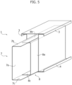
- a busbar comprising an outer support casing 2 in the form of an elongated parallelepiped and provided, at the smaller lateral faces thereof, with an upper flange 3 and a lower flange 4 is indicated with 1.
- a plurality of conductor bars 5 Arranged inside the casing 2 is a plurality of conductor bars 5 with a flattened rectangular-shaped cross-section, arranged parallel to each other along the longitudinal direction of the casing 2 so that the larger lateral surfaces of the adjacent conductor bars face each other.
- conductor bars 5 Provided for in the example illustrated in the figures are four conductor bars 5 according to a typical arrangement of the three-phase conductors (three phase conductors and one neutral conductor). It is clear that the number of conductor bars may vary depending on the applications.
- each conductor bar 5 is at contact with a coating made of insulating material 6.
- the busbar 1 comprises a shielding structure including a first and a second shielding element 7, 8, each of which is formed by a strip made of U-shaped folded ferromagnetic material.
- the first shielding element has a base 7a and two fins 7b, 7c which extend orthogonally to the base 7a on opposite sides thereof.
- the second shielding element 8 has a base 8a and two fins 8b, 8c which extend orthogonally to the base 8a on opposite sides thereof.
- the first shielding element 7 is arranged so that the fins 7b, 7c face the outer larger lateral surfaces of the respective conductor bars 5 and the base 7a faces the lower smaller surfaces of the group of conductor bars 5.
- the second shielding element 8 is arranged in a mirror-like manner with respect to the first shielding element 7, so that fin 8b is superimposed on fin 7b, fin 8c is superimposed on fin 7c and the base 8a faces the upper smaller surfaces of the group of conductor bars 5.
- the first shielding element 7 is shaped and arranged so that the fins 7b, 7c face the smaller lateral surfaces of the respective conductor bars (not represented in the figure so as to facilitate the viewing of the other elements) and the base 7a faces the larger surfaces of the group of conductor bars 5.
- the second shielding element 8 is arranged in a mirror-like manner with respect to the first shielding element 7, so that fin 8b is superimposed on fin 7b, fin 8c is superimposed on fin 7c and the base 8a faces the larger surfaces of the group of conductor bars 5.
- the shielding structure according to the invention can be assembled quickly and efficiently by simply applying the first shielding element 7 to the group of conductor bars 5 and then applying the second shielding element 8 in a mirror-like fashion to the first, so as to obtain a double shielding wall formed by superimposing the fins 7b, 8b, and 7c, 8c of each shielding element 7, 8 along the larger lateral surfaces of the conductor bars 5.
- the assembly of the busbar 1 is completed by inserting the group consisting of the conductor bars 5 and the shielding elements 7, 8 in the outer casing 2.
- the shielding elements 7, 8 are made of anisotropic ferromagnetic material with grains oriented in the direction represented by the arrows, i.e. orthogonal to the longitudinal axis of the busbar 1. This arrangement allows to further improve the efficiency of magnetic shielding.
- busbar 1 could be different from the one shown in the drawings, and it could have different shapes and dimensions.
Landscapes
- Shielding Devices Or Components To Electric Or Magnetic Fields (AREA)
- Installation Of Bus-Bars (AREA)
Claims (8)
- Sammelschiene (1), umfassend:mindestens einen starren Leiterstab (5),ein äußeres Tragegehäuse (2), das den mindestens einen Leiterstab (5) umschließt,eine zwischen dem mindestens einen Leiterstab (5) und dem Außengehäuse (2) angeordnete magnetische Abschirmstruktur, wobei diese magnetische Abschirmstruktur ein erstes Abschirmelement (7) und ein zweites Abschirmelement (8) umfasst, von denen jedes aus mindestens einem U-förmig gefalteten Streifen besteht, der zwei Finnen (7b, 7c, 8b, 8c) und einen Grundkörper (7a, 8a) umfasst, wobeidie Abschirmelemente (7, 8) aus ferromagnetischem Material bestehen und - auf gegenüberliegenden Seiten - den mindestens einen Leiterstab (5) umschließen, dadurch gekennzeichnet, dass jede Finne (7b, 7c) des ersten Abschirmelements (7) vollständig mit der homologen Finne (8b, 8c) des zweiten Abschirmelements (8) überlagert ist.
- Sammelschiene (1) nach Anspruch 1, dadurch gekennzeichnet, dass die Abschirmelemente (7, 8) aus anisotropen ferromagnetischen Streifen bestehen.
- Sammelschiene (1) nach Anspruch 2, dadurch gekennzeichnet, dass die anisotropen ferromagnetischen Streifen Körner aufweisen, die in einer Richtung orientiert sind, die rechtwinklig zur Längsachse des mindestens einen Leiterstabes (5) verläuft.
- Sammelschiene (1) nach einem der vorhergehenden Ansprüche, dadurch gekennzeichnet, dass sie eine Vielzahl von Leiterstäben (5) mit einem abgeflachten rechteckigen Querschnitt umfasst, die parallel zueinander in Längsrichtung angeordnet sind.
- Sammelschiene (1) nach Anspruch 4, dadurch gekennzeichnet, dass die Vielzahl von Leiterstäben (5) eine allgemein prismatische Form mit zwei größeren Seiten und zwei kleineren Seiten aufweist und die Grundkörper (7a, 8a) der Abschirmelemente (7, 8) den jeweiligen kleineren Seiten der Vielzahl von Leiterstäben (5) zugewandt sind und die Finnen (7b, 7c, 8b, 8c) den jeweiligen größeren Seiten der Vielzahl von Leiterstäben (5) zugewandt sind.
- Sammelschiene (1) nach Anspruch 4, dadurch gekennzeichnet, dass die Vielzahl von Leiterstäben (5) eine allgemein prismatische Form mit zwei größeren Seiten und zwei kleineren Seiten aufweist und die Grundkörper (7a, 8a) der Abschirmelemente (7, 8) den jeweiligen kleineren Seiten der Vielzahl von Leiterstäben (5) zugewandt sind und die Finnen (7b, 7c, 8b, 8c) den jeweiligen kleineren Seiten der Vielzahl von Leiterstäben (5) zugewandt sind.
- Sammelschiene (1) nach einem der Ansprüche 4 bis 6, dadurch gekennzeichnet, dass die Leiterstäbe (5) der Vielzahl durch Isoliermaterial (6) voneinander getrennt sind.
- Sammelschiene (1) nach einem der vorhergehenden Ansprüche, dadurch gekennzeichnet, dass das äußere Tragegehäuse (2), das den mindestens einen Leiterstab (5) umschließt, mit Flanschen (3, 4) versehen ist.
Priority Applications (1)
| Application Number | Priority Date | Filing Date | Title |
|---|---|---|---|
| HRP20250336TT HRP20250336T1 (hr) | 2019-05-20 | 2020-04-17 | Oklopljena sabirnica |
Applications Claiming Priority (2)
| Application Number | Priority Date | Filing Date | Title |
|---|---|---|---|
| IT201900001551 | 2019-05-20 | ||
| PCT/IB2020/053651 WO2020234660A1 (en) | 2019-05-20 | 2020-04-17 | Shielded busbar |
Publications (3)
| Publication Number | Publication Date |
|---|---|
| EP3973604A1 EP3973604A1 (de) | 2022-03-30 |
| EP3973604C0 EP3973604C0 (de) | 2024-12-25 |
| EP3973604B1 true EP3973604B1 (de) | 2024-12-25 |
Family
ID=70554124
Family Applications (1)
| Application Number | Title | Priority Date | Filing Date |
|---|---|---|---|
| EP20724197.7A Active EP3973604B1 (de) | 2019-05-20 | 2020-04-17 | Geschirmte sammelschiene |
Country Status (5)
| Country | Link |
|---|---|
| US (1) | US11451037B2 (de) |
| EP (1) | EP3973604B1 (de) |
| ES (1) | ES3015441T3 (de) |
| HR (1) | HRP20250336T1 (de) |
| WO (1) | WO2020234660A1 (de) |
Families Citing this family (1)
| Publication number | Priority date | Publication date | Assignee | Title |
|---|---|---|---|---|
| IT202300002754A1 (it) * | 2023-02-17 | 2024-08-17 | Eae Elektrik Asansor Endustri Insaat Sanayi Ve Ticaret Anonim Sir | Busbar schermato |
Citations (1)
| Publication number | Priority date | Publication date | Assignee | Title |
|---|---|---|---|---|
| JPS515695U (de) * | 1974-06-29 | 1976-01-16 |
Family Cites Families (4)
| Publication number | Priority date | Publication date | Assignee | Title |
|---|---|---|---|---|
| JPH09182260A (ja) * | 1995-12-26 | 1997-07-11 | Furukawa Electric Co Ltd:The | バスダクト |
| EP1652280B1 (de) * | 2003-07-30 | 2019-02-27 | Prysmian S.p.A. | Verfahren zum abschirmen des durch eine elektrische energieübertragungsleitung erzeugten magnetfeldes sowie derart abgeschirmte elektrische energieübertragungsleitung |
| US7786382B2 (en) * | 2008-01-10 | 2010-08-31 | Elio Burguera | High efficiency paired phases busway system |
| TWM429125U (en) * | 2011-09-30 | 2012-05-11 | Unelectra Internat Corp | Bus device capable of reducing electromagnetic interference |
-
2020
- 2020-04-17 WO PCT/IB2020/053651 patent/WO2020234660A1/en not_active Ceased
- 2020-04-17 ES ES20724197T patent/ES3015441T3/es active Active
- 2020-04-17 HR HRP20250336TT patent/HRP20250336T1/hr unknown
- 2020-04-17 US US17/291,130 patent/US11451037B2/en active Active
- 2020-04-17 EP EP20724197.7A patent/EP3973604B1/de active Active
Patent Citations (1)
| Publication number | Priority date | Publication date | Assignee | Title |
|---|---|---|---|---|
| JPS515695U (de) * | 1974-06-29 | 1976-01-16 |
Also Published As
| Publication number | Publication date |
|---|---|
| US20210391699A1 (en) | 2021-12-16 |
| US11451037B2 (en) | 2022-09-20 |
| EP3973604A1 (de) | 2022-03-30 |
| EP3973604C0 (de) | 2024-12-25 |
| HRP20250336T1 (hr) | 2025-05-09 |
| WO2020234660A1 (en) | 2020-11-26 |
| ES3015441T3 (en) | 2025-05-05 |
Similar Documents
| Publication | Publication Date | Title |
|---|---|---|
| JP4482477B2 (ja) | 複合型リアクトルの巻線構造 | |
| US8427271B2 (en) | Reactor part | |
| EP0977214B1 (de) | Transformatorkern aus amorphem Metall | |
| US20230215613A1 (en) | Thermal management of electromagnetic device | |
| US4886468A (en) | Insulated electrical power distribution busway tabs | |
| US10699836B2 (en) | Inductor and associated production method | |
| US4902998A (en) | Inductor assembly with cooled winding turns | |
| US3142809A (en) | Cooling arrangement for electrical apparatus having at least one multilayer winding | |
| JP7122505B2 (ja) | コイル及びそれを用いたモータ | |
| EP3973604B1 (de) | Geschirmte sammelschiene | |
| EP1100179A1 (de) | Wicklung für Motor oder Generator | |
| US8471661B2 (en) | Method for manufacturing coil, and a coil | |
| US10340071B2 (en) | Magnetic circuit for carrying at least one coil | |
| EP4418480A1 (de) | Abgeschirmte sammelschiene | |
| EP3282456B1 (de) | Traktionstransformator | |
| RU2781268C1 (ru) | Экранированный шинопровод | |
| CN118889720A (zh) | 一种定子冲片、定子、电机及车辆 | |
| US3362000A (en) | Means for increasing the inductance of shunt reactors | |
| KR100878615B1 (ko) | 전력 케이블 장치 및 그의 제조방법 | |
| KR100388604B1 (ko) | 타원형 타권 핼리시스로 권선된 평각 코일을 갖는 리액터 및 이의 제조 방법 | |
| WO2022221996A1 (en) | Bus-duct and associated manufacturing method | |
| CN223666106U (zh) | 电机及压缩机 | |
| EP1085632A1 (de) | Leiterstruktur zur Übertragung elektrischer Energie | |
| EP4394805A1 (de) | Transponierter elektrischer leiter und buchse | |
| CN119813577A (zh) | 电机及压缩机 |
Legal Events
| Date | Code | Title | Description |
|---|---|---|---|
| REG | Reference to a national code |
Ref country code: HR Ref legal event code: TUEP Ref document number: P20250336T Country of ref document: HR |
|
| STAA | Information on the status of an ep patent application or granted ep patent |
Free format text: STATUS: UNKNOWN |
|
| STAA | Information on the status of an ep patent application or granted ep patent |
Free format text: STATUS: THE INTERNATIONAL PUBLICATION HAS BEEN MADE |
|
| PUAI | Public reference made under article 153(3) epc to a published international application that has entered the european phase |
Free format text: ORIGINAL CODE: 0009012 |
|
| STAA | Information on the status of an ep patent application or granted ep patent |
Free format text: STATUS: REQUEST FOR EXAMINATION WAS MADE |
|
| 17P | Request for examination filed |
Effective date: 20210420 |
|
| AK | Designated contracting states |
Kind code of ref document: A1 Designated state(s): AL AT BE BG CH CY CZ DE DK EE ES FI FR GB GR HR HU IE IS IT LI LT LU LV MC MK MT NL NO PL PT RO RS SE SI SK SM TR |
|
| RAV | Requested validation state of the european patent: fee paid |
Extension state: TN Effective date: 20210420 Extension state: MA Effective date: 20210420 |
|
| RAX | Requested extension states of the european patent have changed |
Extension state: ME Payment date: 20210420 |
|
| GRAP | Despatch of communication of intention to grant a patent |
Free format text: ORIGINAL CODE: EPIDOSNIGR1 |
|
| STAA | Information on the status of an ep patent application or granted ep patent |
Free format text: STATUS: GRANT OF PATENT IS INTENDED |
|
| INTG | Intention to grant announced |
Effective date: 20240722 |
|
| GRAS | Grant fee paid |
Free format text: ORIGINAL CODE: EPIDOSNIGR3 |
|
| GRAA | (expected) grant |
Free format text: ORIGINAL CODE: 0009210 |
|
| STAA | Information on the status of an ep patent application or granted ep patent |
Free format text: STATUS: THE PATENT HAS BEEN GRANTED |
|
| AK | Designated contracting states |
Kind code of ref document: B1 Designated state(s): AL AT BE BG CH CY CZ DE DK EE ES FI FR GB GR HR HU IE IS IT LI LT LU LV MC MK MT NL NO PL PT RO RS SE SI SK SM TR |
|
| REG | Reference to a national code |
Ref country code: GB Ref legal event code: FG4D |
|
| REG | Reference to a national code |
Ref country code: CH Ref legal event code: EP |
|
| REG | Reference to a national code |
Ref country code: IE Ref legal event code: FG4D |
|
| REG | Reference to a national code |
Ref country code: DE Ref legal event code: R096 Ref document number: 602020043648 Country of ref document: DE |
|
| U01 | Request for unitary effect filed |
Effective date: 20250122 |
|
| U07 | Unitary effect registered |
Designated state(s): AT BE BG DE DK EE FI FR IT LT LU LV MT NL PT RO SE SI Effective date: 20250128 |
|
| RAP4 | Party data changed (patent owner data changed or rights of a patent transferred) |
Owner name: BESHIELDING S.R.L. |
|
| U1H | Name or address of the proprietor changed after the registration of the unitary effect |
Owner name: BESHIELDING S.R.L.; IT |
|
| U20 | Renewal fee for the european patent with unitary effect paid |
Year of fee payment: 6 Effective date: 20250206 |
|
| PG25 | Lapsed in a contracting state [announced via postgrant information from national office to epo] |
Ref country code: NO Free format text: LAPSE BECAUSE OF FAILURE TO SUBMIT A TRANSLATION OF THE DESCRIPTION OR TO PAY THE FEE WITHIN THE PRESCRIBED TIME-LIMIT Effective date: 20250325 |
|
| PG25 | Lapsed in a contracting state [announced via postgrant information from national office to epo] |
Ref country code: GR Free format text: LAPSE BECAUSE OF FAILURE TO SUBMIT A TRANSLATION OF THE DESCRIPTION OR TO PAY THE FEE WITHIN THE PRESCRIBED TIME-LIMIT Effective date: 20250326 |
|
| REG | Reference to a national code |
Ref country code: HR Ref legal event code: ODRP Ref document number: P20250336T Country of ref document: HR Payment date: 20250319 Year of fee payment: 6 |
|
| PG25 | Lapsed in a contracting state [announced via postgrant information from national office to epo] |
Ref country code: RS Free format text: LAPSE BECAUSE OF FAILURE TO SUBMIT A TRANSLATION OF THE DESCRIPTION OR TO PAY THE FEE WITHIN THE PRESCRIBED TIME-LIMIT Effective date: 20250325 |
|
| REG | Reference to a national code |
Ref country code: HR Ref legal event code: T1PR Ref document number: P20250336 Country of ref document: HR |
|
| PG25 | Lapsed in a contracting state [announced via postgrant information from national office to epo] |
Ref country code: SM Free format text: LAPSE BECAUSE OF FAILURE TO SUBMIT A TRANSLATION OF THE DESCRIPTION OR TO PAY THE FEE WITHIN THE PRESCRIBED TIME-LIMIT Effective date: 20241225 |
|
| PG25 | Lapsed in a contracting state [announced via postgrant information from national office to epo] |
Ref country code: PL Free format text: LAPSE BECAUSE OF FAILURE TO SUBMIT A TRANSLATION OF THE DESCRIPTION OR TO PAY THE FEE WITHIN THE PRESCRIBED TIME-LIMIT Effective date: 20241225 |
|
| PGFP | Annual fee paid to national office [announced via postgrant information from national office to epo] |
Ref country code: ES Payment date: 20250505 Year of fee payment: 6 |
|
| PG25 | Lapsed in a contracting state [announced via postgrant information from national office to epo] |
Ref country code: IS Free format text: LAPSE BECAUSE OF FAILURE TO SUBMIT A TRANSLATION OF THE DESCRIPTION OR TO PAY THE FEE WITHIN THE PRESCRIBED TIME-LIMIT Effective date: 20250425 |
|
| PGFP | Annual fee paid to national office [announced via postgrant information from national office to epo] |
Ref country code: HR Payment date: 20250417 Year of fee payment: 6 |
|
| PGFP | Annual fee paid to national office [announced via postgrant information from national office to epo] |
Ref country code: CH Payment date: 20250501 Year of fee payment: 6 |
|
| PG25 | Lapsed in a contracting state [announced via postgrant information from national office to epo] |
Ref country code: SK Free format text: LAPSE BECAUSE OF FAILURE TO SUBMIT A TRANSLATION OF THE DESCRIPTION OR TO PAY THE FEE WITHIN THE PRESCRIBED TIME-LIMIT Effective date: 20241225 |
|
| PG25 | Lapsed in a contracting state [announced via postgrant information from national office to epo] |
Ref country code: CZ Free format text: LAPSE BECAUSE OF FAILURE TO SUBMIT A TRANSLATION OF THE DESCRIPTION OR TO PAY THE FEE WITHIN THE PRESCRIBED TIME-LIMIT Effective date: 20241225 |
|
| PLBE | No opposition filed within time limit |
Free format text: ORIGINAL CODE: 0009261 |
|
| STAA | Information on the status of an ep patent application or granted ep patent |
Free format text: STATUS: NO OPPOSITION FILED WITHIN TIME LIMIT |
|
| 26N | No opposition filed |
Effective date: 20250926 |
|
| PG25 | Lapsed in a contracting state [announced via postgrant information from national office to epo] |
Ref country code: MC Free format text: LAPSE BECAUSE OF FAILURE TO SUBMIT A TRANSLATION OF THE DESCRIPTION OR TO PAY THE FEE WITHIN THE PRESCRIBED TIME-LIMIT Effective date: 20241225 |
|
| PGFP | Annual fee paid to national office [announced via postgrant information from national office to epo] |
Ref country code: GB Payment date: 20260309 Year of fee payment: 7 |
|
| PG25 | Lapsed in a contracting state [announced via postgrant information from national office to epo] |
Ref country code: IE Free format text: LAPSE BECAUSE OF NON-PAYMENT OF DUE FEES Effective date: 20250417 |
|
| VS25 | Lapsed in a validation state [announced via postgrant information from nat. office to epo] |
Ref country code: MA Free format text: LAPSE BECAUSE OF FAILURE TO SUBMIT A TRANSLATION OF THE DESCRIPTION OR TO PAY THE FEE WITHIN THE PRESCRIBED TIME-LIMIT; INVALID AB INITIO Effective date: 20200417 |
|
| PGFP | Annual fee paid to national office [announced via postgrant information from national office to epo] |
Ref country code: TR Payment date: 20260330 Year of fee payment: 7 |
|
| REG | Reference to a national code |
Ref country code: HR Ref legal event code: ODRP Ref document number: P20250336 Country of ref document: HR Payment date: 20260330 Year of fee payment: 7 |