EP3973817A1 - Stützvorrichtung für ein höhenverstellbares tischgestell - Google Patents
Stützvorrichtung für ein höhenverstellbares tischgestell Download PDFInfo
- Publication number
- EP3973817A1 EP3973817A1 EP21175115.1A EP21175115A EP3973817A1 EP 3973817 A1 EP3973817 A1 EP 3973817A1 EP 21175115 A EP21175115 A EP 21175115A EP 3973817 A1 EP3973817 A1 EP 3973817A1
- Authority
- EP
- European Patent Office
- Prior art keywords
- extension
- support
- component
- support element
- cable
- Prior art date
- Legal status (The legal status is an assumption and is not a legal conclusion. Google has not performed a legal analysis and makes no representation as to the accuracy of the status listed.)
- Granted
Links
Images


Classifications
-
- A—HUMAN NECESSITIES
- A47—FURNITURE; DOMESTIC ARTICLES OR APPLIANCES; COFFEE MILLS; SPICE MILLS; SUCTION CLEANERS IN GENERAL
- A47B—TABLES; DESKS; OFFICE FURNITURE; CABINETS; DRAWERS; GENERAL DETAILS OF FURNITURE
- A47B9/00—Tables with tops of variable height
- A47B9/10—Tables with tops of variable height with vertically-acting fluid cylinder
-
- A—HUMAN NECESSITIES
- A47—FURNITURE; DOMESTIC ARTICLES OR APPLIANCES; COFFEE MILLS; SPICE MILLS; SUCTION CLEANERS IN GENERAL
- A47B—TABLES; DESKS; OFFICE FURNITURE; CABINETS; DRAWERS; GENERAL DETAILS OF FURNITURE
- A47B9/00—Tables with tops of variable height
-
- A—HUMAN NECESSITIES
- A47—FURNITURE; DOMESTIC ARTICLES OR APPLIANCES; COFFEE MILLS; SPICE MILLS; SUCTION CLEANERS IN GENERAL
- A47B—TABLES; DESKS; OFFICE FURNITURE; CABINETS; DRAWERS; GENERAL DETAILS OF FURNITURE
- A47B13/00—Details of tables or desks
- A47B13/02—Underframes
-
- A—HUMAN NECESSITIES
- A47—FURNITURE; DOMESTIC ARTICLES OR APPLIANCES; COFFEE MILLS; SPICE MILLS; SUCTION CLEANERS IN GENERAL
- A47B—TABLES; DESKS; OFFICE FURNITURE; CABINETS; DRAWERS; GENERAL DETAILS OF FURNITURE
- A47B13/00—Details of tables or desks
- A47B13/08—Table tops; Rims therefor
-
- A—HUMAN NECESSITIES
- A47—FURNITURE; DOMESTIC ARTICLES OR APPLIANCES; COFFEE MILLS; SPICE MILLS; SUCTION CLEANERS IN GENERAL
- A47B—TABLES; DESKS; OFFICE FURNITURE; CABINETS; DRAWERS; GENERAL DETAILS OF FURNITURE
- A47B9/00—Tables with tops of variable height
- A47B9/02—Tables with tops of variable height with balancing device, e.g. by springs, by weight
-
- A—HUMAN NECESSITIES
- A47—FURNITURE; DOMESTIC ARTICLES OR APPLIANCES; COFFEE MILLS; SPICE MILLS; SUCTION CLEANERS IN GENERAL
- A47B—TABLES; DESKS; OFFICE FURNITURE; CABINETS; DRAWERS; GENERAL DETAILS OF FURNITURE
- A47B9/00—Tables with tops of variable height
- A47B9/12—Tables with tops of variable height with flexible height-adjusting means, e.g. rope, chain
-
- A—HUMAN NECESSITIES
- A47—FURNITURE; DOMESTIC ARTICLES OR APPLIANCES; COFFEE MILLS; SPICE MILLS; SUCTION CLEANERS IN GENERAL
- A47B—TABLES; DESKS; OFFICE FURNITURE; CABINETS; DRAWERS; GENERAL DETAILS OF FURNITURE
- A47B2200/00—General construction of tables or desks
- A47B2200/0035—Tables or desks with features relating to adjustability or folding
- A47B2200/005—Leg adjustment
-
- A—HUMAN NECESSITIES
- A47—FURNITURE; DOMESTIC ARTICLES OR APPLIANCES; COFFEE MILLS; SPICE MILLS; SUCTION CLEANERS IN GENERAL
- A47B—TABLES; DESKS; OFFICE FURNITURE; CABINETS; DRAWERS; GENERAL DETAILS OF FURNITURE
- A47B9/00—Tables with tops of variable height
- A47B9/20—Telescopic guides
Definitions
- the invention relates to a support device for a height-adjustable table, in particular for a height-adjustable table with a plurality of support elements.
- height-adjustable tables which have several height-adjustable table legs, which are also referred to below as support elements, in order to be able to carry and lift loads that are set up on a table top of the height-adjustable table safely and reliably.
- the problem here is that components of the height-adjustable table legs can tilt and thus jam if the table legs do not move synchronously.
- the invention is based on the object of eliminating the above problems and providing a support device for a height-adjustable table which enables the height-adjustable table to function reliably over an entire adjustment range for an ergonomic working height of the tabletop.
- a support device for a height-adjustable table has a first support element and at least one second support element, the first support element and the at least one second support element each having a first extension component, a second extension component and a third extension component.
- the first extension component, the second extension component and the third extension component are arranged such that they can be displaced relative to one another in order to bring about a change in length of the first support element and of the at least one second support element.
- the second design component is arranged in a direction of length change between the first design component and the third design component, and the first design component, the second design component and the third design component are coupled to one another such that, when the length change of the first support element and the at least one second support element , a displacement of the second design component to the first design component in a direction parallel to the change in length synchronously causes a displacement of the third design component to the second design component in the same direction.
- the support device also has a synchronization device which is designed to synchronize between the first support element and the at least one second support element, the displacement of the second outlay component relative to the first outlay component or the displacement of the third outlay component relative to the second outlay component.
- the defined movement of the individual extension components relative to one another makes it possible for bending moments applied to the support elements, which arise, for example, by resting on the edge of a table top during a height adjustment or by larger eccentric loads on the table top, to be absorbed without the need for guides or slides, which should allow the design components to move into one another with as little play as possible, are overly stressed.
- This defined movement is executed in a correspondingly synchronized manner, so that the multiple support elements cannot tilt.
- an extent of the displacement between the second outlay component and the first outlay component and an extent of the displacement between the third outlay component and the second outlay component are identical.
- the support device has an endless cable-type element and two third deflection rollers, which are arranged spaced apart in the direction of change in length of the first support element and the at least one second support element and are connected to the second extension component, the endless cable-like element is designed so that it is deflected without play by the two third deflection rollers and a section of the endless cable-like element in the direction of the change in length of the first support element and the at least one second support element between the two third deflection rollers with the first extension component and the third Outlay component is connected.
- the cable-type element is a steel strip.
- the design with a small diameter is possible, which also allows the use of deflection rollers with small dimensions, so that space is saved can be.
- a precisely defined movement of the individual design components relative to one another is possible.
- the third deflection rollers have a crowning on their running surface along their axis of rotation.
- the synchronization device has a first cable-type synchronization element, which is attached at one end to one of the extension components of the first support element and at the other end to the same extension component of the at least second support element, and first deflection rollers, which are each fastened to another of the extension components of the first support element and of the at least second support element, the other of the extension components of the first support element and of the at least one second support element being the same extension component, and a deflection of the first cable-type synchronization element by means of the first deflection rollers in takes place in such a way that a first relative displacement between two of the cantilever components of the first support element causes a synchronous relative displacement between the two same cantilever components of the at least one second support element nts result.
- the synchronization device has a second cable-type synchronization element, which is attached at one end to one of the extension components of the first support element and at the other end to the same extension component of the at least second support element, and second deflection rollers, which respectively on the other of the outrigger members of the first support member and the at least second Support member are attached, wherein the other of the extension members of the first support member and the at least one second support member is the same extension member respectively.
- the second cable-type synchronization element is deflected by means of the second deflection rollers in such a way that an opposite relative displacement between two of the extension components of the first support element, opposite to the first relative displacement in the first support element, results in a synchronous, opposite relative displacement between the two identical extension components of the at least one second support element result.
- This arrangement also allows the opposite relative displacement between two of the same design components to be implemented easily between the two support elements.
- the first and second cable-like elements are each a steel band.
- the use of the steel strip enables the use of deflection rollers with a small diameter and due to the low elongation of the steel strip, a precisely defined synchronization of the relative movement between the first support element and the second support element is possible.
- the first deflection rollers and second deflection rollers have a crowning on their running surface along their axis of rotation.
- the support device has a drive or support element which drives or supports the changes in length of the first support element and the at least one second support element.
- the table top can be adjusted with little or no muscle effort, particularly when the load is high.
- the drive or support element is a gas pressure spring.
- the gas pressure spring as the drive or support element requires little space and can be provided at low cost.
- the gas pressure spring is arranged in at least one of the first and the at least one second support element.
- the coupling of the design components makes it possible to install a gas pressure spring in the support element, since the stroke length of the gas pressure springs can be less than the maximum change in length of the support element. As a result, in its pushed-in state, the gas pressure spring has a length that is less than the available installation space. Thus, a compact design and a lower overall assembly effort are made possible, since the support element with the gas spring can already be preassembled in a simple manner, thus reducing the effort involved in final assembly.
- the gas pressure spring is provided between the first support element and the at least one second support element and is designed to apply a drive or support force to the cable-type synchronization element.
- the drive or support element is designed to apply a drive or support force between the first extension component and the second extension component or between the second extension component and the third extension component.
- the driving or supporting element can be designed with a shorter travel distance and thus with a smaller installation space required, since the coupling of the first, second and third design component results in a greater change in length of the supporting elements than the change in length of the drive or support element results.
- a height-adjustable table is provided with a support device.
- Such a height-adjustable table makes it possible for bending moments applied to the support elements, for example by resting on the edge of a table top during a height adjustment or by larger eccentric loads on the table top, to be able to be absorbed without guides or sliding pieces that allow the table top to move into one another with as little play as possible allow the design components to be overstressed. Furthermore, the movement for adjusting the height is carried out in a synchronized manner, so that the multiple support elements cannot tilt.
- FIG. 1 shows a schematic diagram of a height-adjustable table 1 according to the invention.
- the height-adjustable table 1 has a tabletop 2 and a support device with a first support element 3 and a second support element 3'.
- the support elements 3, 3' here form table legs, in which a change in length L is possible in order to adjust the height of the tabletop 2.
- the support elements 3, 3' are connected to one another by means of a cross brace 4 and are fastened to the tabletop 2 at a suitable spacing.
- the support elements 3, 3' are attached individually to the tabletop without having the cross brace 4.
- more than two support elements 3, 3' are provided.
- Fig. 1a shows an enlarged schematic representation of the support element 3.
- the support elements 3, 3' each have a first cantilever component 5, 5', a second cantilever component 6, 6' and a third cantilever component 7, 7'.
- the first extension component 5, 5′, the second extension component 6, 6′ and the third extension component 7, 7′ are arranged to be displaceable relative to one another in order to bring about the change in length L of the first support element 3 and of the second support element 3′.
- the second extension component 6, 6' is arranged in the direction of the change in length L between the first extension component 5, 5' and the third extension component 7, 7'.
- the first extension component 5, 5' is connected to the tabletop 2.
- the third extension component 7, 7' is connected to a table base (not shown) so that the height-adjustable table 1 can stand on a floor without tipping over.
- the support device also has a drive or support element 17, 17' in each of the support elements 3, 3', which drives or supports the change in length L of the first support element 3 and of the second support element 3'.
- the support element 17, 17' supports, for example, human muscle power when adjusting the height of the tabletop in order to reduce the effort required.
- the drive element adjusts the height of the table top without human muscle power.
- the driving or supporting element 17, 17' is a gas pressure spring.
- a hydraulic cylinder or a linear drive operated by an electric motor can be provided.
- one of the drive or support elements 17, 17' is not provided for each of the support elements 3, 3', but only, for example, a single drive or support element 17, 17' for one of the support elements 3, 3'.
- the gas pressure springs are arranged in the support elements 3, 3'. In alternative embodiments, the gas pressure springs are arranged outside of the support elements 3, 3'.
- the driving or supporting element 17, 17' is adapted to apply a driving or supporting force between the first extension member 5, 5' and the second extension member 6, 6'.
- the driving or supporting element 17, 17' is designed to apply a driving or supporting force between the second extension component 6, 6' and the third extension component 7, 7'.
- the support device also has a synchronization device which is designed to, between the first support element 3 and the second support element 3', the displacement of the second outrigger component 6, 6' to the first outrigger component 5, 5' or the displacement of the third outrigger component 7, 7' to the second extension component 6, 6' to be synchronized.
- the synchronization device has a first cable-like synchronization element 11, which is attached at one end to one of the outrigger components, in this embodiment to the second outrigger component 6, of the first support element 3 and at the other end to the same of the outrigger components, here also to the second Outrigger component 6' of the second support element 3' is fixed. Furthermore, the synchronization device has two first deflection rollers 12, 13, which are each attached to a different one of the extension components, in this embodiment to the first extension component 5, 5'.
- the first cable-type synchronization element 11 is deflected by means of the two first deflection rollers 12, 13 in such a way that the relative displacement RV between two of the extension components, in this embodiment between the second extension component 6 and the first extension component 5, of the first support element 3 is a synchronous relative displacement RV between the two same extension members, in this embodiment between the second extension member 6' and the first extension member 5', of the second support member 3'.
- first cable-type synchronization element 11 and the two first deflection pulleys 12, 13 can also be attached to other extension components 5, 5', 6, 6', 7, 7' of the first support element 3 and the second support element 3', with essential is that the two extension parts 5, 5', 6, 6', 7, 7' are different respectively and the extension part 5, 5', 6, 6', 7, 7' on the first support element 3 and the second support element 3 ' is the same extension component 5, 5', 6, 6', 7, 7' in each case.
- the synchronization device also has a second cable-type synchronization element 14, which is attached at one end to one of the outrigger components, in this embodiment to the second outrigger component 6, of the first support element 3 and at the other end to the same of the outrigger components, here also to the second extension component 6', of the second support element 3'. Furthermore, the synchronization device has two second deflection rollers 15, 16, which are each attached to a different one of the extension components, in this embodiment to the first extension component 5, 5'.
- the second cable-like synchronization element 14 is deflected by means of the two second deflection rollers 15, 16 in such that an opposite relative displacement RV' between two of the outrigger members, in this embodiment between the third outrigger member 7 and the first outrigger member 5, of the first supporting element 3 causes an opposite relative displacement RV' between the two same outrigger members, in this embodiment between the second outrigger member 6' and the first extension member 5' of the second support member 3'.
- the second cable-type synchronization element 14 and the two second deflection pulleys 15, 16 can also be attached to other extension components 5, 5', 6, 6', 7, 7' of the first support element 3 and the second support element 3', with essential is that the two extension members 5, 5', 6, 6', 7, 7' of one of the supporting elements 3, 3' are respectively different and the extension member 5, 5', 6, 6', 7, 7' on the the first support element 3 and the second support element 3' are each the same extension component 5, 5', 6, 6', 7, 7'.
- the first cable-type synchronization element 11 and the second cable-type synchronization element 14 are each designed as a steel band. In alternative embodiments, the first cable-type synchronization element 11 and the second cable-type synchronization element 14 can also be designed, for example, as a plastic strap or a steel cable.
- FIG. 2 shows a schematic representation of one of the support elements 3 with a coupling device of the first extension component 5, the second extension component 6 and the third extension component 7.
- the first extension component 5, the second extension component 6 and the third extension component 7 are coupled to one another in such a way that, when the length changes L of the first support element 3, a displacement of the second design component 6 to the first design component 5 in a direction parallel to the change in length L synchronously causes a displacement of the third design component 7 to the second design component 6 in the same direction.
- the second support element 3' has an identical coupling device.
- the support device 3 has an endless cable-type element 8 as the coupling device. Furthermore, the support device 3 has two third deflection rollers 9, 10, which are arranged spaced apart in the direction of the change in length L and are connected to the second extension component 6.
- the endless cable-like element 8 is designed so that it is deflected without play by the two third deflection rollers 9, 10 and a section 8.1, 8.2 in the direction of the change in length L between the two third deflection rollers 9, 10 is connected to the first extension component 5 and connected to the third extension component 7 .
- section 8.1 is connected to the first design component 5
- section 8.2 is connected to the third design component 7.
- a displacement amount between the second extension member 6 and the first extension member 5 and a displacement amount between the third extension member 7 and the second extension member 6 are identical in this embodiment.
- the extent of the displacement between the second design component 6, 6' and the first Outrigger member 5, 5' and the amount of displacement between the third outrigger member 7, 7' and the second outrigger member 6, 6' may be different.
- the cable-like element 8 is designed as a steel band. In alternative embodiments, the cable-like element 8 can also be designed, for example, as a plastic strap or a steel cable.
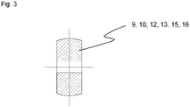
- FIG. 3 shows a cross-sectional view of one of the deflection rollers 9, 10, 12, 13, 14, 15.
- the first, second and third deflection rollers 9, 10, 12, 13, 14, 15 have a crowning on their running surface along their axis of rotation, namely a bulging of the running surface towards the middle of the running surface.
- at least some of the first, second and third deflection rollers 9, 10, 12, 13, 14, 15 can also be provided with a straight running surface along their axis of rotation.
- the gas pressure spring is provided between the first support element 3 and the second support element 3 ′ and is designed to apply the driving or supporting force to the first or second cable-type synchronization element 11 , 14 .
- the synchronization device is not provided with cable-like synchronization elements, but the synchronization takes place, for example, via an axle with bevel gears on both sides and respective threaded spindles.
Landscapes
- Machine Tool Units (AREA)
- Transmission Devices (AREA)
- Invalid Beds And Related Equipment (AREA)
- Wind Motors (AREA)
Abstract
Description
- Die Erfindung betrifft eine Stützvorrichtung für einen höhenverstellbaren Tisch, insbesondere für einen höhenverstellbaren Tisch mit mehreren Stützelementen.
- Im Stand der Technik sind höhenverstellbare Tische bekannt, die, um Lasten, die auf einer Tischplatte des höhenverstellbaren Tisches aufgestellt sind, sicher und zuverlässig tragen und anheben zu können, mehrere höhenverstellbaren Tischbeine, die im Folgenden auch als Stützelemente bezeichnet werden, aufweisen.
- Dabei besteht das Problem, dass Bauteile der höhenverstellbaren Tischbeine verkanten und sich somit verklemmen können, wenn sich die Tischbeine nicht synchron bewegen.
- Ferner gibt es zwei Normen für Schreibtische, in denen sich eine minimal einstellbare Höhe der Arbeitsfläche und ein erforderlicher Hub unterscheiden. Die größere der Anforderungen der beiden Normen kann mit 2-teiligen Hubsäulen, insbesondere mit eingebauten Gasdruckfedern, nicht erfüllt werden, da die geforderte minimal einstellbare Höhe der Arbeitsfläche kleiner als das notwendige Einbaumaß für eine Gasfeder mit dem geforderten Mindesthub ist.
- Der Erfindung liegt die Aufgabe zugrunde, die obigen Probleme auszuräumen und eine Stützvorrichtung für einen höhenverstellbaren Tisch bereitzustellen, die über einen gesamten Verstellbereich für eine ergonomische Arbeitshöhe der Tischplatte eine zuverlässige Funktion des höhenverstellbaren Tisches ermöglicht.
- Die Aufgabe wird durch eine Stützvorrichtung gemäß Anspruch 1 und einen höhenverstellbaren Tisch gemäß Anspruch 15 gelöst. Vorteilhafte Weiterentwicklungen der Erfindung sind in den abhängigen Ansprüchen enthalten.
- Gemäß einem Aspekt der Erfindung weist eine Stützvorrichtung für einen höhenverstellbaren Tisch ein erstes Stützelement und mindestens ein zweites Stützelement auf, wobei das erste Stützelement und das mindestens eine zweite Stützelement jeweils ein erstes Auslegebauteil, ein zweites Auslegebauteil und ein drittes Auslegebauteil aufweisen. Das erste Auslegebauteil, das zweite Auslegebauteil und das dritte Auslegebauteil sind relativ zueinander verschiebbar angeordnet, um jeweils eine Längenänderung des ersten Stützelements und des mindestens einen zweiten Stützelements zu bewirken. Das zweite Auslegebauteil ist in einer Richtung der Längenänderung zwischen dem ersten Auslegebauteil und dem dritten Auslegebauteil angeordnet, und das erste Auslegebauteil, das zweite Auslegebauteil und das dritte Auslegebauteil sind so miteinander gekoppelt, dass, bei der Längenänderung des ersten Stützelements und des mindestens einen zweiten Stützelements, eine Verschiebung des zweiten Auslegebauteils zu dem ersten Auslegebauteil in einer Richtung parallel zu der Längenänderung synchron eine Verschiebung des dritten Auslegebauteil zu dem zweiten Auslegebauteil in der gleichen Richtung bewirkt wird. Die Stützvorrichtung weist ferner eine Synchronisationseinrichtung auf, die dazu ausgebildet ist, zwischen dem ersten Stützelement und dem mindestens einen zweiten Stützelement, die Verschiebung des zweiten Auslegebauteils zu dem ersten Auslegebauteil oder die Verschiebung des dritten Auslegebauteils zu dem zweiten Auslegebauteil zu synchronisieren.
- Durch die definierte Bewegung der einzelnen Auslegebauteile zueinander wird ermöglicht, dass auf die Stützelemente aufgebrachte Biegemomente, die beispielsweise durch Aufstützen am Rand einer Tischplatte während einer Höhenverstellung oder durch größere exzentrisch aufgestellte Lasten auf der Tischplatte entstehen, aufgefangen werden können, ohne dass Führungen oder Gleitstücke, die ein möglichst spielfreies Ineinanderfahren der Auslegebauteile ermöglichen sollen, übermäßig belastet werden. Diese definierte Bewegung wird entsprechend synchronisiert ausgeführt, sodass ein Verkanten von den mehreren Stützelementen nicht auftreten kann.
- In einer vorteilhaften Ausgestaltung der Stützvorrichtung sind ein Ausmaß der Verschiebung zwischen dem zweiten Auslegebauteil und dem ersten Auslegebauteil und ein Ausmaß der Verschiebung zwischen dem dritten Auslegebauteil und dem zweiten Auslegebauteil identisch.
- Durch die identischen Verschiebungsausmaße zwischen dem zweiten Auslegebauteil und dem ersten Auslegebauteil und zwischen dem dritten Auslegebauteil und dem zweiten Auslegebauteil kann die Belastung auf die Führungen oder Gleitstücke minimiert werden.
- In einer weiteren vorteilhaften Ausgestaltung der Stützvorrichtung weist die Stützvorrichtung ein endloses seilzugartiges Element und zwei dritte Umlenkrollen, die in der Richtung der Längenänderung des ersten Stützelements und des mindestens einen zweiten Stützelements beabstandet angeordnet sind und mit dem zweiten Auslegebauteil verbunden sind, auf, wobei das endlose seilzugartige Element dazu ausgebildet ist, dass es durch die zwei dritten Umlenkrollen spielfrei umgelenkt wird und jeweils ein Abschnitt des endlosen seilzugartigen Elements in der Richtung der Längenänderung des ersten Stützelements und des mindestens einen zweiten Stützelements zwischen den zwei dritten Umlenkrollen mit dem ersten Auslegebauteil und dem dritten Auslegebauteil verbunden ist.
- Durch diese Anordnung können insbesondere die identischen Verschiebungsausmaße zwischen dem zweiten Auslegebauteil und dem ersten Auslegebauteil und zwischen dem dritten Auslegebauteil und dem zweiten Auslegebauteil einfach realisiert werden.
- Gemäß einer weiteren vorteilhaften Ausgestaltung der Stützvorrichtung ist das seilzugartige Element ein Stahlband.
- Durch die Verwendung des Stahlbandes mit einer hohen Zugfestigkeit ist die Auslegung mit einem geringen Durchmesser möglich, was auch eine Verwendung von Umlenkrollen mit geringen Abmessungen ermöglicht, sodass Bauraum eingespart werden kann. Außerdem ist aufgrund einer geringen Dehnung des Stahlbands eine genau definierte Bewegung der einzelnen Auslegebauteile zueinander möglich.
- In einer weiteren vorteilhaften Ausgestaltung der Stützvorrichtung weisen die dritten Umlenkrollen entlang ihrer Drehachse eine Balligkeit an ihrer Lauffläche auf.
- Durch die Balligkeit, nämlich eine Auswölbung der Lauffläche zu der Mitte der Lauffläche hin, erfolgt beim Lauf des Stahlbands eine Eigenzentrierung, sodass ein zuverlässiger Betrieb ohne zusätzliche Zentriereinrichtungen möglich ist.
- Bei einer weiteren vorteilhaften Ausgestaltung der Stützvorrichtung weist die Synchronisationseinrichtung ein erstes seilzugartiges Synchronisationselement auf, das an einem Ende an einem der Auslegebauteile des ersten Stützelements befestigt ist und an dem anderen Ende an dem gleichen der Auslegebauteile des mindestens zweiten Stützelements befestigt ist, und erste Umlenkrollen, die jeweils an einem anderen der Auslegebauteile des ersten Stützelements und des mindestens zweiten Stützelements befestigt sind, wobei das andere der Auslegebauteile des ersten Stützelements und des mindestens einen zweiten Stützelements jeweils das gleiche Auslegebauteil ist, und eine Umlenkung des ersten seilzugartigen Synchronisationselements mittels der ersten Umlenkrollen in einer Art erfolgt, dass eine erste Relativverschiebung zwischen zwei der Auslegebauteile des ersten Stützelements eine synchrone Relativverschiebung zwischen den zwei gleichen Auslegebauteilen des mindestens einen zweiten Stützelements zur Folge hat.
- Durch diese Anordnung kann die Relativverschiebung zwischen zwei gleichen Auslegebauteilen zwischen den zwei Stützelementen einfach realisiert werden.
- Gemäß einer weiteren vorteilhaften Ausgestaltung der Stützvorrichtung weist die Synchronisationseinrichtung ein zweites seilzugartiges Synchronisationselement, das an einem Ende an einem der Auslegebauteile des ersten Stützelements befestigt ist und an dem anderen Ende an dem gleichen der Auslegebauteile des mindestens zweiten Stützelements befestigt ist, und zweite Umlenkrollen, die jeweils an dem anderen der Auslegebauteile des ersten Stützelements und des mindestens zweiten Stützelements befestigt sind, wobei das andere der Auslegebauteile des ersten Stützelements und des mindestens einen zweiten Stützelements jeweils das gleiche Auslegebauteil ist, auf. Eine Umlenkung des zweiten seilzugartigen Synchronisationselements mittels der zweiten Umlenkrollen erfolgt in einer Art, dass eine entgegengesetzte Relativverschiebung zwischen zwei der Auslegebauteile des ersten Stützelements entgegengesetzt zu der ersten Relativverschiebung in dem ersten Stützelement eine synchrone entgegengesetzte Relativverschiebung zwischen den zwei gleichen Auslegebauteilen des mindestens einen zweiten Stützelements zur Folge hat.
- Durch diese Anordnung kann auch die entgegengesetzte Relativverschiebung zwischen zwei gleichen Auslegebauteilen zwischen den zwei Stützelementen einfach realisiert werden.
- In einer weiteren vorteilhaften Ausgestaltung der Stützvorrichtung ist das erste und zweite seilzugartige Element jeweils ein Stahlband.
- Die Verwendung des Stahlbandes ermöglicht eine Verwendung von Umlenkrollen mit geringem Durchmesser und aufgrund einer geringen Dehnung des Stahlbands ist eine genau definierte Synchronisation der Relativbewegung zwischen dem ersten Stützelement und dem zweiten Stützelement zueinander möglich.
- Bei einer weiteren vorteilhaften Ausgestaltung der Stützvorrichtung weisen die ersten Umlenkrollen und zweiten Umlenkrollen entlang ihrer Drehachse eine Balligkeit an ihrer Lauffläche auf.
- Dadurch erfolgt beim Lauf des Stahlbands eine Eigenzentrierung, sodass ein zuverlässiger Betrieb ohne zusätzliche Zentriereinrichtungen möglich ist.
- Gemäß einer weiteren vorteilhaften Ausgestaltung der Stützvorrichtung weist die Stützvorrichtung ein Antriebs- oder Unterstützungselement auf, das die Längenänderungen des ersten Stützelements und des mindestens einen zweiten Stützelements antreibt oder unterstützt.
- Durch die Verwendung des Antriebs- oder Unterstützungselements kann die Tischplatte, insbesondere bei einer hohen Zuladung, ohne oder mit einem geringen Muskelkraftaufwand verstellt werden.
- In einer weiteren vorteilhaften Ausgestaltung der Stützvorrichtung ist das Antriebs- oder Unterstützungselement eine Gasdruckfeder.
- Die Gasdruckfeder als das Antriebs- oder Unterstützungselement hat einen geringen Platzbedarf und kann kostengünstig bereitgestellt werden.
- Bei einer weiteren vorteilhaften Ausgestaltung der Stützvorrichtung ist die Gasdruckfeder in mindestens einem von dem ersten und dem mindestens einen zweiten Stützelement angeordnet.
- Durch die Koppelung der Auslegebauteile ist es möglich, eine Gasdruckfeder in dem Stützelement einzubauen, da die Hublänge der Gasdruckfedern geringer als die maximale Längenänderung des Stützelements sein kann. Dadurch hat die Gasdruckfeder in ihrem eingeschobenen Zustand eine Länge, die geringer als der zur Verfügung stehende Bauraum ist. Somit werden eine kompakte Bauform und ein geringerer gesamter Montageaufwand ermöglicht, da das Stützelement mit der Gasfeder bereits einfach vormontiert werden kann und somit ein Aufwand bei der Endmontage verringert wird.
- Gemäß einer anderen vorteilhaften Ausgestaltung der Stützvorrichtung ist die Gasdruckfeder zwischen dem ersten Stützelement und dem mindestens einen zweiten Stützelement vorgesehen und ist dazu ausgebildet, eine Antriebs- oder Unterstützungskraft auf das seilzugartige Synchronisationselement aufzubringen.
- Gemäß dieser Ausgestaltung ist es möglich, die Stützelemente mit einem geringeren Querschnitt zu versehen, da der Platzbedarf der Gasfeder in dem Stützelement entfällt, so dass gestalterische Anforderungen einfacher umgesetzt werden können.
- Bei weiteren vorteilhaften Ausgestaltungen ist das Antriebs- oder Unterstützungselement dazu ausgebildet, dass es eine Antriebs- oder Unterstützungskraft zwischen dem ersten Auslegebauteil und dem zweiten Auslegebauteil oder zwischen dem zweiten Auslegebauteil und dem dritten Auslegebauteil aufbringt.
- Durch ein solches Aufbringen der Antriebs- oder Unterstützungskraft kann das Antriebs- oder Unterstützungselement mit einem geringeren Verfahrweg und damit mit einem erforderlichen Bauraum mit einer geringeren Länge konzipiert werden, da sich durch die Koppelung des ersten, zweiten und dritten Auslegebauteils eine größere Längenänderung der Stützelemente als die Längenänderung des Antriebs- oder Unterstützungselement ergibt.
- Gemäß einem weiteren Aspekt der Erfindung ist ein höhenverstellbarer Tisch mit einer Stützvorrichtung versehen.
- Bei einem solchen höhenverstellbaren Tisch wird ermöglicht, dass auf die Stützelemente aufgebrachte Biegemomente, beispielsweise durch Aufstützen am Rand einer Tischplatte während einer Höhenverstellung oder durch größere exzentrisch aufgestellte Lasten auf der Tischplatte, aufgefangen werden können, ohne dass Führungen oder Gleitstücke, die ein möglichst spielfreies Ineinanderfahren der Auslegebauteile ermöglichen, übermäßig belastet werden. Ferner wird die Bewegung zur Höhenverstellung synchronisiert ausgeführt, so dass ein Verkanten von den mehreren Stützelementen nicht auftreten kann.
- Nachfolgend wird die Erfindung anhand von Ausführungsbeispielen unter Bezugnahme auf die beigefügten Zeichnungen erläutert.
- Insbesondere zeigt
- Fig. 1
- eine Prinzipdarstellung eines erfindungsgemäßen höhenverstellbaren Tisches;
- Fig. 2
- eine Prinzipdarstellung eines Stützelements mit einer Kopplungseinrichtung eines ersten, zweiten und dritten Auslegebauteils; und
- Fig. 3
- eine Querschnittsansicht einer Umlenkrolle.
-
Fig. 1 zeigt eine Prinzipdarstellung eines erfindungsgemäßen höhenverstellbaren Tisches 1. - Der höhenverstellbare Tisch 1 weist eine Tischplatte 2 sowie eine Stützvorrichtung mit einem ersten Stützelement 3 und einem zweiten Stützelement 3' auf. Die Stützelemente 3, 3' bilden hier Tischbeine, bei denen eine Längenänderung L möglich ist, um die Tischplatte 2 in ihrer Höhe zu verstellen. Die Stützelemente 3, 3' sind mittels einer Querstrebe 4 miteinander verbunden und in einem geeigneten Abstand an der Tischplatte 2 befestigt. In einer alternativen Ausführungsform sind die Stützelemente 3, 3' einzeln an der Tischplatte befestigt, ohne die Querstrebe 4 aufzuweisen. In weiteren alternativen Ausführungsformen sind mehr als zwei Stützelemente 3, 3' vorgesehen.
-
Fig. 1a zeigt eine vergrößerte Prinzipdarstellung des Stützelements 3. - Die Stützelemente 3, 3' weisen jeweils ein erstes Auslegebauteil 5, 5', ein zweites Auslegebauteil 6, 6' und ein drittes Auslegebauteil 7, 7' auf. Das erste Auslegebauteil 5, 5', das zweite Auslegebauteil 6, 6' und das dritte Auslegebauteil 7, 7' sind relativ zueinander verschiebbar angeordnet, um jeweils die Längenänderung L des ersten Stützelements 3 und des zweiten Stützelements 3' zu bewirken. Das zweite Auslegebauteil 6, 6' ist in Richtung der Längenänderung L zwischen dem ersten Auslegebauteil 5, 5' und dem dritten Auslegebauteil 7, 7' angeordnet. Das erste Auslegebauteil 5, 5' ist mit der Tischplatte 2 verbunden. Das dritte Auslegebauteil 7, 7' ist mit einem Tischfuß (nicht gezeigt) so verbunden, dass der höhenverstellbare Tisch 1 auf einem Boden stehen kann, ohne zu kippen.
- Die Stützvorrichtung weist ferner in jedem der Stützelemente 3, 3' ein Antriebs- oder Unterstützungselement 17, 17' auf, das die Längenänderung L des ersten Stützelements 3 und des zweiten Stützelements 3' antreibt oder unterstützt. Das Unterstützungselement 17, 17' unterstützt beispielsweise eine menschliche Muskelkraft bei der Höhenverstellung der Tischplatte, um den Kraftaufwand zu reduzieren. Das Antriebselement führt die Höhenverstellung der Tischplatte hingegen ohne menschliche Muskelkraft aus.
- In dieser Ausführungsform ist das Antriebs- oder Unterstützungselement 17, 17' eine Gasdruckfeder. In alternativen Ausführungsformen kann beispielsweise ein Hydraulikzylinder oder ein elektromotorisch betriebener Linearantrieb vorgesehen sein. In weiteren alternativen Ausführungsformen ist nicht für jedes der Stützelemente 3, 3' eines der Antriebs- oder Unterstützungselemente 17, 17' vorgesehen, sondern lediglich beispielsweise ein einziges Antriebs- oder Unterstützungselement 17, 17' für eines der Stützelemente 3, 3'.
- Die Gasdruckfedern sind in den Stützelementen 3, 3' angeordnet. In alternativen Ausführungsformen sind die Gasdruckfedern außerhalb der Stützelemente 3, 3', angeordnet.
- Das Antriebs- oder Unterstützungselement 17, 17' ist dazu ausgebildet, dass es eine Antriebs- oder Unterstützungskraft zwischen dem ersten Auslegebauteil 5, 5' und dem zweiten Auslegebauteil 6, 6' aufbringt. In einer alternativen Ausführungsform ist das Antriebs- oder Unterstützungselement 17, 17' dazu ausgebildet, dass es eine Antriebs- oder Unterstützungskraft zwischen dem zweiten Auslegebauteil 6, 6' und dem dritten Auslegebauteil 7, 7' aufbringt.
- Die Stützvorrichtung weist ferner eine Synchronisationseinrichtung auf, die dazu ausgebildet ist, zwischen dem ersten Stützelement 3 und dem zweiten Stützelement 3', die Verschiebung des zweiten Auslegebauteils 6, 6' zu dem ersten Auslegebauteil 5, 5' oder die Verschiebung des dritten Auslegebauteils 7, 7' zu dem zweiten Auslegebauteil 6, 6' zu synchronisieren.
- Die Synchronisationseinrichtung weist ein erstes seilzugartiges Synchronisationselement 11 auf, das mit einem Ende an einem der Auslegebauteile, in dieser Ausführungsform an dem zweiten Auslegebauteil 6, des ersten Stützelements 3 befestigt ist und an dem anderen Ende an dem gleichen der Auslegebauteile, hier ebenfalls mit dem zweiten Auslegebauteil 6', des zweiten Stützelements 3' befestigt ist. Ferner weist die Synchronisationseinrichtung zwei erste Umlenkrollen 12, 13 auf, die jeweils an einem anderen der Auslegebauteile, in dieser Ausführungsform an dem ersten Auslegebauteil 5, 5', befestigt sind. Eine Umlenkung des ersten seilzugartigen Synchronisationselements 11 erfolgt mittels der zwei ersten Umlenkrollen 12, 13 in einer Art, dass die Relativverschiebung RV zwischen zwei der Auslegebauteile, in dieser Ausführungsform zwischen dem zweiten Auslegebauteil 6 und dem ersten Auslegebauteil 5, des ersten Stützelements 3 eine synchrone Relativverschiebung RV zwischen den zwei gleichen Auslegebauteilen, in dieser Ausführungsform zwischen dem zweiten Auslegebauteil 6' und dem ersten Auslegebauteil 5', des zweiten Stützelements 3' zur Folge hat.
- In alternativen Ausführungsformen können das erste seilzugartige Synchronisationselement 11 und die zwei ersten Umlenkrollen 12, 13 auch an anderen Auslegebauteil 5, 5', 6, 6', 7, 7' des ersten Stützelements 3 und des zweiten Stützelements 3' angebracht sein, wobei wesentlich ist, dass die beiden Auslegebauteile 5, 5', 6, 6', 7, 7' jeweils unterschiedlich sind und das Auslegebauteil 5, 5', 6, 6', 7, 7' an dem ersten Stützelement 3 und dem zweiten Stützelement 3' jeweils das gleiche Auslegebauteil 5, 5', 6, 6', 7, 7' ist.
- Die Synchronisationseinrichtung weist ferner ein zweites seilzugartiges Synchronisationselement 14 auf, das an einem Ende an einem der Auslegebauteile, in dieser Ausführungsform an dem zweiten Auslegebauteil 6, des ersten Stützelements 3 befestigt ist und an dem anderen Ende an dem gleichen der Auslegebauteile, hier ebenfalls an dem zweiten Auslegebauteil 6', des zweiten Stützelements 3' befestigt ist. Ferner weist die Synchronisationseinrichtung zwei zweite Umlenkrollen 15, 16 auf, die jeweils an einem anderen der Auslegebauteile, in dieser Ausführungsform an dem ersten Auslegebauteil 5,5', befestigt sind. Eine Umlenkung des zweiten seilzugartigen Synchronisationselements 14 erfolgt mittels der zwei zweiten Umlenkrollen 15, 16 in einer Art, dass eine entgegengesetzte Relativverschiebung RV' zwischen zwei der Auslegebauteile, in dieser Ausführungsform zwischen dem dritten Auslegebauteil 7 und dem ersten Auslegebauteil 5, des ersten Stützelements 3 eine entgegengesetzte Relativverschiebung RV' zwischen den zwei gleichen Auslegebauteilen, in dieser Ausführungsform zwischen dem zweiten Auslegebauteil 6' und dem ersten Auslegebauteil 5', des zweiten Stützelement 3' zur Folge hat.
- In alternativen Ausführungsformen können das zweite seilzugartige Synchronisationselement 14 und die zwei zweiten Umlenkrollen 15, 16 auch an anderen Auslegebauteilen 5, 5', 6, 6', 7, 7' des ersten Stützelements 3 und des zweiten Stützelements 3' angebracht sein, wobei wesentlich ist, dass die beiden Auslegebauteile 5, 5', 6, 6', 7, 7' von einem der Stützelemente 3, 3' jeweils unterschiedlich sind und das Auslegebauteil 5, 5', 6, 6', 7, 7' an dem ersten Stützelement 3 und dem zweiten Stützelement 3' jeweils das gleiche Auslegebauteil 5, 5', 6, 6', 7, 7' ist.
- Das erste seilzugartige Synchronisationselement 11 und das zweite seilzugartige Synchronisationselement 14 sind jeweils als ein Stahlband ausgeführt. In alternativen Ausführungsformen können das erste seilzugartige Synchronisationselement 11 und das zweite seilzugartige Synchronisationselement 14 auch beispielsweise jeweils als ein Kunststoffband oder ein Stahlseil ausgeführt sein.
-
Fig. 2 zeigt eine Prinzipdarstellung von einem der Stützelemente 3 mit einer Kopplungseinrichtung des ersten Auslegebauteils 5, des zweiten Auslegebauteils 6 und des dritten Auslegebauteils 7. Das erste Auslegebauteil 5, das zweite Auslegebauteil 6 und das dritte Auslegebauteil 7 sind so miteinander gekoppelt, dass, bei der Längenänderung L des ersten Stützelements 3, eine Verschiebung des zweiten Auslegebauteils 6 zu dem ersten Auslegebauteil 5 in einer Richtung parallel zu der Längenänderung L synchron eine Verschiebung des dritten Auslegebauteils 7 zu dem zweiten Auslegebauteil 6 in der gleichen Richtung bewirkt. Das zweite Stützelement 3' weist eine identische Kopplungseinrichtung auf. - Als die Kopplungseinrichtung weist die Stützvorrichtung 3 ein endloses seilzugartiges Element 8 auf. Ferner weist die Stützvorrichtung 3, zwei dritte Umlenkrollen 9, 10 auf, die in der Richtung der Längenänderung L beabstandet angeordnet und mit dem zweiten Auslegebauteil 6 verbunden sind, auf. Das endlose seilzugartige Element 8 ist dazu ausgebildet, dass es durch die zwei dritten Umlenkrollen 9, 10 spielfrei umgelenkt wird und jeweils ein Abschnitt 8.1, 8.2 in der Richtung der Längenänderung L zwischen den zwei dritten Umlenkrollen 9, 10 ist mit dem ersten Auslegebauteil 5 und dem dritten Auslegebauteil 7 verbunden. Hierbei ist der Abschnitt 8.1 mit dem ersten Auslegebauteil 5 und der Abschnitt 8.2 mit dem dritten Auslegebauteil 7 verbunden.
- Ein Ausmaß der Verschiebung zwischen dem zweiten Auslegebauteil 6 und dem ersten Auslegebauteil 5 und ein Ausmaß der Verschiebung zwischen dem dritten Auslegebauteil 7 und dem zweiten Auslegebauteil 6 sind in dieser Ausführungsform identisch.
- In alternativen Ausführungsformen kann, wenn eine Kopplung der unterschiedlichen Auslegebauteile 5, 5', 6, 6', 7, 7' beispielsweise über miteinander gekoppelte Gewindestangen mit unterschiedlichen Steigungen erfolgt, das Ausmaß der Verschiebung zwischen dem zweiten Auslegebauteil 6, 6' und dem ersten Auslegebauteil 5, 5' und das Ausmaß der Verschiebung zwischen dem dritten Auslegebauteil 7, 7' und dem zweiten Auslegebauteil 6, 6' unterschiedlich sein.
- Das seilzugartige Element 8 ist als ein Stahlband ausgeführt. In alternativen Ausführungsformen kann das seilzugartige Element 8 auch beispielsweise als ein Kunststoffband oder ein Stahlseil ausgeführt sein.
-
Fig. 3 zeigt eine Querschnittsansicht einer der Umlenkrollen 9, 10, 12, 13, 14, 15. - Die ersten, zweiten und dritten Umlenkrollen 9, 10, 12, 13, 14, 15 weisen entlang ihrer Drehachse eine Balligkeit an ihrer Lauffläche, nämlich eine Auswölbung der Lauffläche zu der Mitte der Lauffläche hin, auf. In alternativen Ausführungsformen können zumindest einige von den ersten, zweiten und dritten Umlenkrollen 9, 10, 12, 13, 14, 15 auch mit einer geraden Lauffläche entlang ihrer Drehachse versehen sein.
- In einer alternativen Ausführungsform ist die Gasdruckfeder zwischen dem ersten Stützelement 3 und dem zweiten Stützelement 3' vorgesehen und dazu ausgebildet, die Antriebs- oder Unterstützungskraft auf das erste oder zweite Seilzug-artige Synchronisationselement 11, 14 aufzubringen.
- In einer weiteren alternativen Ausführungsform ist die Synchronisationseinrichtung nicht mit seilzugartigen Synchronisationselementen versehen, sondern die Synchronisation erfolgt beispielsweise über eine Achse mit beidseitigem Kegelradgetriebe und jeweiligen Gewindespindeln.
- Alle in der Beschreibung, den nachfolgenden Ansprüchen und der Zeichnung dargestellten Merkmale können sowohl einzeln als auch in beliebiger Kombination miteinander erfindungswesentlich sein.
Claims (15)
- Stützvorrichtung für einen höhenverstellbaren Tisch (1), aufweisend:ein erstes Stützelement (3) und mindestens ein zweites Stützelement (3'), wobei das erste Stützelement (3) und das mindestens eine zweite Stützelement (3') jeweilsein erstes Auslegebauteil (5, 5'), ein zweites Auslegebauteil (6, 6') und ein drittes Auslegebauteil (7, 7') aufweisen, wobeidas erste Auslegebauteil (5, 5'), das zweite Auslegebauteil (6, 6') und das dritte Auslegebauteil (7, 7') relativ zueinander verschiebbar angeordnet sind, um jeweils eine Längenänderung (L) des ersten Stützelements (3) und des mindestens einen zweiten Stützelements (3') zu bewirken,das zweite Auslegebauteil (6, 6') in einer Richtung der Längenänderung (L) zwischen dem ersten Auslegebauteil (5, 5') und dem dritten Auslegebauteil (7, 7') angeordnet ist,das erste Auslegebauteil (5, 5'), das zweite Auslegebauteil (6, 6') und das dritte Auslegebauteil (7, 7') so miteinander gekoppelt sind, dass, bei der Längenänderung (L) des ersten Stützelements (3) und des mindestens einen zweiten Stützelements (3'), eine Verschiebung des zweiten Auslegebauteils (6, 6') zu dem ersten Auslegebauteil (5, 5') in einer Richtung parallel zu der Längenänderung (L) synchron eine Verschiebung des dritten Auslegebauteil (7, 7') zu dem zweiten Auslegebauteil (6, 6') in der gleichen Richtung bewirkt,und eine Synchronisationseinrichtung, die dazu ausgebildet ist, zwischen dem ersten Stützelement (3) und dem mindestens einen zweiten Stützelement (3'), die Verschiebung des zweiten Auslegebauteils (6, 6') zu dem ersten Auslegebauteil (5, 5') oder die Verschiebung des dritten Auslegebauteils (7, 7') zu dem zweiten Auslegebauteil (6, 6') zu synchronisieren.
- Stützvorrichtung gemäß Anspruch 1, wobei
ein Ausmaß der Verschiebung zwischen dem zweiten Auslegebauteil (6, 6') und dem ersten Auslegebauteil (5, 5') und ein Ausmaß der Verschiebung zwischen dem dritten Auslegebauteil (7, 7') und dem zweiten Auslegebauteil (6, 6') identisch sind. - Stützvorrichtung gemäß einem der Ansprüche 1 oder 2, wobei
die Stützvorrichtung
ein endloses seilzugartiges Element (8) und
zwei dritte Umlenkrollen (9, 10), die in der Richtung der Längenänderung (L) beabstandet angeordnet sind und mit dem zweiten Auslegebauteil (6, 6') verbunden sind, aufweist, wobei
das endlose seilzugartige Element (8) dazu ausgebildet ist, dass es durch die zwei dritten Umlenkrollen (9, 10) spielfrei umgelenkt wird und jeweils ein Abschnitt (8.1, 8.2) des endlosen seilzugartigen Elements (8) in der Richtung der Längenänderung (L) zwischen den zwei dritten Umlenkrollen (9, 10) mit dem ersten Auslegebauteil (5, 5') und dem dritten Auslegebauteil (7, 7') verbunden ist. - Stützvorrichtung gemäß Anspruch 3, wobei
das seilzugartige Element (8) ein Stahlband ist. - Stützvorrichtung gemäß einem der Ansprüche 3 oder 4, wobei
die dritten Umlenkrollen (9, 10) entlang ihrer Drehachse eine Balligkeit an ihrer Lauffläche aufweisen. - Stützvorrichtung gemäß einem der Ansprüche 1 bis 5, wobei
die Synchronisationseinrichtung aufweist:ein erstes seilzugartiges Synchronisationselement (11), das an einem Ende an einem der Auslegebauteile (5, 6, 7) des ersten Stützelements (3) befestigt ist und an dem anderen Ende an dem gleichen der Auslegebauteile (5', 6', 7') des mindestens einen zweiten Stützelements (3') befestigt ist, undzwei erste Umlenkrollen (12, 13), die jeweils an einem anderen der Auslegebauteile (5, 5', 6, 6', 7, 7') des ersten Stützelements (3) und des mindestens zweiten Stützelements (3, 3') befestigt sind, wobei das andere der Auslegebauteile (5, 5', 6, 6', 7, 7') des ersten Stützelements (3) und des mindestens einen zweiten Stützelements (3') jeweils das gleiche Auslegebauteil (5, 5', 6, 6', 7, 7') ist, undeine Umlenkung des ersten seilzugartigen Synchronisationselements (11) mittels der ersten Umlenkrollen (12, 13) in einer Art erfolgt, dass eine erste Relativverschiebung (RV) zwischen zwei der Auslegebauteile (5, 6, 7) des ersten Stützelements (3) eine synchrone Relativverschiebung (RV) zwischen den zwei gleichen Auslegebauteilen (5', 6', 7') des mindestens einen zweiten Stützelements (3') zur Folge hat. - Stützvorrichtung gemäß Anspruch 6, wobei
die Synchronisationseinrichtung aufweist:ein zweites seilzugartiges Synchronisationselement (14), das an einem Ende an einem der Auslegebauteile (5, 6, 7) des ersten Stützelements (3) befestigt ist und an dem anderen Ende an dem gleichen der Auslegebauteile des mindestens einen zweiten Stützelements befestigt ist, undzweite Umlenkrollen (15, 16), die jeweils an dem anderen der Auslegebauteile (5, 5', 6, 6', 7, 7') des ersten Stützelements (3) und des mindestens einen zweiten Stützelements (3') befestigt sind, wobei das andere der Auslegebauteile (5, 5', 6, 6', 7, 7') des ersten Stützelements (3) und des mindestens einen zweiten Stützelements (3') jeweils das gleiche Auslegebauteil (5, 5', 6, 6', 7, 7') ist, wobeieine Umlenkung des zweiten seilzugartigen Synchronisationselements (14) mittels der zweiten Umlenkrollen, (15, 16) in einer Art erfolgt, dass eine entgegengesetzte Relativverschiebung (RV') zwischen zwei der Auslegebauteile (5, 6, 7) des ersten Stützelements (3) entgegengesetzt zu der ersten Relativverschiebung (RV) in dem ersten Stützelement (3) eine synchrone entgegengesetzte Relativverschiebung (RV') zwischen den zwei gleichen Auslegebauteilen (5', 6', 7') des mindestens einen zweiten Stützelements (3) zur Folge hat. - Stützvorrichtung gemäß Anspruch 7, wobei
das erste seilzugartige Synchronisationselement (11) und das zweite seilzugartige Synchronisationselement (14) jeweils ein Stahlband ist. - Stützvorrichtung gemäß einem der Ansprüche 7 oder 8, wobei
die ersten Umlenkrollen (12, 13) und zweiten Umlenkrollen (15, 16) entlang ihrer Drehachse eine Balligkeit an ihrer Lauffläche aufweisen - Stützvorrichtung gemäß einem der vorangehenden Ansprüche, wobei
die Stützvorrichtung ein Antriebs- oder Unterstützungselement (17, 17') aufweist, das die Längenänderung (L) des ersten Stützelements (3) und des mindestens einen zweiten Stützelements (3') antreibt oder unterstützt. - Stützvorrichtung gemäß Anspruch 10, wobei
das Antriebs- oder Unterstützungselement (17, 17') eine Gasdruckfeder ist. - Stützvorrichtung gemäß Anspruch 11, wobei
die Gasdruckfeder in mindestens einem von dem ersten Stützelement (3) und dem mindestens einen zweiten Stützelement (3') angeordnet ist. - Stützvorrichtung gemäß einem der Ansprüche 7 bis 9 und 11, wobei
die Gasdruckfeder zwischen dem ersten Stützelement (3) und dem mindestens einen zweiten Stützelement (3') vorgesehen ist und dazu ausgebildet ist, eine Antriebs- oder Unterstützungskraft auf das seilzugartige Synchronisationselement (11, 14) aufzubringen. - Stützvorrichtung gemäß einem der Ansprüche 10 bis 13, wobei
das Antriebs- oder Unterstützungselement (17, 17') dazu ausgebildet ist, dass es eine Antriebs- oder Unterstützungskraft zwischen dem ersten Auslegebauteil (5, 5') und dem zweiten Auslegebauteil (6, 6') oder zwischen dem zweiten Auslegebauteil (6, 6') und dritten Auslegebauteil (7, 7') aufbringt. - Höhenverstellbarer Tisch (1) mit einer Stützvorrichtung gemäß einem der vorangehenden Ansprüche.
Applications Claiming Priority (1)
| Application Number | Priority Date | Filing Date | Title |
|---|---|---|---|
| DE102020211930.9A DE102020211930A1 (de) | 2020-09-23 | 2020-09-23 | Stützvorrichtung für ein höhenverstellbares Tischgestell |
Publications (2)
| Publication Number | Publication Date |
|---|---|
| EP3973817A1 true EP3973817A1 (de) | 2022-03-30 |
| EP3973817B1 EP3973817B1 (de) | 2024-04-24 |
Family
ID=76034589
Family Applications (1)
| Application Number | Title | Priority Date | Filing Date |
|---|---|---|---|
| EP21175115.1A Active EP3973817B1 (de) | 2020-09-23 | 2021-05-20 | Stützvorrichtung für ein höhenverstellbares tischgestell |
Country Status (5)
| Country | Link |
|---|---|
| US (1) | US11607034B2 (de) |
| EP (1) | EP3973817B1 (de) |
| CN (1) | CN114246416A (de) |
| DE (1) | DE102020211930A1 (de) |
| DK (1) | DK3973817T3 (de) |
Families Citing this family (2)
| Publication number | Priority date | Publication date | Assignee | Title |
|---|---|---|---|---|
| HU231339B1 (hu) * | 2019-08-15 | 2023-01-28 | Koch Anna Mária dr. | Mozgató rendszer, valamint ilyen mozgató rendszert tartalmazó multifunkciós asztal |
| DE102024207550A1 (de) * | 2024-08-08 | 2026-02-12 | Kesseböhmer Holding Kg | Tischgestell für einen höhenverstellbaren Tisch und höhenverstellbarer Tisch mit einem solchen Tischgestell |
Citations (4)
| Publication number | Priority date | Publication date | Assignee | Title |
|---|---|---|---|---|
| WO2008145399A1 (de) * | 2007-05-31 | 2008-12-04 | Kesseböhmer Produktions GmbH & Co. KG | Höhenverstellbare säule, insbesondere für tische |
| EP1987734B1 (de) * | 2007-04-30 | 2010-12-22 | Kesseböhmer Produktions GmbH + Co. KG | Vorrichtung zur Bewegungssynchronisierung von Stützelementen |
| EP2213198B1 (de) * | 2009-02-02 | 2012-11-14 | Veyhl GmbH | Möbelunterbau |
| US20150047538A1 (en) * | 2013-08-19 | 2015-02-19 | Ergotron, Inc. | Height adjustable desk system and method |
Family Cites Families (13)
| Publication number | Priority date | Publication date | Assignee | Title |
|---|---|---|---|---|
| DE19756725A1 (de) | 1997-12-19 | 1999-07-01 | Stabilus Gmbh | Längenverstellbare Säulenanordnung mit einer Einrichtung zur Bewegungssynchronisation |
| DK72098A (da) * | 1998-05-29 | 1999-11-30 | Ulf Raabo | Højdeindstilbart understel |
| DE10216774B4 (de) * | 2002-04-15 | 2005-09-08 | Möckel Feinmechanik, Inh.: Holger Möckel | Höhenverstellbarer Tisch |
| DE102004046673A1 (de) | 2004-09-24 | 2006-03-30 | Kesseböhmer Produktions GmbH | Hubeinrichtung für Möbel, insbesondere für Tische |
| US9038549B1 (en) * | 2012-06-01 | 2015-05-26 | Humanscale Corporation | Height adjustable table |
| CN105358861B (zh) * | 2013-05-13 | 2017-09-12 | 凯斯宝玛制造有限责任公司 | 可调的气压弹簧,具有气压弹簧的高度可调柱,以及具有高度可调柱的家具 |
| WO2016025387A1 (en) * | 2014-08-11 | 2016-02-18 | Ergotron, Inc. | Height adjustable desk system and method |
| CN108414936B (zh) | 2017-02-10 | 2019-10-29 | 宁德时代新能源科技股份有限公司 | 储能系统的荷电状态校准方法、装置 |
| EP3466302B1 (de) * | 2017-10-06 | 2020-04-15 | Mara S.r.l. | Ein höhenverstellbarer tisch |
| CN108703495B (zh) * | 2018-07-02 | 2024-10-01 | 江苏捷尔特智能家具有限公司 | 同步升降机构及桌子 |
| DE102018127463A1 (de) * | 2018-11-05 | 2020-05-07 | Hi-Max Innovation Co., Ltd. | Pneumatischer höhenverstellbarer Tischaufbau |
| EP3659467B1 (de) * | 2018-11-30 | 2021-09-08 | Lufthansa Technik AG | Höhenverstellbare vorrichtung |
| CN111345581A (zh) * | 2020-04-13 | 2020-06-30 | 南通久能智能设备有限公司 | 同步升降机构 |
-
2020
- 2020-09-23 DE DE102020211930.9A patent/DE102020211930A1/de not_active Ceased
-
2021
- 2021-05-20 EP EP21175115.1A patent/EP3973817B1/de active Active
- 2021-05-20 DK DK21175115.1T patent/DK3973817T3/da active
- 2021-06-28 CN CN202110719662.4A patent/CN114246416A/zh active Pending
- 2021-09-07 US US17/467,508 patent/US11607034B2/en active Active
Patent Citations (4)
| Publication number | Priority date | Publication date | Assignee | Title |
|---|---|---|---|---|
| EP1987734B1 (de) * | 2007-04-30 | 2010-12-22 | Kesseböhmer Produktions GmbH + Co. KG | Vorrichtung zur Bewegungssynchronisierung von Stützelementen |
| WO2008145399A1 (de) * | 2007-05-31 | 2008-12-04 | Kesseböhmer Produktions GmbH & Co. KG | Höhenverstellbare säule, insbesondere für tische |
| EP2213198B1 (de) * | 2009-02-02 | 2012-11-14 | Veyhl GmbH | Möbelunterbau |
| US20150047538A1 (en) * | 2013-08-19 | 2015-02-19 | Ergotron, Inc. | Height adjustable desk system and method |
Also Published As
| Publication number | Publication date |
|---|---|
| EP3973817B1 (de) | 2024-04-24 |
| US20220087410A1 (en) | 2022-03-24 |
| DK3973817T3 (da) | 2024-05-21 |
| CN114246416A (zh) | 2022-03-29 |
| US11607034B2 (en) | 2023-03-21 |
| DE102020211930A1 (de) | 2022-03-24 |
Similar Documents
| Publication | Publication Date | Title |
|---|---|---|
| EP1987734B1 (de) | Vorrichtung zur Bewegungssynchronisierung von Stützelementen | |
| EP2873344B1 (de) | Möbel mit höhenverstellbarem Bein | |
| EP3659467B1 (de) | Höhenverstellbare vorrichtung | |
| EP2308344A1 (de) | Höhenverstellbarer Arbeits- und Montagetisch | |
| EP3973817B1 (de) | Stützvorrichtung für ein höhenverstellbares tischgestell | |
| EP2814627B1 (de) | Biegepresse mit verstellbarem balkenelement | |
| DE2814510C2 (de) | Vorrichtung zum elektrischen Prüfen von mit Bauelementen bestückten Schaltungsplatten | |
| DE10216774B4 (de) | Höhenverstellbarer Tisch | |
| EP0154896A2 (de) | Sechswalzengerüst | |
| DE2108441B2 (de) | Zeichentisch | |
| DE202021103190U1 (de) | Kniehebelhub | |
| DE3906618C2 (de) | Führungsvorrichtung für die Einbaustücke von Arbeitswalzen eines Walzgerüstes | |
| DE19617607A1 (de) | Hubkolbenmaschine | |
| DE102011076409B4 (de) | Klappbare Säule für ein Möbelstück und Möbelstück mit einer klappbaren Säule | |
| DE2210038A1 (de) | Fundamentbefestigung für Werkzeugmaschinenbetten | |
| DE20003809U1 (de) | Verstelleinrichtung, insbesondere für eine Rücksitzbank | |
| DE10113807C1 (de) | Höhenverstellbare Tragsäule eines Behandlungstisches, insbesondere für chirurgische Eingriffe | |
| DE102019125386A1 (de) | Höhenpositioniervorrichtung und diese enthaltendes Tafelsystem | |
| DE102018125663B4 (de) | Lastausgleichsvorrichtung, Tisch und Arbeitstisch mit einer Lastausgleichsvorrichtung | |
| DE2160885C3 (de) | Stufenlos einstellbares Kegelscheiben-U mschli ngungsgetriebe | |
| DE202023107248U1 (de) | Untergestell für einen Arbeits- oder Montagetisch | |
| EP3758555A1 (de) | Teleskopierbares bein für ein möbelstück sowie ein möbelstück mit einem derartigen bein | |
| EP4691317A1 (de) | Tischgestell für einen höhenverstellbaren tisch und höhenverstellbarer tisch mit einem solchen tischgestell | |
| DE202026000561U1 (de) | Mechanisch schnell stehhöhenverstellbarer Tisch, insbesondere Schreibtisch | |
| DE636072C (de) | Blechricht- und Walkmaschine |
Legal Events
| Date | Code | Title | Description |
|---|---|---|---|
| PUAI | Public reference made under article 153(3) epc to a published international application that has entered the european phase |
Free format text: ORIGINAL CODE: 0009012 |
|
| STAA | Information on the status of an ep patent application or granted ep patent |
Free format text: STATUS: THE APPLICATION HAS BEEN PUBLISHED |
|
| AK | Designated contracting states |
Kind code of ref document: A1 Designated state(s): AL AT BE BG CH CY CZ DE DK EE ES FI FR GB GR HR HU IE IS IT LI LT LU LV MC MK MT NL NO PL PT RO RS SE SI SK SM TR |
|
| STAA | Information on the status of an ep patent application or granted ep patent |
Free format text: STATUS: REQUEST FOR EXAMINATION WAS MADE |
|
| 17P | Request for examination filed |
Effective date: 20220923 |
|
| RBV | Designated contracting states (corrected) |
Designated state(s): AL AT BE BG CH CY CZ DE DK EE ES FI FR GB GR HR HU IE IS IT LI LT LU LV MC MK MT NL NO PL PT RO RS SE SI SK SM TR |
|
| GRAP | Despatch of communication of intention to grant a patent |
Free format text: ORIGINAL CODE: EPIDOSNIGR1 |
|
| STAA | Information on the status of an ep patent application or granted ep patent |
Free format text: STATUS: GRANT OF PATENT IS INTENDED |
|
| RIC1 | Information provided on ipc code assigned before grant |
Ipc: A47B 9/20 20060101ALN20231102BHEP Ipc: A47B 9/02 20060101ALI20231102BHEP Ipc: A47B 9/12 20060101ALI20231102BHEP Ipc: A47B 9/10 20060101AFI20231102BHEP |
|
| INTG | Intention to grant announced |
Effective date: 20231117 |
|
| GRAS | Grant fee paid |
Free format text: ORIGINAL CODE: EPIDOSNIGR3 |
|
| GRAA | (expected) grant |
Free format text: ORIGINAL CODE: 0009210 |
|
| STAA | Information on the status of an ep patent application or granted ep patent |
Free format text: STATUS: THE PATENT HAS BEEN GRANTED |
|
| AK | Designated contracting states |
Kind code of ref document: B1 Designated state(s): AL AT BE BG CH CY CZ DE DK EE ES FI FR GB GR HR HU IE IS IT LI LT LU LV MC MK MT NL NO PL PT RO RS SE SI SK SM TR |
|
| REG | Reference to a national code |
Ref country code: GB Ref legal event code: FG4D Free format text: NOT ENGLISH |
|
| REG | Reference to a national code |
Ref country code: CH Ref legal event code: EP |
|
| REG | Reference to a national code |
Ref country code: DE Ref legal event code: R096 Ref document number: 502021003435 Country of ref document: DE |
|
| REG | Reference to a national code |
Ref country code: DK Ref legal event code: T3 Effective date: 20240517 |
|
| REG | Reference to a national code |
Ref country code: IE Ref legal event code: FG4D Free format text: LANGUAGE OF EP DOCUMENT: GERMAN |
|
| REG | Reference to a national code |
Ref country code: LT Ref legal event code: MG9D |
|
| REG | Reference to a national code |
Ref country code: NL Ref legal event code: MP Effective date: 20240424 |
|
| PG25 | Lapsed in a contracting state [announced via postgrant information from national office to epo] |
Ref country code: NL Free format text: LAPSE BECAUSE OF FAILURE TO SUBMIT A TRANSLATION OF THE DESCRIPTION OR TO PAY THE FEE WITHIN THE PRESCRIBED TIME-LIMIT Effective date: 20240424 |
|
| PG25 | Lapsed in a contracting state [announced via postgrant information from national office to epo] |
Ref country code: NL Free format text: LAPSE BECAUSE OF FAILURE TO SUBMIT A TRANSLATION OF THE DESCRIPTION OR TO PAY THE FEE WITHIN THE PRESCRIBED TIME-LIMIT Effective date: 20240424 |
|
| PG25 | Lapsed in a contracting state [announced via postgrant information from national office to epo] |
Ref country code: IS Free format text: LAPSE BECAUSE OF FAILURE TO SUBMIT A TRANSLATION OF THE DESCRIPTION OR TO PAY THE FEE WITHIN THE PRESCRIBED TIME-LIMIT Effective date: 20240824 |
|
| PG25 | Lapsed in a contracting state [announced via postgrant information from national office to epo] |
Ref country code: BG Free format text: LAPSE BECAUSE OF FAILURE TO SUBMIT A TRANSLATION OF THE DESCRIPTION OR TO PAY THE FEE WITHIN THE PRESCRIBED TIME-LIMIT Effective date: 20240424 |
|
| PG25 | Lapsed in a contracting state [announced via postgrant information from national office to epo] |
Ref country code: HR Free format text: LAPSE BECAUSE OF FAILURE TO SUBMIT A TRANSLATION OF THE DESCRIPTION OR TO PAY THE FEE WITHIN THE PRESCRIBED TIME-LIMIT Effective date: 20240424 Ref country code: FI Free format text: LAPSE BECAUSE OF FAILURE TO SUBMIT A TRANSLATION OF THE DESCRIPTION OR TO PAY THE FEE WITHIN THE PRESCRIBED TIME-LIMIT Effective date: 20240424 |
|
| PG25 | Lapsed in a contracting state [announced via postgrant information from national office to epo] |
Ref country code: GR Free format text: LAPSE BECAUSE OF FAILURE TO SUBMIT A TRANSLATION OF THE DESCRIPTION OR TO PAY THE FEE WITHIN THE PRESCRIBED TIME-LIMIT Effective date: 20240725 |
|
| PG25 | Lapsed in a contracting state [announced via postgrant information from national office to epo] |
Ref country code: PT Free format text: LAPSE BECAUSE OF FAILURE TO SUBMIT A TRANSLATION OF THE DESCRIPTION OR TO PAY THE FEE WITHIN THE PRESCRIBED TIME-LIMIT Effective date: 20240826 |
|
| PG25 | Lapsed in a contracting state [announced via postgrant information from national office to epo] |
Ref country code: ES Free format text: LAPSE BECAUSE OF FAILURE TO SUBMIT A TRANSLATION OF THE DESCRIPTION OR TO PAY THE FEE WITHIN THE PRESCRIBED TIME-LIMIT Effective date: 20240424 |
|
| PG25 | Lapsed in a contracting state [announced via postgrant information from national office to epo] |
Ref country code: PL Free format text: LAPSE BECAUSE OF FAILURE TO SUBMIT A TRANSLATION OF THE DESCRIPTION OR TO PAY THE FEE WITHIN THE PRESCRIBED TIME-LIMIT Effective date: 20240424 |
|
| PG25 | Lapsed in a contracting state [announced via postgrant information from national office to epo] |
Ref country code: LV Free format text: LAPSE BECAUSE OF FAILURE TO SUBMIT A TRANSLATION OF THE DESCRIPTION OR TO PAY THE FEE WITHIN THE PRESCRIBED TIME-LIMIT Effective date: 20240424 |
|
| PG25 | Lapsed in a contracting state [announced via postgrant information from national office to epo] |
Ref country code: PT Free format text: LAPSE BECAUSE OF FAILURE TO SUBMIT A TRANSLATION OF THE DESCRIPTION OR TO PAY THE FEE WITHIN THE PRESCRIBED TIME-LIMIT Effective date: 20240826 Ref country code: PL Free format text: LAPSE BECAUSE OF FAILURE TO SUBMIT A TRANSLATION OF THE DESCRIPTION OR TO PAY THE FEE WITHIN THE PRESCRIBED TIME-LIMIT Effective date: 20240424 Ref country code: NO Free format text: LAPSE BECAUSE OF FAILURE TO SUBMIT A TRANSLATION OF THE DESCRIPTION OR TO PAY THE FEE WITHIN THE PRESCRIBED TIME-LIMIT Effective date: 20240724 Ref country code: LV Free format text: LAPSE BECAUSE OF FAILURE TO SUBMIT A TRANSLATION OF THE DESCRIPTION OR TO PAY THE FEE WITHIN THE PRESCRIBED TIME-LIMIT Effective date: 20240424 Ref country code: IS Free format text: LAPSE BECAUSE OF FAILURE TO SUBMIT A TRANSLATION OF THE DESCRIPTION OR TO PAY THE FEE WITHIN THE PRESCRIBED TIME-LIMIT Effective date: 20240824 Ref country code: HR Free format text: LAPSE BECAUSE OF FAILURE TO SUBMIT A TRANSLATION OF THE DESCRIPTION OR TO PAY THE FEE WITHIN THE PRESCRIBED TIME-LIMIT Effective date: 20240424 Ref country code: GR Free format text: LAPSE BECAUSE OF FAILURE TO SUBMIT A TRANSLATION OF THE DESCRIPTION OR TO PAY THE FEE WITHIN THE PRESCRIBED TIME-LIMIT Effective date: 20240725 Ref country code: FI Free format text: LAPSE BECAUSE OF FAILURE TO SUBMIT A TRANSLATION OF THE DESCRIPTION OR TO PAY THE FEE WITHIN THE PRESCRIBED TIME-LIMIT Effective date: 20240424 Ref country code: ES Free format text: LAPSE BECAUSE OF FAILURE TO SUBMIT A TRANSLATION OF THE DESCRIPTION OR TO PAY THE FEE WITHIN THE PRESCRIBED TIME-LIMIT Effective date: 20240424 Ref country code: BG Free format text: LAPSE BECAUSE OF FAILURE TO SUBMIT A TRANSLATION OF THE DESCRIPTION OR TO PAY THE FEE WITHIN THE PRESCRIBED TIME-LIMIT Effective date: 20240424 Ref country code: RS Free format text: LAPSE BECAUSE OF FAILURE TO SUBMIT A TRANSLATION OF THE DESCRIPTION OR TO PAY THE FEE WITHIN THE PRESCRIBED TIME-LIMIT Effective date: 20240724 |
|
| PG25 | Lapsed in a contracting state [announced via postgrant information from national office to epo] |
Ref country code: LU Free format text: LAPSE BECAUSE OF NON-PAYMENT OF DUE FEES Effective date: 20240520 |
|
| PG25 | Lapsed in a contracting state [announced via postgrant information from national office to epo] |
Ref country code: EE Free format text: LAPSE BECAUSE OF FAILURE TO SUBMIT A TRANSLATION OF THE DESCRIPTION OR TO PAY THE FEE WITHIN THE PRESCRIBED TIME-LIMIT Effective date: 20240424 |
|
| PG25 | Lapsed in a contracting state [announced via postgrant information from national office to epo] |
Ref country code: CZ Free format text: LAPSE BECAUSE OF FAILURE TO SUBMIT A TRANSLATION OF THE DESCRIPTION OR TO PAY THE FEE WITHIN THE PRESCRIBED TIME-LIMIT Effective date: 20240424 |
|
| PG25 | Lapsed in a contracting state [announced via postgrant information from national office to epo] |
Ref country code: RO Free format text: LAPSE BECAUSE OF FAILURE TO SUBMIT A TRANSLATION OF THE DESCRIPTION OR TO PAY THE FEE WITHIN THE PRESCRIBED TIME-LIMIT Effective date: 20240424 Ref country code: SK Free format text: LAPSE BECAUSE OF FAILURE TO SUBMIT A TRANSLATION OF THE DESCRIPTION OR TO PAY THE FEE WITHIN THE PRESCRIBED TIME-LIMIT Effective date: 20240424 |
|
| REG | Reference to a national code |
Ref country code: DE Ref legal event code: R097 Ref document number: 502021003435 Country of ref document: DE |
|
| PG25 | Lapsed in a contracting state [announced via postgrant information from national office to epo] |
Ref country code: SM Free format text: LAPSE BECAUSE OF FAILURE TO SUBMIT A TRANSLATION OF THE DESCRIPTION OR TO PAY THE FEE WITHIN THE PRESCRIBED TIME-LIMIT Effective date: 20240424 |
|
| PG25 | Lapsed in a contracting state [announced via postgrant information from national office to epo] |
Ref country code: SM Free format text: LAPSE BECAUSE OF FAILURE TO SUBMIT A TRANSLATION OF THE DESCRIPTION OR TO PAY THE FEE WITHIN THE PRESCRIBED TIME-LIMIT Effective date: 20240424 Ref country code: SK Free format text: LAPSE BECAUSE OF FAILURE TO SUBMIT A TRANSLATION OF THE DESCRIPTION OR TO PAY THE FEE WITHIN THE PRESCRIBED TIME-LIMIT Effective date: 20240424 Ref country code: RO Free format text: LAPSE BECAUSE OF FAILURE TO SUBMIT A TRANSLATION OF THE DESCRIPTION OR TO PAY THE FEE WITHIN THE PRESCRIBED TIME-LIMIT Effective date: 20240424 Ref country code: LU Free format text: LAPSE BECAUSE OF NON-PAYMENT OF DUE FEES Effective date: 20240520 Ref country code: EE Free format text: LAPSE BECAUSE OF FAILURE TO SUBMIT A TRANSLATION OF THE DESCRIPTION OR TO PAY THE FEE WITHIN THE PRESCRIBED TIME-LIMIT Effective date: 20240424 Ref country code: CZ Free format text: LAPSE BECAUSE OF FAILURE TO SUBMIT A TRANSLATION OF THE DESCRIPTION OR TO PAY THE FEE WITHIN THE PRESCRIBED TIME-LIMIT Effective date: 20240424 Ref country code: MC Free format text: LAPSE BECAUSE OF FAILURE TO SUBMIT A TRANSLATION OF THE DESCRIPTION OR TO PAY THE FEE WITHIN THE PRESCRIBED TIME-LIMIT Effective date: 20240424 |
|
| REG | Reference to a national code |
Ref country code: BE Ref legal event code: MM Effective date: 20240531 |
|
| PLBE | No opposition filed within time limit |
Free format text: ORIGINAL CODE: 0009261 |
|
| STAA | Information on the status of an ep patent application or granted ep patent |
Free format text: STATUS: NO OPPOSITION FILED WITHIN TIME LIMIT |
|
| 26N | No opposition filed |
Effective date: 20250127 |
|
| PG25 | Lapsed in a contracting state [announced via postgrant information from national office to epo] |
Ref country code: IE Free format text: LAPSE BECAUSE OF NON-PAYMENT OF DUE FEES Effective date: 20240520 |
|
| PG25 | Lapsed in a contracting state [announced via postgrant information from national office to epo] |
Ref country code: SI Free format text: LAPSE BECAUSE OF FAILURE TO SUBMIT A TRANSLATION OF THE DESCRIPTION OR TO PAY THE FEE WITHIN THE PRESCRIBED TIME-LIMIT Effective date: 20240424 Ref country code: BE Free format text: LAPSE BECAUSE OF NON-PAYMENT OF DUE FEES Effective date: 20240531 |
|
| PG25 | Lapsed in a contracting state [announced via postgrant information from national office to epo] |
Ref country code: FR Free format text: LAPSE BECAUSE OF NON-PAYMENT OF DUE FEES Effective date: 20240624 |
|
| PGFP | Annual fee paid to national office [announced via postgrant information from national office to epo] |
Ref country code: DE Payment date: 20250527 Year of fee payment: 5 |
|
| PGFP | Annual fee paid to national office [announced via postgrant information from national office to epo] |
Ref country code: DK Payment date: 20250513 Year of fee payment: 5 |
|
| PGFP | Annual fee paid to national office [announced via postgrant information from national office to epo] |
Ref country code: CH Payment date: 20250601 Year of fee payment: 5 |
|
| PGFP | Annual fee paid to national office [announced via postgrant information from national office to epo] |
Ref country code: AT Payment date: 20250721 Year of fee payment: 5 |
|
| PG25 | Lapsed in a contracting state [announced via postgrant information from national office to epo] |
Ref country code: CY Free format text: LAPSE BECAUSE OF FAILURE TO SUBMIT A TRANSLATION OF THE DESCRIPTION OR TO PAY THE FEE WITHIN THE PRESCRIBED TIME-LIMIT; INVALID AB INITIO Effective date: 20210520 |
|
| PG25 | Lapsed in a contracting state [announced via postgrant information from national office to epo] |
Ref country code: HU Free format text: LAPSE BECAUSE OF FAILURE TO SUBMIT A TRANSLATION OF THE DESCRIPTION OR TO PAY THE FEE WITHIN THE PRESCRIBED TIME-LIMIT; INVALID AB INITIO Effective date: 20210520 |
|
| PG25 | Lapsed in a contracting state [announced via postgrant information from national office to epo] |
Ref country code: SE Free format text: LAPSE BECAUSE OF FAILURE TO SUBMIT A TRANSLATION OF THE DESCRIPTION OR TO PAY THE FEE WITHIN THE PRESCRIBED TIME-LIMIT Effective date: 20240424 |
|
| GBPC | Gb: european patent ceased through non-payment of renewal fee |
Effective date: 20250520 |
|
| PG25 | Lapsed in a contracting state [announced via postgrant information from national office to epo] |
Ref country code: IT Free format text: LAPSE BECAUSE OF FAILURE TO SUBMIT A TRANSLATION OF THE DESCRIPTION OR TO PAY THE FEE WITHIN THE PRESCRIBED TIME-LIMIT Effective date: 20240424 |
|
| PG25 | Lapsed in a contracting state [announced via postgrant information from national office to epo] |
Ref country code: GB Free format text: LAPSE BECAUSE OF NON-PAYMENT OF DUE FEES Effective date: 20250520 |