EP3973876B1 - Élimination en temps réel des valeurs aberrantes de paramètres ep à partir d'une carte visuelle - Google Patents
Élimination en temps réel des valeurs aberrantes de paramètres ep à partir d'une carte visuelle Download PDFInfo
- Publication number
- EP3973876B1 EP3973876B1 EP21199564.2A EP21199564A EP3973876B1 EP 3973876 B1 EP3973876 B1 EP 3973876B1 EP 21199564 A EP21199564 A EP 21199564A EP 3973876 B1 EP3973876 B1 EP 3973876B1
- Authority
- EP
- European Patent Office
- Prior art keywords
- locations
- location
- electrophysiological
- consistency
- parameters
- Prior art date
- Legal status (The legal status is an assumption and is not a legal conclusion. Google has not performed a legal analysis and makes no representation as to the accuracy of the status listed.)
- Active
Links
Images


Classifications
-
- A—HUMAN NECESSITIES
- A61—MEDICAL OR VETERINARY SCIENCE; HYGIENE
- A61B—DIAGNOSIS; SURGERY; IDENTIFICATION
- A61B5/00—Measuring for diagnostic purposes; Identification of persons
- A61B5/24—Detecting, measuring or recording bioelectric or biomagnetic signals of the body or parts thereof
- A61B5/25—Bioelectric electrodes therefor
- A61B5/279—Bioelectric electrodes therefor specially adapted for particular uses
- A61B5/28—Bioelectric electrodes therefor specially adapted for particular uses for electrocardiography [ECG]
- A61B5/283—Invasive
- A61B5/287—Holders for multiple electrodes, e.g. electrode catheters for electrophysiological study [EPS]
-
- A—HUMAN NECESSITIES
- A61—MEDICAL OR VETERINARY SCIENCE; HYGIENE
- A61B—DIAGNOSIS; SURGERY; IDENTIFICATION
- A61B5/00—Measuring for diagnostic purposes; Identification of persons
- A61B5/24—Detecting, measuring or recording bioelectric or biomagnetic signals of the body or parts thereof
- A61B5/316—Modalities, i.e. specific diagnostic methods
- A61B5/318—Heart-related electrical modalities, e.g. electrocardiography [ECG]
- A61B5/339—Displays specially adapted therefor
-
- A—HUMAN NECESSITIES
- A61—MEDICAL OR VETERINARY SCIENCE; HYGIENE
- A61B—DIAGNOSIS; SURGERY; IDENTIFICATION
- A61B5/00—Measuring for diagnostic purposes; Identification of persons
- A61B5/24—Detecting, measuring or recording bioelectric or biomagnetic signals of the body or parts thereof
- A61B5/316—Modalities, i.e. specific diagnostic methods
- A61B5/318—Heart-related electrical modalities, e.g. electrocardiography [ECG]
- A61B5/367—Electrophysiological study [EPS], e.g. electrical activation mapping or electro-anatomical mapping
-
- G—PHYSICS
- G06—COMPUTING OR CALCULATING; COUNTING
- G06T—IMAGE DATA PROCESSING OR GENERATION, IN GENERAL
- G06T11/00—Two-dimensional [2D] image generation
- G06T11/60—Creating or editing images; Combining images with text
-
- G—PHYSICS
- G06—COMPUTING OR CALCULATING; COUNTING
- G06T—IMAGE DATA PROCESSING OR GENERATION, IN GENERAL
- G06T11/00—Two-dimensional [2D] image generation
- G06T11/60—Creating or editing images; Combining images with text
- G06T11/65—Creating or editing images; Combining images with text on geographic maps
-
- A—HUMAN NECESSITIES
- A61—MEDICAL OR VETERINARY SCIENCE; HYGIENE
- A61B—DIAGNOSIS; SURGERY; IDENTIFICATION
- A61B5/00—Measuring for diagnostic purposes; Identification of persons
- A61B5/72—Signal processing specially adapted for physiological signals or for diagnostic purposes
- A61B5/7221—Determining signal validity, reliability or quality
-
- G—PHYSICS
- G06—COMPUTING OR CALCULATING; COUNTING
- G06T—IMAGE DATA PROCESSING OR GENERATION, IN GENERAL
- G06T2210/00—Indexing scheme for image generation or computer graphics
- G06T2210/41—Medical
Definitions
- the present invention relates generally to electrophysiological measurements, and particularly to apparatus and methods for automated mapping of electrophysiological parameters.
- An electrophysiological (EP) map of tissue of a patient is generated by positioning one or more electrodes on a region of the tissue, acquiring an EP signal of the region, and then repeating the process for a different region.
- EP parameters are extracted from the EP signals in each region of measurement, and then displayed over an image or other graphical representation of the tissue.
- U.S. Patent No. 9,949,657 describes a method for displaying electroanatomical information.
- the method comprises identifying at least one multiple-activation area of a surface of a heart, at which multiple-activation area were recorded at least two different local activations during a single cardiac cycle of the heart.
- the multiple-activation area is displayed, on an electroanatomical map of the surface of the heart, in a manner that indicates a time difference between respective times of the two local activations.
- US 2015/057507 A1 provides an electrophysiology map which can be generated from a plurality of electrophysiology data points added automatically in response to defined inclusion criteria.
- Inclusion criteria can generally be grouped into two categories: location-based (e.g., velocity, distance moved, dwell time, and proximity) and rhythm-based (e.g., cycle length and EKG matching). As each electrophysiology data point is collected, it can be tested against one or more defined inclusion criteria, and added to the electrophysiology map when it satisfies all such criteria. Inclusion criteria can also be employed to generate the geometric model underlying the electrophysiology map.
- Embodiments of the present invention that are described hereinbelow provide improved apparatus for mapping of EP parameters.
- a medical apparatus which includes a probe configured for insertion into a body of a patient, wherein the probe includes one or more electrodes configured to contact tissue of a region within the body.
- the apparatus further includes a display screen, a position-tracking system configured to acquire position coordinates of the one or more electrodes within the body, and a processor.
- the processor is configured to acquire respective electrophysiological signals from the one or more electrodes while the one or more electrodes contact multiple locations in the region, to extract respective electrophysiological parameters from the electrophysiological signals, and to compute a respective measure of consistency of the respective electrophysiological parameters at each of the locations with respect to a weighted median of the electrophysiological parameters extracted at neighboring locations.
- the processor is further configured to render to the display screen, responsively to the position coordinates, a map of the tissue while overlaying on the map a visual indication of the extracted electrophysiological parameters for which the respective measure of consistency satisfied a predefined consistency criterion, and automatically omitting from the map the electrophysiological parameters for which the respective measure of consistency did not satisfy the predefined consistency criterion.
- the neighboring locations are selected such that respective distances from the given location to the neighboring locations are within a predefined radius.
- the processor is configured to compute the respective measure of consistency for any given location by computing a difference between an electrophysiological parameter extracted at the given location and the weighted median of the electrophysiological parameters extracted at neighboring locations.
- the predefined consistency criterion is satisfied when the computed difference does not exceed a predefined threshold.
- the processor is configured to compute the weighted median by applying weights to the electrophysiological parameters extracted at the neighboring locations using a weighting function selected from a list of weighting functions consisting of a distance weighting function, a confidence weighting function, and a variance weighting function.
- the distance weighting function applies a weight that decreases with increasing distance between the given location and the neighboring locations.
- the confidence weighting function is computed for each given neighboring location responsively to a number of times an electrophysiological signal has been acquired at the given neighboring location.
- the variance weighting function applies a weight that decreases with increasing variance of the electrophysiological parameters projected to the neighboring location.
- the processor is configured to compute and render to the display screen a spatially continuous distribution of the electrophysical parameters in the region by interpolating only the electrophysiological parameters extracted at the locations for which the respective measure of consistency satisfied the predefined consistency criterion.
- the electrophysiological parameters include a local activation time (LAT) in a heart of the patient. Additionally or alternatively, the electrophysiological parameters include an electrophysiological voltage in a tissue of the patient.
- LAT local activation time
- an electrophysiological (EP) map of a tissue of a patient To generate an electrophysiological (EP) map of a tissue of a patient (electroanatomical mapping), a physician positions a probe so that one or more electrodes on the probe contact a region of the tissue. The probe acquires EP signals from the region, and the process is then repeated over other regions. From each location in the region where a signal is acquired, a processor analyzes the signal to extract an EP parameter for the location, for example a local activation time (LAT) in a chamber of the heart or an EP voltage in the tissue. The EP parameter values are then overlaid on a visual three-dimensional (3D) map of the region, for example as a color code, to form an EP parameter map, which can be viewed by the physician. The mapping may be performed in real time.
- LAT local activation time
- 3D visual three-dimensional
- the extracted values of the EP parameters may not be consistent with the EP parameters at neighboring locations. These values are called “outliers” or “outlying values.” Such outliers may be due to, for example, a noisy EP signal at a certain location in the region. The outliers may skew the EP parameter map, thus giving the physician incorrect information regarding the distribution of the EP parameters across the region. Even if the acquisition of the EP signals is repeated, the outlying value may still skew the visual map if there is no facility for deleting these problematic EP parameter values.
- the apparatus comprises a probe, a display screen, a position-tracking system, and a processor.
- the probe comprising one or more electrodes, is inserted into the body of a patient so that the electrodes contact tissue of a region within the body, for example in a chamber of the heart.
- the position-tracking system acquires position coordinates of the electrodes within the body.
- the processor acquires EP signals from the electrodes while the electrodes contact multiple locations in the region, and extracts EP parameters from the signals.
- the processor computes a measure of consistency of the EP parameters extracted at each of the locations with respect to a weighted median of the EP parameters extracted at neighboring locations.
- the processor renders to the display screen a 3D map of the tissue with an overlaid visual indication of the extracted EP parameters according to their position coordinates for those locations where the measure of consistency satisfies a predefined consistency criterion, while automatically omitting the EP parameters for which the respective measure of consistency did not satisfy the consistency criterion.
- the neighboring locations can be defined, for example, as locations within a predefined radius of the selected location.
- the processor computes the measure of consistency as the difference between the EP parameter extracted at the selected location and a weighted median of the EP parameters extracted at the neighboring locations.
- other measures of consistency may be used, for example a normalized difference relative to the weighted median.
- the processor computes the weighted median using one or a combination of the following weighting functions: a distance weighting function, a confidence weighting function, and a variance weighting function; but alternatively, other weighting functions may be used.
- the weights may be preset to certain suitable values, including applying equal weights to all the neighboring locations participating in the weighted median.
- the processor For purposes of rendering the EP map, the processor typically computes a spatially continuous distribution of the EP parameter in the region by interpolating over the extracted EP parameters at the locations for which the measure of consistency satisfied the predefined consistency criterion (i.e., where the EP parameters are not outliers).
- This spatially continuous distribution is overlaid on the 3D map and effectively replaces the outliers in the map with interpolated values, thus avoiding the errors in the map that would otherwise arise.
- Fig. 1 is a schematic pictorial illustration of a medical apparatus 20 for mapping an EP parameter in a heart 26 of a patient 28, in accordance with an embodiment of the present invention.
- the embodiment shown in the current figure and subsequent figures refers to an example of acquiring EP signals from a chamber of heart 26.
- the values of EP parameters may be acquired using other sorts of mapping apparatus, not only from the heart, but also from other organs and tissue, as will be apparent to those skilled in the art after reading the present description.
- a physician 30 navigates a catheter 40 to a target location in heart 26 (inset 25) of patient 28, by manipulating a shaft 22, using a manipulator 32 near the proximal end of the catheter, and/or deflection from a sheath 23.
- catheter 40 comprises a basket assembly at its distal end, as shown in an inset 45, but alternatively other types of catheters may be used, as are known in the art.
- physician 30 uses catheter 40 to perform electroanatomical mapping of a chamber of heart 26. EP signals are acquired from tissue by bringing electrodes 48 on catheter 40 into contact with the tissue within the heart, as further detailed below.
- Catheter 40 is inserted in a collapsed configuration, through sheath 23, and only after the catheter exits sheath 23 does the catheter expand to its intended functional shape, as shown in inset 45.
- sheath 23 also serves to minimize vascular trauma on its way to the target location.
- catheter 40 incorporates a magnetic sensor 50A, seen in inset 45, at the distal end of shaft 22 (i.e., at the proximal end of the basket assembly).
- sensor 50A is a Triple-Axis Sensor (TAS), comprising three miniature coils oriented in different directions.
- a second magnetic sensor 50B is incorporated in at the distal end of the basket assembly.
- Sensor 50B may be a Single-Axis Sensor (SAS) or a Triple-Axis Sensor (TAS), for example.
- catheter 40 may comprise other sorts of magnetic sensors, at these or other locations.
- the catheter may comprise other sorts of position sensors, such as impedance-based or ultrasonic position sensors, as are known in the art.
- the basket assembly at the distal end of catheter 40 comprises multiple expandable spines 55, which are mechanically flexible. Multiple electrodes 48 are fixed to each spine, for a total of, for example, 120 electrodes. Electrodes 48 are configured to touch the tissue of patient 28 for sensing EP signals. Magnetic sensors 50A and 50B and electrodes 48 are connected by wires (not shown) running through shaft 22 to various processing circuits in a console 24.
- apparatus 20 may comprise other types of catheters, with other sorts of electrode arrays, such as an inflatable balloon catheter with electrodes 48 on its outer surface, or a catheter having one or more flexible arms at its distal end.
- electrode arrays such as an inflatable balloon catheter with electrodes 48 on its outer surface, or a catheter having one or more flexible arms at its distal end.
- Medical apparatus 20 comprises a magnetic position-tracking sub-system 43 in console 24 for determining the position and orientation of the distal end of catheter 40, and thereby the positions of electrodes 48.
- Patient 28 is placed in a magnetic field generated by a pad containing magnetic field generator coils 42, which are driven by position-tracking sub-system 43.
- the magnetic fields generated by coils 42 give rise to electrical signals in sensors 50A and 50B, which are indicative of the position and orientation of the sensors.
- the signals from sensors 50A and 50B are transmitted back to position-tracking sub-system 43, which converts the signals to corresponding digital inputs to a processor 41.
- Processor 41 uses these inputs to compute the position and orientation of the distal end of catheter 40 and thus to find the respective location of each of electrodes 48.
- apparatus 20 may use other methods of position sensing to find the locations of electrodes 48.
- processor 41 may map the locations of electrodes 48 by measuring impedances between electrodes 48 and body-surface electrodes 49, which are placed on the chest of patient 28 and connected to console 24 by leads 39.
- Processor 41 additionally receives EP signals from electrodes 48 on catheter 40 via an electrical interface 44, and uses the information contained in these signals together with the coordinates provided by magnetic sensors 50A and 50B to construct an electroanatomical map 31 of the chamber of heart 26 in which catheter 40 is located. During and/or following the procedure, processor 41 may render electroanatomical map 31 to a display screen 27.
- Processor 41 is typically programmed in software to carry out the functions described herein.
- the software may be downloaded to the computer in electronic form, over a network, for example, or it may, alternatively or additionally, be provided and/or stored on non-transitory tangible media, such as magnetic, optical, or electronic memory.
- processor 41 runs a dedicated algorithm that enables the processor to perform the disclosed steps, as described below.
- Fig. 1 shows only elements related to the disclosed techniques for the sake of simplicity and clarity.
- Medical apparatus 20 typically comprises additional modules and elements that are not directly related to the disclosed techniques, and thus are intentionally omitted from Fig. 1 and from the corresponding description.
- the elements of medical apparatus 20 and the methods described herein may be further applied, for example, to control an ablation of tissue of heart 26.
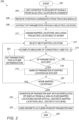
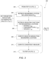
- Figs. 2 and 3 are flowcharts 200 and 300, respectively, that schematically illustrate an automated process for identifying and removing outliers from an EP map, in accordance with an exemplary embodiment of the invention.
- Flowchart 200 illustrates the overall process for acquiring and extracting EP parameters and identifying and removing the outliers from an EP parameter map
- flowchart 300 illustrates the computation of a measure of consistency that is used in identifying outliers.
- the process is described here, for the sake of concreteness and clarity, with reference to the elements of apparatus 20 ( Fig. 1 ).
- the principles of this method may be applied, mutatis mutandis, in other system configurations, including configurations in which the EP signals are processed by a remote server, which communicates with the mapping apparatus via a network.
- the process for acquiring and extracting EP parameters and identifying and removing the outliers from an EP parameter map starts at a start step 202.
- the parameters used in a consistency measure step 214 and in a decision step 216 are set. These parameters will be detailed below and in Fig. 3 .
- EP signals are acquired, with reference to Fig. 1 , by processor 41 from heart 26 through electrodes 48 of catheter 40.
- processor 41 receives signals from tracking module 43, and computes the respective location coordinates of electrodes 48.
- processor 41 extracts the respective EP parameters from the acquired signals. For example, processor 41 may compute a local activation time (LAT) for each location by finding the time (relative to a reference time) at which the peak or the sharpest slope occurs in the signal measured at the location. Alternatively or additionally, processor 41 may compute the peak amplitude of the signal at each location and/or any other signal parameter of interest.
- LAT local activation time
- processor 41 assigns the EP parameters extracted at given locations in the heart (discrete EP parameters) to corresponding locations on a 3D map of the chamber of heart 26, based on the position coordinates received in tracking step 206.
- the 3D map is generated, for example, from an image of the heart previously stored in the processor and/or on the position measurements taken in tracking step 206.
- one (or more) of electrodes 48 may not be touching the surface of heart 26 while acquiring EP signals.
- the position coordinates of the specific electrode 48, as received in tracking step 206 do not coincide with the surface of heart 26, and the mapped location is "detached" from the surface.
- the term "mapped location” is used in the following description, for brevity, to denote a location in the heart at which an EP parameter has been extracted. In order to assign such a mapped location to the 3D map of heart 26, the location in the heart is projected onto the closest location on the surface of the heart, and this location in the heart is now assigned to the mapped location and displayed on the EP parameter map.
- catheter 40 with multiple electrodes 48 travels over the surface of the tissue of heart 26, possibly several times, multiple "detached" mapped locations may be projected onto the same location om the surface. In such a case, a median value of the EP parameters projected to the same location is used for that location.
- processor 41 selects a mapped location for determining whether the EP parameter extracted at that location is an outlier, i.e., whether its measure of consistency does or does not satisfy the consistency criterion.
- the mapped location is selected from those locations, including projected locations, that have not yet been processed in consistency measurement step 214.
- processor 41 computes the measure of consistency for the EP parameter extracted at the mapped location selected in selection step 212.
- the measure of consistency may be proportional to the difference between the EP parameter at the given location and a weighted median of the respective EP parameters at a set of neighboring locations, as detailed in Fig. 3 .
- a large measure of consistency indicates that the EP parameter at the given location is not consistent with its neighbors, and vice versa.
- the measure of consistency may be defined such that the value is large when the EP parameter at a given location is consistent with its neighbors, and small when the EP parameters are inconsistent.
- decision step 216 processor 41 evaluates the measure of consistency from step 214 against a predefined consistency criterion.
- the measure of consistency may be compared to a threshold that was defined in parameter setting step 203. Assuming the measure of consistency was defined to increase with the difference between a given location and its neighbors, if the measure of consistency exceeds the threshold, the EP parameter extracted at the selected location does not satisfy the consistency criterion. In this case, the EP parameter is deemed to be an outlier, and the automated process is directed to an outlier marking step 218.
- the difference between the measure of consistency and the threshold is used as the consistency criterion, other criteria may alternatively be used, as noted earlier.
- processor 41 marks the EP parameter extracted at the selected mapped location as an outlier, and the process continues to an additional location step 220.
- the marking may comprise, for instance, processor 41 adding an indicator flag to a list of mapped locations in its memory.
- processor 41 determines whether there still are locations among the mapped locations that have not been processed through consistency measure step 214. If so, the process returns to selection step 212. If there are no more such locations, the process continues to a continuous display revision step 222.
- processor 41 In a map generation step 222, processor 41 generates an EP parameter map of the chamber of heart 26.
- the 3D map of the chamber (from step 210) is overlaid with either or both of the EP parameters extracted at given locations and an interpolated map of the EP parameters, as further described below.
- all mapped locations including those having possibly outlying EP parameters, are displayed. However, only non-outlier mapped locations are utilized for the interpolated map.
- Processor 41 displays the EP parameters extracted at given locations (discrete EP parameters) on the EP parameter map, based on step 210, for example as small, color-coded circles (or some other suitable shapes).
- the color-coding may comprise, for example, showing the lowest value of the EP parameter as a blue color, the highest value as a red color, and intermediate values between the lowest and highest values in the same order as colors in the visible spectrum.
- other color-coding schemes, as well as shading or symbols, as are known in the art may alternatively be used.
- processor 41 computes and displays a spatially continuous map of the EP parameters by interpolating over the non-outlier EP parameters extracted at given locations.
- the continuous map typically uses the same color-coding as used in displaying the discrete EP parameters.
- the display of the EP parameter map on display screen 27 may be controlled by physician 30.
- an outlier removal step 224 the outliers marked in outlier marking step 218 (also denoted as “discrete outliers") are removed from the EP parameter map, so that the map displays only non-outlier EP parameters at their respective locations.
- the revised EP parameter map of the surface of the chamber includes only non-outlier extracted EP parameters and an interpolated map computed only from these EP parameters.
- processor 41 computes a spatially continuous distribution of the electrophysical parameters in the heart chamber by interpolating only the electrophysiological parameters extracted at the locations for which the respective measure of consistency satisfied the consistency criterion.
- the display of the revised EP parameter map (without discrete outliers) on display screen 27 may again be controlled by physician 30.
- the automated process comes to an end in an end step 226.
- flowchart 300 shows details of the computation of the measure of consistency for an EP parameter extracted at a selected mapped location.
- this process is represented as consistency measure step 214.
- the impact of the EP parameters extracted at neighboring locations is taken into account both by defining the neighboring locations, as detailed below in a radius retrieval step 304, and by weighting their impact, as detailed below in a weighting function retrieval step 306 and in an expected EP parameter step 308.
- the process starts in a start step 302, where the selected mapped location from step 212 in Fig. 2 is received.
- radius retrieval step 304 an inclusion radius R incl for defining neighboring locations is retrieved from parameter step 203 in Fig. 2 .
- a sphere is defined with the selected mapped location as its center and R incl as its radius. All locations inside this sphere are defined as "neighboring locations,” and will be included in determining whether the selected location is an outlier.
- processor 41 retrieves the weighting function (detailed further below) from step 203.
- processor 41 computes a weighted median of the EP parameters extracted at the neighboring locations (locations within radius R incl ), by applying the appropriate weight, as indicated by the weighting function, to each of the EP parameter values.
- weighted median is used in the present description and in the claims in its conventional sense in the statistical arts.
- the weighted median is equal to the simple median of ⁇ x 1 (L 1 ), x 2 (L 2 ), ..., x n (L n ) ⁇ .
- Processor 41 uses the weighted median in a consistency measurement step 310 to compute the measure of consistency as the difference between the EP parameter extracted at the selected mapped location and the weighted median of the EP parameters extracted at the neighboring locations.
- the process in flowchart 300 ends in an end step 312, passing the consistency measure to step 216 in Fig. 2 .
- Any suitable weighting function or combination of functions may be chosen at retrieval step 306.
- the examples shown in Fig. 3 include a distance weighting function f dist , a confidence weighting function f conf , and a variance weighting function f var , which are retrieved from parameter step 203.
- processor 41 uses the distance weighting function f dist to compute the weights so as to take into account the influence of the distance of a neighboring location from the selected location on the weighted median.
- processor 41 computes the weights based on a confidence level of the EP parameter extracted at a neighboring location.
- the confidence level at a neighboring location is influenced, inter alia, by the number of times an EP signal is acquired at a given location due to repeated measurements by an electrode 48.
- an EP parameter extracted in a neighboring location from a signal sampled four times has four times the confidence level of an EP parameter extracted in another neighboring location from a signal sampled only once.
- measures of confidence may be used, such as the location stability, pressure, or impedance measured during signal acquisition at each of the neighboring locations.
- variance weighting function f var processor 41 computes the weights due to a variance between multiple EP parameters extracted at neighboring locations, when these locations are projected to the same location on the surface of heart 26, as described in step 210 in Fig. 2 .
- the variance weighting function f var may be further modified to take into consideration the number of mapped locations projected to the same location. For example, were two locations to exhibit the same variance but a contribution from a dissimilar number of projected locations, the location with a higher number of projected locations would have a higher weight in the computation of weighted median.
- weighting functions either continuous or discrete, may be used.
- the relative impacts of the three weighting functions of distance, confidence, and variance may be selected.
- only one of the weighting functions, or alternatively any combination of the weighting functions, may be included in the computation of an outlier by suitably combining the three weighting functions f dist , f conf , and f var to a composite weighting function f composite .
- the weighting functions are normalized so that the composite weights over each set of neighboring locations sum to 1.
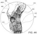
- Figs. 4A and 4B are schematic representations of EP parameter maps 402A and 402B, respectively, illustrating two phases in the process of outlier removal, in accordance with an embodiment of the invention.
- Maps 402A and 402B are both based on a 3D map 408 of the same region of a chamber of heart 26, and with the same continuous map of the values of the EP parameter, as interpolated from the non-outlier EP parameters. The difference between the two maps is that map 402A displays all discrete mapped locations, including outliers, whereas map 402B displays only the non-outlier discrete mapped locations.
- Fig. 4A shows EP parameter map 402A with multiple mapped locations 404 of the EP parameter, for example LAT, overlaid on 3D map 408. Mapped locations 404 are displayed as small circles, with the value of the respective EP parameter shown by color-coding, as described in map generation step 222 in Fig. 2 .
- Fig. 4A also shows an area 406A on map 402A that displays a continuous map of the values of the EP parameter, as interpolated from the non-outlier EP parameters extracted at mapped locations 404. Area 406A is color-coded with the same coding as the EP parameters extracted at mapped locations 404.
- An area 409 on map 402A is displayed as a uniform neutral color, such as grey, signifying that neither mapped locations 404 nor area 406A (the interpolated map) extend to this part of 3D map 408, and consequently this area does not display any values of the EP parameter.
- the EP parameters extracted at mapped locations 410 and 412 have been marked by the automated process to be outliers (step 218 in Fig. 2 ), but they have been left in Fig. 4A in case physician 30 wishes to explore them further. These mapped locations may also at this stage be visually judged to be outliers due to their differences from the EP parameters extracted at the respective neighboring mapped locations. Although the EP parameter extracted at mapped location 414 looks superficially similar to that at mapped location 412, however, it is not an outlier, as several of its immediate neighbors have the same value of the EP parameter.
- Map 402A corresponds to the stage immediately after map generation step 222 in flowchart 200 in Fig. 2 , and its display on display screen 27 may be controlled by physician 30.
- Fig. 4B shows the same areas and locations as Fig. 4A , except that the outliers (at mapped locations 410 and 412) have been removed.
- Area 406B displaying the continuous interpolated EP parameters, is identical to area 406A in Fig. 4A .
- Map 402B corresponds in flowchart 200 to the stage after outlier removal step 224. As above, its display on display screen 27 may be controlled by physician 30.
Landscapes
- Health & Medical Sciences (AREA)
- Life Sciences & Earth Sciences (AREA)
- Engineering & Computer Science (AREA)
- Physics & Mathematics (AREA)
- Public Health (AREA)
- Medical Informatics (AREA)
- Veterinary Medicine (AREA)
- General Health & Medical Sciences (AREA)
- Animal Behavior & Ethology (AREA)
- Biophysics (AREA)
- Pathology (AREA)
- Biomedical Technology (AREA)
- Heart & Thoracic Surgery (AREA)
- Surgery (AREA)
- Molecular Biology (AREA)
- Cardiology (AREA)
- Physiology (AREA)
- General Physics & Mathematics (AREA)
- Theoretical Computer Science (AREA)
- Psychiatry (AREA)
- Computer Vision & Pattern Recognition (AREA)
- Artificial Intelligence (AREA)
- Signal Processing (AREA)
- Measurement And Recording Of Electrical Phenomena And Electrical Characteristics Of The Living Body (AREA)
Claims (11)
- Appareil médical (20), comprenant :une sonde configurée pour être insérée dans le corps d'un patient et comprenant une ou plusieurs électrodes (48) configurées pour entrer en contact avec les tissus d'une région du corps ;un écran d'affichage (27) ;un système de suivi de la position configuré pour acquérir des coordonnées de position de la ou des électrodes dans le corps ; etun processeur (41) configuré pouracquérir des signaux électrophysiologiques respectifs à partir de la ou des électrodes alors que la ou les électrodes sont en contact avec de multiples emplacements de la région ;extraire des paramètres électrophysiologiques respectifs des signaux électrophysiologiques ;calculer une mesure respective de la cohérence des paramètres électrophysiologiques respectifs à chacun des emplacements par rapport à une médiane pondérée des paramètres électrophysiologiques extraits aux emplacements voisins ; etrendre à l'écran d'affichage, en réponse aux coordonnées de position, une carte (408) du tissu tout en superposant sur la carte une indication visuelle des paramètres électrophysiologiques extraits pour lesquels la mesure de cohérence respective satisfait à un critère de cohérence prédéfini, et en omettant automatiquement de la carte les paramètres électrophysiologiques pour lesquels la mesure de cohérence respective n'a pas satisfait au critère de cohérence prédéfini.
- Appareil médical selon la revendication 1, pour tout emplacement donné, les emplacements voisins étant sélectionnés de telle sorte que les distances respectives de l'emplacement donné aux emplacements voisins sont comprises dans un rayon prédéfini.
- Appareil médical selon la revendication 1, le processeur étant configuré pour calculer la mesure de cohérence respective pour tout emplacement donné en calculant une différence entre un paramètre électrophysiologique extrait à l'emplacement donné et la médiane pondérée des paramètres électrophysiologiques extraits aux emplacements voisins.
- Appareil médical selon la revendication 3, le critère de cohérence prédéfini étant satisfait lorsque la différence calculée ne dépasse pas un seuil prédéfini.
- Appareil médical selon la revendication 1, le processeur étant configuré pour calculer la médiane pondérée en appliquant des poids aux paramètres électrophysiologiques extraits aux emplacements voisins à l'aide d'une fonction de pondération sélectionnée dans une liste de fonctions de pondération comprenant une fonction de pondération de distance, une fonction de pondération de confiance et une fonction de pondération de variance.
- Appareil médical selon la revendication 5, pour tout emplacement donné, la fonction de pondération de la distance appliquant un poids qui diminue avec l'augmentation de la distance entre l'emplacement donné et les emplacements voisins.
- Appareil médical selon la revendication 5, la fonction de pondération de confiance étant calculée pour chaque emplacement voisin donné en fonction du nombre de fois qu'un signal électrophysiologique a été acquis à l'emplacement voisin donné.
- Appareil médical selon la revendication 5, la fonction de pondération de la variance appliquant un poids qui diminue avec l'augmentation de la variance des paramètres électrophysiologiques projetés à l'emplacement voisin.
- Appareil médical selon la revendication 1, le processeur étant configuré pour calculer et rendre à l'écran d'affichage une distribution spatialement continue des paramètres électrophysiologiques dans la région en interpolant uniquement les paramètres électrophysiologiques extraits aux emplacements pour lesquels la mesure de cohérence respective a satisfait le critère de cohérence prédéfini.
- Appareil médical selon la revendication 1, les paramètres électrophysiologiques comprenant un temps d'activation local (LAT) dans un cœur (26) du patient.
- Appareil médical selon la revendication 1, les paramètres électrophysiologiques comprenant une tension électrophysiologique dans un tissu du patient.
Applications Claiming Priority (1)
| Application Number | Priority Date | Filing Date | Title |
|---|---|---|---|
| US17/036,227 US12156736B2 (en) | 2020-09-29 | 2020-09-29 | Real time removal of EP parameter outliers from visual map |
Publications (3)
| Publication Number | Publication Date |
|---|---|
| EP3973876A1 EP3973876A1 (fr) | 2022-03-30 |
| EP3973876C0 EP3973876C0 (fr) | 2024-01-10 |
| EP3973876B1 true EP3973876B1 (fr) | 2024-01-10 |
Family
ID=78211796
Family Applications (1)
| Application Number | Title | Priority Date | Filing Date |
|---|---|---|---|
| EP21199564.2A Active EP3973876B1 (fr) | 2020-09-29 | 2021-09-28 | Élimination en temps réel des valeurs aberrantes de paramètres ep à partir d'une carte visuelle |
Country Status (5)
| Country | Link |
|---|---|
| US (1) | US12156736B2 (fr) |
| EP (1) | EP3973876B1 (fr) |
| JP (1) | JP7830062B2 (fr) |
| CN (1) | CN114305448A (fr) |
| IL (1) | IL286525B2 (fr) |
Families Citing this family (4)
| Publication number | Priority date | Publication date | Assignee | Title |
|---|---|---|---|---|
| US12023168B2 (en) * | 2021-04-21 | 2024-07-02 | Biosense Webster (Israel) Ltd. | Electrophysiological (EP) map coloration by considering outliers |
| US20250025089A1 (en) * | 2023-07-21 | 2025-01-23 | Biosense Webster (Israel) Ltd. | Estimation and visualization of electroanatomical (ea) analysis quality of an ea map |
| US20250241715A1 (en) | 2024-01-29 | 2025-07-31 | Biosense Webster (Israel) Ltd. | Gui to display locations of early and late local activation times (lat) in lat map and correct the map |
| US12496138B2 (en) | 2024-01-31 | 2025-12-16 | Biosense Webster (Israel) Ltd. | Automated tool for identifying and correcting tenting artifacts in anatomical mapping |
Family Cites Families (23)
| Publication number | Priority date | Publication date | Assignee | Title |
|---|---|---|---|---|
| US5391199A (en) | 1993-07-20 | 1995-02-21 | Biosense, Inc. | Apparatus and method for treating cardiac arrhythmias |
| JP3708121B2 (ja) | 1994-08-19 | 2005-10-19 | バイオセンス・インコーポレイテッド | 医療用機器の診断及び取扱いならびに映像システム |
| US6690963B2 (en) | 1995-01-24 | 2004-02-10 | Biosense, Inc. | System for determining the location and orientation of an invasive medical instrument |
| IL125761A (en) | 1996-02-15 | 2005-05-17 | Biosense Inc | Independently positionable transducers for location system |
| IL125757A (en) | 1996-02-15 | 2003-09-17 | Biosense Inc | Medical procedures and apparatus using intrabody probes |
| US6239724B1 (en) | 1997-12-30 | 2001-05-29 | Remon Medical Technologies, Ltd. | System and method for telemetrically providing intrabody spatial position |
| US7590441B2 (en) * | 1999-03-11 | 2009-09-15 | Biosense, Inc. | Invasive medical device with position sensing and display |
| US6484118B1 (en) | 2000-07-20 | 2002-11-19 | Biosense, Inc. | Electromagnetic position single axis system |
| US7729742B2 (en) | 2001-12-21 | 2010-06-01 | Biosense, Inc. | Wireless position sensor |
| US20040068178A1 (en) | 2002-09-17 | 2004-04-08 | Assaf Govari | High-gradient recursive locating system |
| US20080247465A1 (en) * | 2007-04-05 | 2008-10-09 | Jun Xin | Method and System for Mapping Motion Vectors between Different Size Blocks |
| JP4960162B2 (ja) * | 2007-07-17 | 2012-06-27 | 株式会社東芝 | 超音波診断装置 |
| JP5911726B2 (ja) | 2008-11-10 | 2016-04-27 | カーディオインサイト テクノロジーズ インコーポレイテッド | 電気生理学データの視覚化 |
| JP5956463B2 (ja) | 2010-12-30 | 2016-07-27 | セント・ジュード・メディカル・エイトリアル・フィブリレーション・ディヴィジョン・インコーポレーテッド | 身体組織から電子生理学的データを分析しマッピングするシステム、電子生理学的データを分析するシステムの作動方法及び心臓組織から測定されるデータを分析するカテーテルシステム |
| US8428700B2 (en) * | 2011-01-13 | 2013-04-23 | Rhythmia Medical, Inc. | Electroanatomical mapping |
| US8812091B1 (en) | 2013-03-15 | 2014-08-19 | Apn Health, Llc | Multi-channel cardiac measurements |
| JP6200590B2 (ja) | 2013-08-20 | 2017-09-20 | セント・ジュード・メディカル・エイトリアル・フィブリレーション・ディヴィジョン・インコーポレーテッド | 電気生理学的マップを生成するためのシステムおよび方法 |
| US9949657B2 (en) | 2015-12-07 | 2018-04-24 | Biosense Webster (Israel) Ltd. | Displaying multiple-activation areas on an electroanatomical map |
| WO2018013341A1 (fr) * | 2016-07-15 | 2018-01-18 | St. Jude Medical, Cardiology Division, Inc. | Procédés et systèmes de génération d'images lissées d'un dispositif médical allongé |
| US10219716B2 (en) * | 2017-06-01 | 2019-03-05 | Biosense Webster (Israel) Ltd. | Using a piecewise-linear model of a catheter arm to identify contact with tissue |
| US10398348B2 (en) | 2017-10-19 | 2019-09-03 | Biosense Webster (Israel) Ltd. | Baseline impedance maps for tissue proximity indications |
| US11350867B2 (en) | 2018-04-27 | 2022-06-07 | Duke University | Small-scale time delay and single-shot conduction velocity analysis and mapping for cardiac electrophysiology |
| US11969254B2 (en) | 2019-03-12 | 2024-04-30 | St. Jude Medical, Cardiology Division, Inc. | System and method for cardiac mapping |
-
2020
- 2020-09-29 US US17/036,227 patent/US12156736B2/en active Active
-
2021
- 2021-09-19 IL IL286525A patent/IL286525B2/en unknown
- 2021-09-28 JP JP2021157595A patent/JP7830062B2/ja active Active
- 2021-09-28 EP EP21199564.2A patent/EP3973876B1/fr active Active
- 2021-09-29 CN CN202111149251.2A patent/CN114305448A/zh active Pending
Also Published As
| Publication number | Publication date |
|---|---|
| IL286525B1 (en) | 2024-05-01 |
| EP3973876A1 (fr) | 2022-03-30 |
| IL286525B2 (en) | 2024-09-01 |
| CN114305448A (zh) | 2022-04-12 |
| US20220095942A1 (en) | 2022-03-31 |
| JP7830062B2 (ja) | 2026-03-16 |
| EP3973876C0 (fr) | 2024-01-10 |
| JP2022056404A (ja) | 2022-04-08 |
| US12156736B2 (en) | 2024-12-03 |
| IL286525A (en) | 2022-04-01 |
Similar Documents
| Publication | Publication Date | Title |
|---|---|---|
| EP3834730B1 (fr) | Présentation graphique automatique de paramètres électrophysiologiques | |
| CN112998721B (zh) | 电生理参数的双选图形呈现 | |
| EP3973876A1 (fr) | Élimination en temps réel des valeurs aberrantes de paramètres ep à partir d'une carte visuelle | |
| US11918383B2 (en) | Visualizing performance of catheter electrodes | |
| EP4062833A1 (fr) | Visualisation de paramètres multiples superposés sur une carte anatomique | |
| EP3628256A1 (fr) | Système de transmission de radiofréquence (rf) pour détecter la proximité de tissus | |
| EP4005467B1 (fr) | Guidage d'acquisition de cartographie électro-anatomique | |
| EP4321091A1 (fr) | Visualisation et regroupement de multiples électrodes d'un cathéter à haute définition projeté sur une surface de tissu | |
| EP4494561A1 (fr) | Estimation et visualisation de la qualité d'analyse électroanatomique (ea) d'une carte d'ea |
Legal Events
| Date | Code | Title | Description |
|---|---|---|---|
| PUAI | Public reference made under article 153(3) epc to a published international application that has entered the european phase |
Free format text: ORIGINAL CODE: 0009012 |
|
| STAA | Information on the status of an ep patent application or granted ep patent |
Free format text: STATUS: THE APPLICATION HAS BEEN PUBLISHED |
|
| AK | Designated contracting states |
Kind code of ref document: A1 Designated state(s): AL AT BE BG CH CY CZ DE DK EE ES FI FR GB GR HR HU IE IS IT LI LT LU LV MC MK MT NL NO PL PT RO RS SE SI SK SM TR |
|
| RAP3 | Party data changed (applicant data changed or rights of an application transferred) |
Owner name: BIOSENSE WEBSTER (ISRAEL) LTD. |
|
| STAA | Information on the status of an ep patent application or granted ep patent |
Free format text: STATUS: REQUEST FOR EXAMINATION WAS MADE |
|
| 17P | Request for examination filed |
Effective date: 20220617 |
|
| RBV | Designated contracting states (corrected) |
Designated state(s): AL AT BE BG CH CY CZ DE DK EE ES FI FR GB GR HR HU IE IS IT LI LT LU LV MC MK MT NL NO PL PT RO RS SE SI SK SM TR |
|
| GRAP | Despatch of communication of intention to grant a patent |
Free format text: ORIGINAL CODE: EPIDOSNIGR1 |
|
| STAA | Information on the status of an ep patent application or granted ep patent |
Free format text: STATUS: GRANT OF PATENT IS INTENDED |
|
| INTG | Intention to grant announced |
Effective date: 20230816 |
|
| GRAS | Grant fee paid |
Free format text: ORIGINAL CODE: EPIDOSNIGR3 |
|
| GRAA | (expected) grant |
Free format text: ORIGINAL CODE: 0009210 |
|
| STAA | Information on the status of an ep patent application or granted ep patent |
Free format text: STATUS: THE PATENT HAS BEEN GRANTED |
|
| AK | Designated contracting states |
Kind code of ref document: B1 Designated state(s): AL AT BE BG CH CY CZ DE DK EE ES FI FR GB GR HR HU IE IS IT LI LT LU LV MC MK MT NL NO PL PT RO RS SE SI SK SM TR |
|
| REG | Reference to a national code |
Ref country code: GB Ref legal event code: FG4D |
|
| REG | Reference to a national code |
Ref country code: CH Ref legal event code: EP |
|
| REG | Reference to a national code |
Ref country code: DE Ref legal event code: R096 Ref document number: 602021008485 Country of ref document: DE |
|
| REG | Reference to a national code |
Ref country code: IE Ref legal event code: FG4D |
|
| U01 | Request for unitary effect filed |
Effective date: 20240131 |
|
| U07 | Unitary effect registered |
Designated state(s): AT BE BG DE DK EE FI FR IT LT LU LV MT NL PT SE SI Effective date: 20240208 |
|
| PG25 | Lapsed in a contracting state [announced via postgrant information from national office to epo] |
Ref country code: IS Free format text: LAPSE BECAUSE OF FAILURE TO SUBMIT A TRANSLATION OF THE DESCRIPTION OR TO PAY THE FEE WITHIN THE PRESCRIBED TIME-LIMIT Effective date: 20240510 |
|
| PG25 | Lapsed in a contracting state [announced via postgrant information from national office to epo] |
Ref country code: GR Free format text: LAPSE BECAUSE OF FAILURE TO SUBMIT A TRANSLATION OF THE DESCRIPTION OR TO PAY THE FEE WITHIN THE PRESCRIBED TIME-LIMIT Effective date: 20240411 |
|
| PG25 | Lapsed in a contracting state [announced via postgrant information from national office to epo] |
Ref country code: HR Free format text: LAPSE BECAUSE OF FAILURE TO SUBMIT A TRANSLATION OF THE DESCRIPTION OR TO PAY THE FEE WITHIN THE PRESCRIBED TIME-LIMIT Effective date: 20240110 Ref country code: RS Free format text: LAPSE BECAUSE OF FAILURE TO SUBMIT A TRANSLATION OF THE DESCRIPTION OR TO PAY THE FEE WITHIN THE PRESCRIBED TIME-LIMIT Effective date: 20240410 |
|
| PG25 | Lapsed in a contracting state [announced via postgrant information from national office to epo] |
Ref country code: ES Free format text: LAPSE BECAUSE OF FAILURE TO SUBMIT A TRANSLATION OF THE DESCRIPTION OR TO PAY THE FEE WITHIN THE PRESCRIBED TIME-LIMIT Effective date: 20240110 |
|
| PG25 | Lapsed in a contracting state [announced via postgrant information from national office to epo] |
Ref country code: RS Free format text: LAPSE BECAUSE OF FAILURE TO SUBMIT A TRANSLATION OF THE DESCRIPTION OR TO PAY THE FEE WITHIN THE PRESCRIBED TIME-LIMIT Effective date: 20240410 Ref country code: NO Free format text: LAPSE BECAUSE OF FAILURE TO SUBMIT A TRANSLATION OF THE DESCRIPTION OR TO PAY THE FEE WITHIN THE PRESCRIBED TIME-LIMIT Effective date: 20240410 Ref country code: IS Free format text: LAPSE BECAUSE OF FAILURE TO SUBMIT A TRANSLATION OF THE DESCRIPTION OR TO PAY THE FEE WITHIN THE PRESCRIBED TIME-LIMIT Effective date: 20240510 Ref country code: HR Free format text: LAPSE BECAUSE OF FAILURE TO SUBMIT A TRANSLATION OF THE DESCRIPTION OR TO PAY THE FEE WITHIN THE PRESCRIBED TIME-LIMIT Effective date: 20240110 Ref country code: GR Free format text: LAPSE BECAUSE OF FAILURE TO SUBMIT A TRANSLATION OF THE DESCRIPTION OR TO PAY THE FEE WITHIN THE PRESCRIBED TIME-LIMIT Effective date: 20240411 Ref country code: ES Free format text: LAPSE BECAUSE OF FAILURE TO SUBMIT A TRANSLATION OF THE DESCRIPTION OR TO PAY THE FEE WITHIN THE PRESCRIBED TIME-LIMIT Effective date: 20240110 |
|
| PG25 | Lapsed in a contracting state [announced via postgrant information from national office to epo] |
Ref country code: PL Free format text: LAPSE BECAUSE OF FAILURE TO SUBMIT A TRANSLATION OF THE DESCRIPTION OR TO PAY THE FEE WITHIN THE PRESCRIBED TIME-LIMIT Effective date: 20240110 |
|
| PG25 | Lapsed in a contracting state [announced via postgrant information from national office to epo] |
Ref country code: PL Free format text: LAPSE BECAUSE OF FAILURE TO SUBMIT A TRANSLATION OF THE DESCRIPTION OR TO PAY THE FEE WITHIN THE PRESCRIBED TIME-LIMIT Effective date: 20240110 |
|
| U20 | Renewal fee for the european patent with unitary effect paid |
Year of fee payment: 4 Effective date: 20240807 |
|
| REG | Reference to a national code |
Ref country code: DE Ref legal event code: R097 Ref document number: 602021008485 Country of ref document: DE |
|
| PG25 | Lapsed in a contracting state [announced via postgrant information from national office to epo] |
Ref country code: SM Free format text: LAPSE BECAUSE OF FAILURE TO SUBMIT A TRANSLATION OF THE DESCRIPTION OR TO PAY THE FEE WITHIN THE PRESCRIBED TIME-LIMIT Effective date: 20240110 |
|
| PG25 | Lapsed in a contracting state [announced via postgrant information from national office to epo] |
Ref country code: CZ Free format text: LAPSE BECAUSE OF FAILURE TO SUBMIT A TRANSLATION OF THE DESCRIPTION OR TO PAY THE FEE WITHIN THE PRESCRIBED TIME-LIMIT Effective date: 20240110 |
|
| PG25 | Lapsed in a contracting state [announced via postgrant information from national office to epo] |
Ref country code: SK Free format text: LAPSE BECAUSE OF FAILURE TO SUBMIT A TRANSLATION OF THE DESCRIPTION OR TO PAY THE FEE WITHIN THE PRESCRIBED TIME-LIMIT Effective date: 20240110 |
|
| PG25 | Lapsed in a contracting state [announced via postgrant information from national office to epo] |
Ref country code: SM Free format text: LAPSE BECAUSE OF FAILURE TO SUBMIT A TRANSLATION OF THE DESCRIPTION OR TO PAY THE FEE WITHIN THE PRESCRIBED TIME-LIMIT Effective date: 20240110 Ref country code: SK Free format text: LAPSE BECAUSE OF FAILURE TO SUBMIT A TRANSLATION OF THE DESCRIPTION OR TO PAY THE FEE WITHIN THE PRESCRIBED TIME-LIMIT Effective date: 20240110 Ref country code: RO Free format text: LAPSE BECAUSE OF FAILURE TO SUBMIT A TRANSLATION OF THE DESCRIPTION OR TO PAY THE FEE WITHIN THE PRESCRIBED TIME-LIMIT Effective date: 20240110 Ref country code: CZ Free format text: LAPSE BECAUSE OF FAILURE TO SUBMIT A TRANSLATION OF THE DESCRIPTION OR TO PAY THE FEE WITHIN THE PRESCRIBED TIME-LIMIT Effective date: 20240110 |
|
| PLBE | No opposition filed within time limit |
Free format text: ORIGINAL CODE: 0009261 |
|
| STAA | Information on the status of an ep patent application or granted ep patent |
Free format text: STATUS: NO OPPOSITION FILED WITHIN TIME LIMIT |
|
| 26N | No opposition filed |
Effective date: 20241011 |
|
| PG25 | Lapsed in a contracting state [announced via postgrant information from national office to epo] |
Ref country code: MC Free format text: LAPSE BECAUSE OF FAILURE TO SUBMIT A TRANSLATION OF THE DESCRIPTION OR TO PAY THE FEE WITHIN THE PRESCRIBED TIME-LIMIT Effective date: 20240110 |
|
| REG | Reference to a national code |
Ref country code: CH Ref legal event code: PL |
|
| PG25 | Lapsed in a contracting state [announced via postgrant information from national office to epo] |
Ref country code: CH Free format text: LAPSE BECAUSE OF NON-PAYMENT OF DUE FEES Effective date: 20240930 |
|
| PG25 | Lapsed in a contracting state [announced via postgrant information from national office to epo] |
Ref country code: IE Free format text: LAPSE BECAUSE OF NON-PAYMENT OF DUE FEES Effective date: 20240928 |
|
| U20 | Renewal fee for the european patent with unitary effect paid |
Year of fee payment: 5 Effective date: 20250807 |
|
| PGFP | Annual fee paid to national office [announced via postgrant information from national office to epo] |
Ref country code: GB Payment date: 20250807 Year of fee payment: 5 |
|
| PG25 | Lapsed in a contracting state [announced via postgrant information from national office to epo] |
Ref country code: CY Free format text: LAPSE BECAUSE OF FAILURE TO SUBMIT A TRANSLATION OF THE DESCRIPTION OR TO PAY THE FEE WITHIN THE PRESCRIBED TIME-LIMIT; INVALID AB INITIO Effective date: 20210928 |
|
| PG25 | Lapsed in a contracting state [announced via postgrant information from national office to epo] |
Ref country code: HU Free format text: LAPSE BECAUSE OF FAILURE TO SUBMIT A TRANSLATION OF THE DESCRIPTION OR TO PAY THE FEE WITHIN THE PRESCRIBED TIME-LIMIT; INVALID AB INITIO Effective date: 20210928 |