EP3974033A1 - Feuerbeständiges element, feuerschutzstruktur und verfahren zur installation einer brandschutzstruktur - Google Patents
Feuerbeständiges element, feuerschutzstruktur und verfahren zur installation einer brandschutzstruktur Download PDFInfo
- Publication number
- EP3974033A1 EP3974033A1 EP20809057.1A EP20809057A EP3974033A1 EP 3974033 A1 EP3974033 A1 EP 3974033A1 EP 20809057 A EP20809057 A EP 20809057A EP 3974033 A1 EP3974033 A1 EP 3974033A1
- Authority
- EP
- European Patent Office
- Prior art keywords
- cylindrical body
- tongue
- resistant member
- fire resistant
- shaped pieces
- Prior art date
- Legal status (The legal status is an assumption and is not a legal conclusion. Google has not performed a legal analysis and makes no representation as to the accuracy of the status listed.)
- Withdrawn
Links
- 230000009970 fire resistant effect Effects 0.000 title claims abstract description 107
- 238000000034 method Methods 0.000 title claims description 9
- 239000006260 foam Substances 0.000 claims abstract description 147
- 229910052751 metal Inorganic materials 0.000 claims abstract description 41
- 239000002184 metal Substances 0.000 claims abstract description 41
- 239000000463 material Substances 0.000 claims abstract description 29
- 238000000638 solvent extraction Methods 0.000 claims description 31
- 229920005989 resin Polymers 0.000 abstract description 5
- 239000011347 resin Substances 0.000 abstract description 5
- JOYRKODLDBILNP-UHFFFAOYSA-N Ethyl urethane Chemical compound CCOC(N)=O JOYRKODLDBILNP-UHFFFAOYSA-N 0.000 abstract description 3
- RNFJDJUURJAICM-UHFFFAOYSA-N 2,2,4,4,6,6-hexaphenoxy-1,3,5-triaza-2$l^{5},4$l^{5},6$l^{5}-triphosphacyclohexa-1,3,5-triene Chemical compound N=1P(OC=2C=CC=CC=2)(OC=2C=CC=CC=2)=NP(OC=2C=CC=CC=2)(OC=2C=CC=CC=2)=NP=1(OC=1C=CC=CC=1)OC1=CC=CC=C1 RNFJDJUURJAICM-UHFFFAOYSA-N 0.000 abstract description 2
- 239000003063 flame retardant Substances 0.000 abstract description 2
- 230000000694 effects Effects 0.000 description 11
- 150000001336 alkenes Chemical class 0.000 description 7
- JRZJOMJEPLMPRA-UHFFFAOYSA-N olefin Natural products CCCCCCCC=C JRZJOMJEPLMPRA-UHFFFAOYSA-N 0.000 description 7
- 229920001577 copolymer Polymers 0.000 description 6
- 238000003780 insertion Methods 0.000 description 6
- 230000037431 insertion Effects 0.000 description 6
- 238000005452 bending Methods 0.000 description 5
- 239000004570 mortar (masonry) Substances 0.000 description 4
- 229920005672 polyolefin resin Polymers 0.000 description 4
- 229920000089 Cyclic olefin copolymer Polymers 0.000 description 3
- 239000000853 adhesive Substances 0.000 description 3
- 229920001684 low density polyethylene Polymers 0.000 description 3
- 239000004702 low-density polyethylene Substances 0.000 description 3
- 239000005038 ethylene vinyl acetate Substances 0.000 description 2
- 229920001519 homopolymer Polymers 0.000 description 2
- 238000009434 installation Methods 0.000 description 2
- 238000005192 partition Methods 0.000 description 2
- 229920001200 poly(ethylene-vinyl acetate) Polymers 0.000 description 2
- 238000005096 rolling process Methods 0.000 description 2
- -1 vinyl compound Chemical class 0.000 description 2
- 238000004804 winding Methods 0.000 description 2
- OKTJSMMVPCPJKN-UHFFFAOYSA-N Carbon Chemical compound [C] OKTJSMMVPCPJKN-UHFFFAOYSA-N 0.000 description 1
- 229910052782 aluminium Inorganic materials 0.000 description 1
- XAGFODPZIPBFFR-UHFFFAOYSA-N aluminium Chemical compound [Al] XAGFODPZIPBFFR-UHFFFAOYSA-N 0.000 description 1
- 239000011203 carbon fibre reinforced carbon Substances 0.000 description 1
- 150000001875 compounds Chemical class 0.000 description 1
- 239000006185 dispersion Substances 0.000 description 1
- 229920006242 ethylene acrylic acid copolymer Polymers 0.000 description 1
- 229920006244 ethylene-ethyl acrylate Polymers 0.000 description 1
- 238000001125 extrusion Methods 0.000 description 1
- 229910002804 graphite Inorganic materials 0.000 description 1
- 239000010439 graphite Substances 0.000 description 1
- 229920001903 high density polyethylene Polymers 0.000 description 1
- 239000004700 high-density polyethylene Substances 0.000 description 1
- 238000005304 joining Methods 0.000 description 1
- 238000004519 manufacturing process Methods 0.000 description 1
- 238000012986 modification Methods 0.000 description 1
- 230000004048 modification Effects 0.000 description 1
- 229920000098 polyolefin Polymers 0.000 description 1
- 230000002265 prevention Effects 0.000 description 1
- 230000009528 severe injury Effects 0.000 description 1
- 238000009958 sewing Methods 0.000 description 1
- 229910001220 stainless steel Inorganic materials 0.000 description 1
- 239000010935 stainless steel Substances 0.000 description 1
- 229920002554 vinyl polymer Polymers 0.000 description 1
Images







Classifications
-
- H—ELECTRICITY
- H02—GENERATION; CONVERSION OR DISTRIBUTION OF ELECTRIC POWER
- H02G—INSTALLATION OF ELECTRIC CABLES OR LINES, OR OF COMBINED OPTICAL AND ELECTRIC CABLES OR LINES
- H02G3/00—Installations of electric cables or lines or protective tubing therefor in or on buildings, equivalent structures or vehicles
- H02G3/22—Installations of cables or lines through walls, floors or ceilings, e.g. into buildings
-
- A—HUMAN NECESSITIES
- A62—LIFE-SAVING; FIRE-FIGHTING
- A62C—FIRE-FIGHTING
- A62C2/00—Fire prevention or containment
- A62C2/06—Physical fire-barriers
- A62C2/065—Physical fire-barriers having as the main closure device materials, whose characteristics undergo an irreversible change under high temperatures, e.g. intumescent
-
- A—HUMAN NECESSITIES
- A62—LIFE-SAVING; FIRE-FIGHTING
- A62C—FIRE-FIGHTING
- A62C3/00—Fire prevention, containment or extinguishing specially adapted for particular objects or places
- A62C3/16—Fire prevention, containment or extinguishing specially adapted for particular objects or places in electrical installations, e.g. cableways
-
- F—MECHANICAL ENGINEERING; LIGHTING; HEATING; WEAPONS; BLASTING
- F16—ENGINEERING ELEMENTS AND UNITS; GENERAL MEASURES FOR PRODUCING AND MAINTAINING EFFECTIVE FUNCTIONING OF MACHINES OR INSTALLATIONS; THERMAL INSULATION IN GENERAL
- F16L—PIPES; JOINTS OR FITTINGS FOR PIPES; SUPPORTS FOR PIPES, CABLES OR PROTECTIVE TUBING; MEANS FOR THERMAL INSULATION IN GENERAL
- F16L5/00—Devices for use where pipes, cables or protective tubing pass through walls or partitions
- F16L5/02—Sealing
- F16L5/04—Sealing to form a firebreak device
-
- H—ELECTRICITY
- H02—GENERATION; CONVERSION OR DISTRIBUTION OF ELECTRIC POWER
- H02G—INSTALLATION OF ELECTRIC CABLES OR LINES, OR OF COMBINED OPTICAL AND ELECTRIC CABLES OR LINES
- H02G3/00—Installations of electric cables or lines or protective tubing therefor in or on buildings, equivalent structures or vehicles
- H02G3/02—Details
- H02G3/04—Protective tubing or conduits, e.g. cable ladders or cable troughs
- H02G3/0406—Details thereof
- H02G3/0412—Heat or fire protective means
Definitions
- the present invention relates to a fires resistant member that enables a through portion, such as a pipe or a cable passing through a partitioning section, to have fire resistant ability.
- Patent Document 1 As a fire preventing structure for such long bodies that penetrate partitioning sections, there is a method in which thermally expandable putty or mortar is filled into gaps between the long body and a through hole (Patent Document 1, for example).
- a fire resistant member including a substantially cylindrical main body, a thermally expandable member provided on an inner surface of the main body, and a foam body provided on an inner periphery surface of the main body and the thermally expandable member, in which convex-concave shapes are formed on an inner surface side of the foam body (Patent Document 2, for example).
- Patent Document 2 excels in installation and can provide high fire resistant performance for a through hole with a diameter that is less than a predetermined value
- the structure includes many components such as the main body, the thermally expandable member, and the foam body. This leads to an increase in cost and weight.
- a fire resistant member that is applicable to a larger through hole and has a simpler structure has been desired.
- the present invention was made in view of such problems. Its object is to provide a fire resistant member that has a simple structure and can be applied to a large through hole, and the like.
- a first aspect of the invention is a fire resistant member that is inserted into a through hole in a partitioning section.
- the fire resistant member includes a first foam body in which a thermal expansion material is dispersed.
- the first foam body is rolled up to form a cylindrical body, and a plurality of first tongue-shaped pieces pointing toward a center are disposed in a circumferential direction of the cylindrical body at a plurality of positions in an axial direction of the cylindrical body.
- a plurality of incisions may be formed at both end parts of the cylindrical body forming the first tongue-shaped pieces that are bent toward the center at both end parts of the cylindrical body.
- the first tongue-shaped pieces may be fixed to an inner surface of the cylindrical body. That is, forming positions of the first tongue-shaped pieces are not limited to the both end parts of the cylindrical body. Also, the forming positions of the first tongue-shaped pieces in the circumferential direction may not be on the same plane.
- forming positions in the circumferential direction of the first tongue-shaped pieces on the end part at a part of the axial direction of the cylindrical body and forming positions in the circumferential direction of the first tongue-shaped pieces at another part of the axial direction of the cylindrical body are shifted from each other.
- the cylindrical body may be formed with a second foam body, including the dispersed thermal expansion material, that is wound around an outer periphery part of the first foam body, and a plurality of incisions may be formed at one end part of the second foam body forming second tongue-shaped pieces.
- the second tongue-shaped pieces may be bent outward at a side of the one end part of the cylindrical body forming a flange portion.
- the second tongue-shaped pieces may be formed between the first tongue-shaped pieces at a side of the one end part of the cylindrical body and the second tongue-shaped pieces may be bent outward forming the flange portion.
- a metal tape or a metal plate is preferably wound around the outer periphery part of the cylindrical body.
- a length of the first tongue-shaped piece may be longer than a half of an inner diameter of the cylindrical body.
- a third foam body including the dispersed thermal expansion material may be attached inside the cylindrical body.
- a fire preventing structure with excellent workability can be obtained without using mortar or the like.
- the foam body forming the cylindrical body includes the dispersed thermal expansion material itself, the thermal expansion material can be disposed at a position close to the long body and can be in contact with the long body.
- the thermal expansion material can seal the through hole in a short time.
- the first tongue-shaped pieces that serve as a screen between inside and outside of the partitioning section are disposed at a plurality of positions along the parts through which the long body penetrates, the fire preventing structure can support the long body and shield the view with certainty.
- first tongue-shaped pieces are formed as one body with the cylindrical body. This reduces the number of component pieces and simplifies the structure.
- the first tongue-shaped pieces can be disposed at any desired position of the cylindrical body.
- the forming positions of the first tongue-shaped pieces in the circumferential direction at different positions in the axial direction of the cylindrical body are shifted form each other, and thus gaps between the first tongue-shaped pieces can be shifted, which improves the screen effects.
- winding the second foam body including the dispersed thermal expansion material around the outer periphery part of the first foam body can increase a thickness of the cylindrical body, which can provide a larger amount of expansion and make the space between the inner surface of the through hole and the long body smaller.
- winding the second tongue-shaped pieces on the end part of the second foam body and bending the second tongue-shaped pieces outward to form the flange portion positioning of the axial direction of the cylindrical body against the through hole can be determined.
- the first foam body alone can provide functions for shielding the view and determination of the positioning of the axial direction of the cylindrical body.
- the metal tape or the metal plate being wound around the outer periphery part of the cylindrical body, crushing or deforming of the cylindrical body can be prevented when inserting the cylindrical body into the through hole, and this facilitates insertion of the cylindrical body into the thorough hole.
- the inner surface of the through hole and the cylindrical body can be adhered to each other due to the deformation of the foam body.
- the length of the first tongue-shaped pieces larger than the half of the inner diameter of the cylindrical body enables the first tongue-shaped pieces to be formed slanted to the diameter direction of the cylindrical body when tip ends of the first tongue-shaped pieces are butted to each other.
- the cylindrical body can be in contact with the long body with more certainty and the screen effects can be improved.
- attaching the third foam body including the dispersed thermal expansion material to the inside of the cylindrical body can fill the space between the inner surface of the cylindrical body and the long body.
- a second aspect of the invention is a fire preventing structure including a through hole provided in a partitioning section, a fire resistant member provided in the through hole, and a long body that is inserted into the fire resistant member.
- the fire resistant member includes a first foam body including dispersed thermal expansion material.
- the first foam body forms a cylindrical body.
- a plurality of first tongue-shaped pieces pointing toward a center are formed in a circumferential direction at a plurality of positions in an axial direction of the cylindrical body.
- the long body is in contact with the first tongue-shaped pieces.
- a space may be formed inside the through hole between at least a part of an inner surface of the cylindrical body and the long body.
- a fire preventing structure having a simple structure that is applicable to various sizes of the through hole can be obtained.
- forming the space between the long body and the cylindrical body can make the cylindrical body slide smoothly against the long body.
- the installation to the through hole is easy.
- a third aspect of the invention is a method for installing a fire preventing structure in which a fire resistant member is provided in a through hole formed in a partitioning section.
- the fire resistant member includes a first foam body including dispersed thermal expansion material.
- the first foam body forms a cylindrical body.
- a plurality of first tongue-shaped pieces pointing toward a center are formed in a circumferential direction at a plurality of positions in an axial direction of the cylindrical body.
- a slit is formed along the axial direction of the cylindrical body at a part of the circumferential direction of the cylindrical body.
- the method includes a step of inserting a long body into the through hole, and a step of opening up the slit, installing the fire resistant member on an outer periphery of the long body, and inserting the fire resistant member into the through hole.
- a fire preventing structure that can be used by only being inserted into a through hole without using mortar or the like can be easily obtained.
- the present invention can provide a fire resistant member that has a simple structure and can be applied to a large through hole, and the like.
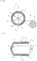
- FIG. 1A is a side view and FIG. 1B is a front view showing a fire resistant member 1 according to the present invention.
- FIG. 2A and FIG. 2B are cross sectional views of the fire resistant member 1: FIG. 2A is a cross sectional view taken along C-C line in FIG. 2B, and FIG. 2B is a cross sectional view taken along A-A line in FIG. 2A .
- the fire resistant member 1 is used being inserted into a thorough hole formed in a partitioning section that partitions spaces such as walls, floors, and ceilings.
- the fire resistant member 1 mainly includes a foam body 13a, which is a first foam body, a metal tape 5, and so on.
- the foam body 13a is a resin foam body and any material, such as a flame-retardant sponge including polyolefin-based resin or urethane-based resin as a base resin, is applicable.
- the polyolefin-based resin in the present invention refers to olefin homopolymers and/or olefin copolymers.
- An olefin homopolymer refers to a copolymer derived from single olefin polymer species.
- Olefin copolymers includes copolymers including olefin as a component in a broad sense, such as a copolymer derived from one species of olefin and another species of olefin, or a copolymer derived from olefin and a compound other than olefin, such as vinyl compound, having a carbon-carbon double bond.
- polyolefin-based resin examples include low-density polyethylene, straight-chain low-density polyethylene, high-density polyethylene, ethylene-a olefin copolymer, ethylene-propylene copolymer, ethylene-vinyl acetate copolymer, ethylene-ethyl acrylate copolymer, ethylene-vinyl acetate-vinyl chloride copolymer, ethylene-acrylic acid copolymer, and so on.
- the resin component of the present invention may include one species or two or more species of polyolefin-based resin. Among others, ethylene-vinyl acetate copolymer and/or low-density polyethylene are preferable.
- the foam body 13a includes thermal expansion material 8, such as thermally expandable graphite, that is dispersed therein.
- the foam body 13a is rolled up to form a cylindrical body 3. That is, a slit 11 is formed along an axial direction of the cylindrical body 3 at a part of a circumferential direction of the cylindrical body 3, where end faces of the foam body 13a are butted against each other.
- the slit 11 allows the cylindrical body 3 to open up into a C shape.
- the metal tape 5 is wound around and adhered to a part of an outer periphery surface of the cylindrical body 3.
- a thin metal plate may be used in place of the metal tape 5.
- the metal tape 5 is made of aluminum or stainless steel, for example.
- the metal tape 5 also has the slit 11 formed at the same position as the cylindrical body 3 so that the metal tape 5 can be opened together with the cylindrical body 3. It is preferable that the metal tape 5 is disposed only at one end part side of the fire resistant member 1 so that remaining portions of the outer periphery part of the cylindrical body 3 are exposed continuously in the circumferential direction without the metal tape 5 being wound around.
- the metal tape 5 is wound around a half -length part of the cylindrical part of the cylindrical body 3, and the rest half-length of the cylindrical part exposes the foam body 13a.
- a plurality of incisions 9 are formed at both end parts of the cylindrical body 3 forming tongue-shaped pieces 7a, which are first tongue-shaped pieces.
- the tongue-shaped piece 7a is bent pointing toward a center at the both end parts of the cylindrical body 3. That is, the plurality of the tongue-shaped pieces 7a are formed, pointing toward the center, in the circumferential direction at a plurality of positions along the axial direction of the cylindrical body 3.
- the plurality of the tongue-shaped pieces 7a substantially seal opening parts of the cylindrical body 3.
- FIG. 3 is a development view of the foam body 13a for forming the cylindrical body 3.
- Dotted lines X in the drawing are parts where the tongue-shaped pieces 7a are folded.
- the tongue-shaped piece 7a is formed in a generally triangular shape having a narrower width toward a tip end of the triangle, and the tongue-shaped pieces 7a are formed at a predetermined pitch in a longitudinal direction of the foam body 13a, which corresponds to the circumferential direction of the cylindrical body 3.
- a length of the tongue-shaped piece 7a (D in FIG. 3 , which is a length to be folded) is preferably longer than a half of an inner diameter of the cylindrical body 3 (B in FIG. 2A , which will be referred hereinafter as 'an inner radius'). If the length D of the tongue-shaped piece 7a is shorter than the inner radius B of the cylindrical body 3, it is impossible to completely seal the both ends of the cylindrical body 3. Thus, it is necessary that the length D of the tongue-shaped piece 7a is at least equal to the inner radius B of the cylindrical body 3.
- the tongue-shaped piece 7a can be formed slightly slanting against a direction perpendicular to the axial direction of the cylindrical body 3, as shown in FIG. 2B and the like, when tips of the tongue-shaped pieces 7a are butted together. Because of the long tongue-shaped pieces 7a, it is possible to inhibit creating gaps between the tongue-shaped pieces 7a when a long body, which will be discussed below, is inserted into the cylindrical body 3 and the tongue-shaped pieces 7a are deformed.
- positions where the tongue-shaped pieces 7a are formed at one end part are different from the other end part of the foam body 13a in the longitudinal direction of the foam body 13a. That is, the forming positions of the tongue-shaped pieces 7a on the one end part of the foam body 13a (the forming positions in the longitudinal direction of the foam body 13a) and the forming positions of the tongue-shaped pieces 7a on the other end of the foam body 13a (the forming positions in the longitudinal direction of the foam body 13a) are shifted from each other (E in the drawing). For example, the forming positions of the tongue-shaped pieces 7a on both ends are shifted from each other by half a pitch in the longitudinal direction of the foam body 13a.
- the foam body 13a shown in FIG. 3 is rolled up, butting both end parts of the longitudinal direction to make a substantially cylindrical shape and, furthermore, bending the tongue-shaped pieces 7 toward the center of the cylinder, to form the cylindrical body 3.
- the cylindrical body 3 is heated in a state with this shape at a temperature that is lower than a thermal expansion starting temperature of the thermal expansion material 8 (between 80 and 100 °C, for example) so that the cylindrical body 3 can be molded and the shape of the cylindrical body 3 can be preserved.
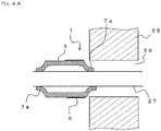
- FIG. 4A is a view showing a state before installing the fire resistant member 1 to a partitioning section 25.
- a through hole 29 is formed in the partitioning section 25, which is a fire prevention partitioning section.
- the partitioning section 25 is a wall or a floor that partitions an inner space of a structure such as a building.
- a long body 27 is inserted into the thorough hole 29 formed in the partitioning section 25.
- the long body 27 is a cable or a pipe, for example.
- a plurality of the long bodies may also be inserted.
- the through hole 29 has a shape corresponding to an outer shape of the cylindrical body 3 of the fire resistant member 1, and the illustration shows the through hole 29 that is in a substantially circular shape.
- the fire resistant member 1 is installed onto the long body 27.
- the fire resistant member 1 has the slit 11.
- the fire resistant member 1 can be easily installed from a side of the long body 27 onto an outer periphery of the long body 27.
- the fire resistant member 1 when the fire resistant member 1 is installed onto the long body 27, the tongue-shaped pieces 7a deform along the long body 27 adhering to the long body 27. Because of this deformation of the tongue-shaped pieces 7a, the fire resistant member 1 can adapt to various size and number of the long body 27.
- the fire resistant member 1 is moved along the long body 27 to be inserted into the through hole 29.
- the metal tape 5 is adhered in the circumferential direction at one of the end part sides of the cylindrical body 3.
- the metal tape 5 enhances rigidity of the corresponding part, and thus crushing or deforming of the cylindrical body 3 can be prevented if the cylindrical body 3 is inserted and pushed into the through hole 29 with the end part side having the metal tape 5 being wound around pointing toward a tip end side of an insertion direction.
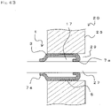
- the long body 27 is in contact with the tongue shaped pieces 7a at a plurality of positions in the axial direction of the cylindrical body 3.
- the tongue-shaped pieces 7a at the tip end side of the insertion direction are folded toward an interior of the cylindrical body 3 as shown in the drawing, so that there are some parts having double layers of the foam body 13a.
- the tongue-shaped pieces 7a can support the long body 27 with certainty.
- the inner diameter of the cylindrical body 3 is larger than an outer diameter of the long body 27 (if there are a plurality of the long bodies 27, a diameter of a circle encircling all the long bodies 27).
- a fire preventing structure 20 including the fire resistant member 1, which is provided in the through hole 29 formed in the partitioning section, and the long body 27, which is inserted into the fire resistant member 1, can be installed.
- the fire resistant member 1 can easily provide the fire preventing structure 20 without using mortar or the like. Also, the fire resistant member 1 is light in weight since the foam body 13a forms most of the fire resistant member 1. Also, since the cylindrical part of the cylindrical body 3 and the tongue-shaped pieces 7a are formed of the foam body 13a as one body, the structure is simple with a small number of components. Also, dispersion of the thermal expansion material 8 inside the cylindrical body 3 can reduce a step of attaching a separate sheet-shaped or putty-like thermally expandable member to the foam body, and this facilitates manufacture of the fire resistant member 1. A thermally expandable putty may also be used on an inner circumference of the cylindrical body 3 at the same time. This can further enhance the thermal expansion performance of the fire resistant member 1.
- the inner diameter of the through hole 29 is approximately the same as or slightly smaller than the outer diameter of the cylindrical body 3.
- the cylindrical body 3 is formed of the foam body 13a and easily deforms.
- an outer periphery surface of the cylindrical body 3 can be adhered to an inner surface of the through hole 29.
- the outer periphery part of the cylindrical body 3 has a part where the cylindrical body 3 is exposed continuously in the circumferential direction without the metal tape 5 being wound around.
- the outer periphery part of the cylindrical body 3 has a cushioning property, absorbing unevenness of the inner periphery surface and errors of the diameter of the through hole 29, and can be adhered to the inner surface of the through hole 29 with certainty.
- the foam body 13a includes the dispersed thermal expansion material 8, the foam body 13a does not slide well against the surface of the long body 27 compared to a typical urethane foam.
- reducing contact area between the long body 27 and the cylindrical body 3 can reduce friction at the time of relative movement and facilitate the movement.
- the outer periphery surface of the cylindrical body 3 contacts with the inner surface of the through hole 29, and at least the tongue-shaped pieces 7a of the cylindrical body 3 contact the long body 27.
- heat transmits from the long body 27 to the foam body 13a, which immediately starts to expand.
- the cylindrical body 3 between the long body 27 and the inner surface of the through hole 29 can seal the through hole 29 with certainty.
- the cylindrical body 3 at the parts corresponding to the space 17 starts expanding later than the tongue-shaped pieces 7a do, at least the tongue-shaped pieces 7a immediately start to expand and seal the thorough hole 29 due to the heat from a side of the fire and the heat from the long body 27, and the entire cylindrical body 3 eventually expands and seals the thorough hole 29 with certainty.
- the tongue-shaped pieces 7a serve as a screen between both sides of the partitioning section 25.
- the tongue-shaped pieces 7a are sufficiently long in length, and thus there are hardly any gaps created among the tongue-shaped pieces 7a when the tongue-shaped pieces 7a are deformed along the long body 27.
- the gap between the tongue-shaped pieces 7a is not formed on a straight line along the axial direction of the through hole 29 since the circumferential positions of the tongue-shaped pieces 7a (the incisions 9a) on both end parts of the cylindrical body 3 are shifted from one another.
- the fire resistant member 1 can also be installed into a substantially rectangular through hole.
- the outer shape of the foam body 13a may be molded into a shape corresponding to the shape of the through hole.
- the fire resistant member 1 is installed after inserting the long body 27 into the through hole 29 in the present embodiment, the long body 27 may be inserted after disposing the fire resistant member 1 inside the through hole 29.
- the slit 11 is unnecessary.
- the metal tape 5 may be wound around after opening the slit 11 and installing the fire resistant member 1 onto the outer periphery of the long body 27. In such a case, the metal tape 5 is wound around the entire periphery and the slit 11 of the foam body 13a may be covered.
- the partitioning section 25 may be a hollow wall.
- the metal tape 5 can serve as a sleeve that seals the hollow part of the hollow wall. This prevents the thermal expansion material 8 from expanding into the hollow part and restricts direction of the expansion.
- FIG. 5A is a side view and FIG. 5B is a front view of a fire resistant member 1a according to the second embodiment.
- FIG. 6 is a cross sectional view taken along F-F line in FIG. 5A .
- structures having the same functions as the fire resistant member 1 will have the same notations as in FIG. 1A to FIG. 4B and redundant descriptions will be omitted.
- the fire resistant member 1a differs from the fire resistant member 1 in that a foam body 13b is further disposed therein.
- a cylindrical body 3a of the fire resistant member 1a is formed by further winding the foam body 13b, which is a second foam body, onto the outer periphery part of the cylindrical body 3 that is formed of the foam body 13a.
- the foam body 13b includes the dispersed thermal expansion material 8.
- the metal tape 5 is wound around the outer periphery of the foam body 13b, which is on the outermost periphery. Also, each of the foam body 13a, the foam body 13b, and the metal tape 5 has the slit 11 formed at the same position.
- the foam body 13a and the foam body 13b are joined together by using an adhesive agent or double sided tape.
- the foam body 13a and the foam body 13b may be joined by stapling or sewing.
- a plurality of incisions 9b are formed at one end part of the foam body 13b, forming tongue-shaped pieces 7b, which are second tongue-shaped pieces.
- the plurality of the tongue-shaped pieces 7b are bent outward at substantially right angles to the axial direction at a side of the one end part of the cylindrical body 3a to form a flange portion 15.
- the foam body 13b is rolled up with the tongue-shaped pieces 7b being bent, and then heated at a temperature below the expansion temperature of the thermal expansion material 8 so as to be molded into the shape.
- a length of the cylindrical portion of the foam body 13a without the tongue-shaped pieces 7a is approximately the same as a length of the cylindrical portion of the foam body 13b without the tongue-shaped pieces 7b.
- the metal tape 5 is disposed on an end part side that is opposite to the end part side where the tongue-shaped pieces 7b are formed, and thus, on the side where the tongue-shaped pieces 7b are formed, the foam body 13b is exposed to an outer surface without the metal tape 5 wound around on the outer periphery of the cylindrical body 3a.
- FIG. 7A is a view showing a state before installing the fire resistant member 1a to the partitioning section 25.
- the through hole 29 is formed in the partitioning section 25, which is a fire preventing section, and then the long body 27 is inserted into the through hole 29.
- the fire resistant member 1a is installed onto the long body 27.
- the slit 11 is provided for each of the fire resistant member 1a, the foam bodies 13a and 13b, and the metal tape 5. By opening up the slits 11, the fire resistant member 1a can be easily installed from a side of the long body 27 onto the outer periphery of the long body 27.
- the metal tape 5 may be wound around the entire periphery after installing the foam bodies 13a and 13b onto the long body 27.
- the fire resistant member 1a is moved along the long body 27 so that the cylindrical body 3b is inserted into the through hole 29.
- an outer diameter of the flange portion 15 is sufficiently larger than the inner diameter of the through hole 29.
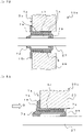
- FIG. 8A is a schematic view showing a state of the fire preventing structure 20a in which a fire starts on a side of the partitioning section 25 where the flange portion 15 is disposed.
- the foam bodies 13a and 13b expand due to heat from the side of the flange portion 15 (an arrow G in the drawing).
- the tongue-shaped pieces 7a and 7b (the flange portion 15) of the fire preventing structure 20a are formed of the foam body 13b including the dispersed thermal expansion material 8.
- the flange portion 15 of the fire preventing structure 20a also expands thermally.
- the tongue-shaped pieces 7a immediately starts expanding at the time of fire since the tongue-shaped pieces 7a are in contact with the long body 27 and are exposed to a room at a high temperature.
- the flange portion 15 also immediately starts expanding since the flange portion 15 is also exposed to the room at the high temperature.
- FIG. 8B is a view showing a sate in which the expansion is further progressed.
- Part of the tongue-shaped pieces 7a of the foam body 13a expand toward an interior of the room, and the other part of the tongue-shaped pieces 7a expand toward the long body 27.
- an outer jacket or the like of the long body 27 may be burned and lost at the time of fire reducing the diameter of the long body 27, even in such the case, the through hole 29 can be sealed with certainty since the foam body 13a expands toward the long body 27.
- the flange portion 15 expands mainly toward the interior of the room. For this reason, when the expansion of the flange portion 15 progresses, an effect as if the through hole 29 is extended can be obtained. This enables to prevent the heat on the one side of the partitioning section 25 from travelling to the opposite side of the partitioning section 25.
- the same effects as in the first embodiment can be obtained. Also, by laying the foam body 13b over the foam body 13a and forming the flange portion 15 by the foam body 13b, the insertion margin of the fire resistant member 1a into the through hole 29 can be easily found, and thus positioning of the cylindrical body 3a in the axial direction against the through hole 29 can be easily determined.
- the flange portion 15 is formed of a member that is different from the tongue-shaped pieces 7a, the flange portion 15 stays in shape unaffected by the deformation of the tongue-shaped pieces 7a. Also, since the flange portion 15 includes the thermal expansion material 8, the flange portion 15 can thermally expand toward the interior of the room at the time of fire and can provide an effect of extension of the through hole 29.
- the flange portion 15 is formed of a foam body and thus can be crushed easily.
- the partitioning section 25 is a floor part and the fire resistant member 1a is disposed from an upper side of the floor, a part of the fire resistant member 1a protrudes from an upper surface of the partitioning section 25 for a thickness of the flange portion 15.
- the flange portion 15 can be easily crushed, so installing a floorboard, for example, can suppress the protrusion at a region of the flange portion 15.
- metal tape or the like can be attached on a rear side of the flange portion 15 (a surface contacting with the partitioning section 25). This can increase rigidity of the flange portion 15.
- FIG. 9A is a view showing a fire preventing structure 20b using a fire resistant member 1b according to the third embodiment.
- the fire resistant member 1b has almost the same structure as the fire resistant member 1a except that a foam body 13c, which is a third foam body, is attached inside the cylindrical body 3a.
- the foam body 13c includes the dispersed thermal expansion material 8.
- the foam body 13c and the foam body 13a are joined together by using an adhesive agent or double sided tape, for example. Also, the foam body 13c includes the slit 11 formed at the same position as in the foam bodies 13a, 13b and the metal tape 5.
- the foam body 13c may also be single-layered or three or more layered. Also, in the fire preventing structure 20b, although not limited thereto, the foam body 13c is disposed over substantially the entire longitudinal direction of the cylindrical body 3a and an innermost periphery surface of the foam body 13c is in contact with the long body 27.
- the foam body 13c may be divided and disposed at some parts of the inner surface of the cylindrical body 3a.
- the foam body 13c is disposed at proximity of each end part of the cylindrical body 3a, whereas at the substantial center part of the axial direction of the cylindrical body 3a, the foam body 13c is not disposed and the space 17 is formed.
- the same effects as in the second embodiment can be obtained.
- using the foam body 13c can seal the through hole 29 with certainty by expansion of the foam body 13c even when the space 17 is too large and an amount of expansion of the foam body 13a and the like is insufficient.
- dividing the foam body 13c and leaving the space 17 at some parts can decrease the contacting area between the foam body 13c and the long body 27, which can facilitate the relative movement of the fire resistant member 1c against the long body 27.
- the foam body 13c can provide the screen effect between the inside and outside of the partitioning section 25 with more certainty.
- the foam body 13c is disposed inside the cylindrical body 3a in the present embodiment, the foam body 13c may be disposed inside the cylindrical body 3. Also, the foam body 13c may be disposed on the outer periphery of the foam body 13a or on the outer periphery of the foam body 13b. Also, instead of the foam body 13c, or in addition to the foam body 13c, thermally expandable putty may be used inside the cylindrical body 3a. This can also improve the thermal expansion performance.
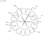
- FIG. 10A is a side view showing a fire resistant member 1d according to the fourth embodiment
- FIG. 10B is a front view of the fire resistant member Id.
- the fire resistant member 1d has almost the same structure as the fire resistant member 1a except that the cylindrical body 3b is formed only of the foam body 13a.
- the foam body 13a is rolled up to be in a cylindrical shape.
- the plurality of the tongue-shaped pieces 7a are formed at each end part of the cylindrical body, and the tongue-shaped pieces 7a are bent toward the center.
- the tongue-shaped pieces 7b that are to be bent toward the outer side are formed between the tongue-shaped pieces 7a.
- the tongue-shaped pieces 7b are bent substantially vertically to the axial direction of the cylindrical body 3b to form the flange portion 15.
- FIG. 11 is a development view of the foam body 13a for forming the cylindrical body 3b.
- a dotted line X in the drawing is a part where the tongue-shaped piece 7a is bent, and a dotted line Y in the drawing is a part where the tongue-shaped piece 7b is bent.
- the bending directions at the dotted line X and the dotted line Y are opposite from each other.
- incisions 9c are formed and the tongue-shaped pieces 7a and 7b are formed alternately.
- the tongue-shaped pieces 7a and 7b may not always alternate with each other.
- the tongue-shaped piece 7a is formed in a generally triangular shape with a narrower width toward a tip end of the triangle, and the tongue-shaped pieces 7a are formed at a predetermined pitch in a longitudinal direction of the foam body 13a (the direction corresponding to the circumferential direction of the cylindrical body 3b).
- the tongue-shaped piece 7b is in a generally rectangular shape, and the tongue-shaped pieces 7b are formed at a predetermined pitch in a longitudinal direction of the foam body 13a (the direction corresponding to the circumferential direction of the cylindrical body 3b).
- a width of the tongue-shaped piece 7b may be narrower than a base width of the tongue-shaped piece 7a.
- the other end part side of the foam body 13a (a right side in the drawing) is similar to the one shown in FIG. 3 .
- the forming pitch of the tongue-shaped pieces 7a in the longitudinal direction of the foam body 13a is the same at both ends of a width direction of the foam body 13a.
- the tongue-shaped pieces 7a are formed so that the forming positions of the tongue-shaped pieces 7a in the longitudinal direction on the one end part of the foam body 13a and the forming positions of the tongue-shaped pieces 7a in the longitudinal direction on the other end part of the foam body 13a are shifted from each other.
- the same effects as in the second embodiment can be obtained.
- the flange portion 15 can be formed without a plurality of layers of the foam body 13b, allowing the structure to be simpler.
- FIG. 12A is a front view of a fire resistant member 1e according to the fifth embodiment
- FIG. 12B is a cross sectional view taken along H-H line in FIG. 12A
- the fire resistant member 1e has the same structure as the fire resistant member 1 and the like in regard to the slit 11 and the metal tape 5.
- the tongue-shaped pieces 7a of the fire resistant member 1e are formed, not by bending the both ends of the cylindrical body, but separately from a cylindrical body 3c.
- the foam body 13a is rolled up to form the cylindrical body 3c.
- the plurality of layers of the foam body 13a are disposed.
- the plurality of the tongue-shaped pieces 7a are disposed in the circumferential direction, pointing toward the center, at a plurality of parts of the axial direction of the cylindrical body 3c.
- a hole 33 is formed in the cylindrical body 3c, and an insertion portion 31, which is formed on a rear end side of the tongue-shaped piece 7a, is inserted into the hole 33 and fixed to the cylindrical body 3c.
- the tongue-shaped pieces 7a may be disposed at three places along the axial direction of the cylindrical body 3c as shown in the illustrations, or may be disposed at two places, or may be disposed at four or more places. Also, the tongue-shaped pieces 7a may be fixed by joining to an inner surface of the cylindrical body 3c using an adhesive agent or the like.
- the inserting portion 31 of the tongue-shaped pieces 7a disposed on one end part side of the cylindrical body 3c is formed to have a length that is larger than a thickness of the cylindrical body 3c. Thus, a part of the inserting portion 31 protrudes to an outer part of the cylindrical body 3c.
- the protruding inserting portion 31 can serve as the flange portion 15.
- the length of the inserting portion 31 of the tongue-shaped pieces 7a at the other parts are set to be equal to or less than the thickness of the cylindrical body 3c. Thus, the inserting portion 31 does not protrude from the cylindrical body 3c.
- the flange portion 15 is not always necessary.
- a protruding length of each of the tongue-shaped pieces 7a from the inner surface of the cylindrical body 3c is preferably half of the inner diameter of the cylindrical body 3c or more.
- the length of the tongue-shaped piece 7a is larger than the half of the inner diameter of the cylindrical body 3c.
- the forming position in the circumferential direction of the tongue-shaped pieces 7a at a part of the axial direction of the cylindrical body 3c and the forming position in the circumferential direction of the tongue-shaped pieces 7a at the other part of the axial direction of the cylindrical body 3c are shifted from each other.
- each of the tongue-shaped pieces 7a can be formed at positions other than the end parts of the cylindrical body 3c.
- each embodiment can be combined with each other.
- another layer of the foam body 13c may be further disposed.
- the hole 33 may be formed at positions other than the end parts and the tongue-shaped pieces 7a may be further disposed therein.
- the cylindrical body is formed by rolling up the foam body, rolling is not always necessary to form the cylindrical body.
- the cylindrical body may be formed by extrusion molding. In such the case, the slit may be formed along the axial direction of the cylindrical body to form an opening. That is, any method that can form the cylindrical body from the foam body may be used.
Landscapes
- Engineering & Computer Science (AREA)
- Architecture (AREA)
- Civil Engineering (AREA)
- Structural Engineering (AREA)
- Health & Medical Sciences (AREA)
- Public Health (AREA)
- Business, Economics & Management (AREA)
- Emergency Management (AREA)
- General Engineering & Computer Science (AREA)
- Mechanical Engineering (AREA)
- Building Environments (AREA)
- Installation Of Indoor Wiring (AREA)
Applications Claiming Priority (2)
| Application Number | Priority Date | Filing Date | Title |
|---|---|---|---|
| JP2019097138 | 2019-05-23 | ||
| PCT/JP2020/019751 WO2020235549A1 (ja) | 2019-05-23 | 2020-05-19 | 耐火部材、防火構造体および防火構造体の施工方法 |
Publications (2)
| Publication Number | Publication Date |
|---|---|
| EP3974033A1 true EP3974033A1 (de) | 2022-03-30 |
| EP3974033A4 EP3974033A4 (de) | 2023-06-21 |
Family
ID=73459409
Family Applications (1)
| Application Number | Title | Priority Date | Filing Date |
|---|---|---|---|
| EP20809057.1A Withdrawn EP3974033A4 (de) | 2019-05-23 | 2020-05-19 | Feuerbeständiges element, feuerschutzstruktur und verfahren zur installation einer brandschutzstruktur |
Country Status (3)
| Country | Link |
|---|---|
| EP (1) | EP3974033A4 (de) |
| JP (1) | JP7479298B2 (de) |
| WO (1) | WO2020235549A1 (de) |
Families Citing this family (2)
| Publication number | Priority date | Publication date | Assignee | Title |
|---|---|---|---|---|
| JP7311333B2 (ja) * | 2019-07-04 | 2023-07-19 | 未来工業株式会社 | 隙間処理部材及び区画体の貫通孔処理構造 |
| JP2025151502A (ja) * | 2024-03-28 | 2025-10-09 | 三菱重工業株式会社 | シール構造、建屋及びシール構造の製造方法 |
Family Cites Families (9)
| Publication number | Priority date | Publication date | Assignee | Title |
|---|---|---|---|---|
| GB2233725B (en) * | 1989-07-07 | 1992-11-25 | Arthur Peter Hamilton | Fire stop collars for combustible pipes |
| JP2550381Y2 (ja) * | 1990-04-24 | 1997-10-08 | 古河電気工業株式会社 | 床や壁等の防火区画体における電線、電線管等の貫通部の防火措置構造 |
| JP2540911Y2 (ja) * | 1991-09-30 | 1997-07-09 | 古河電気工業株式会社 | 防火区画体における可燃材製長尺管体貫通部の防火構造 |
| JPH09262305A (ja) | 1996-03-28 | 1997-10-07 | Furukawa Techno Material:Kk | 防火区画体貫通部の防火処理用シート及び防火処理構造 |
| JP5301851B2 (ja) * | 2008-02-21 | 2013-09-25 | 未来工業株式会社 | スリーブ形成シート及び貫通部構造の形成方法 |
| JP5916533B2 (ja) * | 2012-06-26 | 2016-05-11 | 未来工業株式会社 | 中空壁における貫通孔の耐火構造及び充填材受け具 |
| JP6097737B2 (ja) | 2014-12-18 | 2017-03-15 | 株式会社古河テクノマテリアル | 耐火部材、防火構造体、構造物および防火構造体の施工方法 |
| JP6837736B2 (ja) * | 2015-06-01 | 2021-03-03 | 積水化学工業株式会社 | 貫通孔カバー、及び区画貫通孔の防火構造 |
| JP6150933B2 (ja) * | 2015-10-02 | 2017-06-21 | 因幡電機産業株式会社 | 貫通孔措置ユニット及び貫通孔措置構造 |
-
2020
- 2020-05-19 JP JP2020560426A patent/JP7479298B2/ja active Active
- 2020-05-19 WO PCT/JP2020/019751 patent/WO2020235549A1/ja not_active Ceased
- 2020-05-19 EP EP20809057.1A patent/EP3974033A4/de not_active Withdrawn
Also Published As
| Publication number | Publication date |
|---|---|
| WO2020235549A1 (ja) | 2020-11-26 |
| EP3974033A4 (de) | 2023-06-21 |
| JPWO2020235549A1 (de) | 2020-11-26 |
| JP7479298B2 (ja) | 2024-05-08 |
Similar Documents
| Publication | Publication Date | Title |
|---|---|---|
| JP6097737B2 (ja) | 耐火部材、防火構造体、構造物および防火構造体の施工方法 | |
| JP4933412B2 (ja) | 熱膨張性耐火具及び耐火構造 | |
| JP6895808B2 (ja) | 耐火部材、防火構造体および防火構造体の施工方法 | |
| EP3974033A1 (de) | Feuerbeständiges element, feuerschutzstruktur und verfahren zur installation einer brandschutzstruktur | |
| JP6508983B2 (ja) | 防火措置構造 | |
| JP6429910B2 (ja) | 耐火部材、防火構造体、構造物および防火構造体の施工方法 | |
| US20030172603A1 (en) | Fire collar | |
| EP3903891A1 (de) | Feuerbeständiges element | |
| JP6978961B2 (ja) | 耐火構造、耐火具及び閉塞部材 | |
| JP7320577B2 (ja) | 耐火具および閉塞部材 | |
| JP7508435B2 (ja) | 耐火構造 | |
| JP2023052087A (ja) | 耐火部材 | |
| JP7168547B2 (ja) | 耐火部材、耐火構造 | |
| JP2019141335A (ja) | 耐火構造、耐火具及び閉塞部材 | |
| JP4060844B2 (ja) | 区画貫通部の防火措置構造 | |
| JP4950503B2 (ja) | 防火用充填材支持金具 | |
| JP3435090B2 (ja) | 閉塞材支持具 | |
| JP7320576B2 (ja) | 耐火具及び閉塞部材 | |
| JP3883913B2 (ja) | 防火区画体の貫通構造及び同貫通構造を形成する貫通筒体 | |
| US20250144456A1 (en) | Wrap Strip Tuck-In Apparatus | |
| JP7097484B1 (ja) | 耐火部材、耐火構造 | |
| NL2035922B1 (en) | Casing strip for a firestop sleeve | |
| JP2006016967A (ja) | 耐火充填材 | |
| US12329998B2 (en) | Passive fire protection device | |
| JP7458461B1 (ja) | 熱膨張材取付具及び耐火区画貫通具 |
Legal Events
| Date | Code | Title | Description |
|---|---|---|---|
| STAA | Information on the status of an ep patent application or granted ep patent |
Free format text: STATUS: THE INTERNATIONAL PUBLICATION HAS BEEN MADE |
|
| PUAI | Public reference made under article 153(3) epc to a published international application that has entered the european phase |
Free format text: ORIGINAL CODE: 0009012 |
|
| STAA | Information on the status of an ep patent application or granted ep patent |
Free format text: STATUS: REQUEST FOR EXAMINATION WAS MADE |
|
| 17P | Request for examination filed |
Effective date: 20210330 |
|
| AK | Designated contracting states |
Kind code of ref document: A1 Designated state(s): AL AT BE BG CH CY CZ DE DK EE ES FI FR GB GR HR HU IE IS IT LI LT LU LV MC MK MT NL NO PL PT RO RS SE SI SK SM TR |
|
| DAV | Request for validation of the european patent (deleted) | ||
| DAX | Request for extension of the european patent (deleted) | ||
| A4 | Supplementary search report drawn up and despatched |
Effective date: 20230523 |
|
| RIC1 | Information provided on ipc code assigned before grant |
Ipc: H02G 3/04 20060101ALI20230516BHEP Ipc: A62C 2/06 20060101ALI20230516BHEP Ipc: H02G 3/22 20060101ALI20230516BHEP Ipc: F16L 5/04 20060101ALI20230516BHEP Ipc: E04B 1/94 20060101ALI20230516BHEP Ipc: A62C 3/16 20060101AFI20230516BHEP |
|
| STAA | Information on the status of an ep patent application or granted ep patent |
Free format text: STATUS: THE APPLICATION HAS BEEN WITHDRAWN |
|
| 18W | Application withdrawn |
Effective date: 20240502 |