EP3974232B1 - System zur ladungs-/entladungssteuerung - Google Patents
System zur ladungs-/entladungssteuerung Download PDFInfo
- Publication number
- EP3974232B1 EP3974232B1 EP21197011.6A EP21197011A EP3974232B1 EP 3974232 B1 EP3974232 B1 EP 3974232B1 EP 21197011 A EP21197011 A EP 21197011A EP 3974232 B1 EP3974232 B1 EP 3974232B1
- Authority
- EP
- European Patent Office
- Prior art keywords
- battery
- voltage
- level
- switch
- charge
- Prior art date
- Legal status (The legal status is an assumption and is not a legal conclusion. Google has not performed a legal analysis and makes no representation as to the accuracy of the status listed.)
- Active
Links
Images



Classifications
-
- B—PERFORMING OPERATIONS; TRANSPORTING
- B60—VEHICLES IN GENERAL
- B60L—PROPULSION OF ELECTRICALLY-PROPELLED VEHICLES; SUPPLYING ELECTRIC POWER FOR AUXILIARY EQUIPMENT OF ELECTRICALLY-PROPELLED VEHICLES; ELECTRODYNAMIC BRAKE SYSTEMS FOR VEHICLES IN GENERAL; MAGNETIC SUSPENSION OR LEVITATION FOR VEHICLES; MONITORING OPERATING VARIABLES OF ELECTRICALLY-PROPELLED VEHICLES; ELECTRIC SAFETY DEVICES FOR ELECTRICALLY-PROPELLED VEHICLES
- B60L1/00—Supplying electric power to auxiliary equipment of vehicles
- B60L1/14—Supplying electric power to auxiliary equipment of vehicles to electric lighting circuits
-
- B—PERFORMING OPERATIONS; TRANSPORTING
- B60—VEHICLES IN GENERAL
- B60L—PROPULSION OF ELECTRICALLY-PROPELLED VEHICLES; SUPPLYING ELECTRIC POWER FOR AUXILIARY EQUIPMENT OF ELECTRICALLY-PROPELLED VEHICLES; ELECTRODYNAMIC BRAKE SYSTEMS FOR VEHICLES IN GENERAL; MAGNETIC SUSPENSION OR LEVITATION FOR VEHICLES; MONITORING OPERATING VARIABLES OF ELECTRICALLY-PROPELLED VEHICLES; ELECTRIC SAFETY DEVICES FOR ELECTRICALLY-PROPELLED VEHICLES
- B60L50/00—Electric propulsion with power supplied within the vehicle
- B60L50/50—Electric propulsion with power supplied within the vehicle using propulsion power supplied by batteries or fuel cells
- B60L50/60—Electric propulsion with power supplied within the vehicle using propulsion power supplied by batteries or fuel cells using power supplied by batteries
-
- B—PERFORMING OPERATIONS; TRANSPORTING
- B60—VEHICLES IN GENERAL
- B60L—PROPULSION OF ELECTRICALLY-PROPELLED VEHICLES; SUPPLYING ELECTRIC POWER FOR AUXILIARY EQUIPMENT OF ELECTRICALLY-PROPELLED VEHICLES; ELECTRODYNAMIC BRAKE SYSTEMS FOR VEHICLES IN GENERAL; MAGNETIC SUSPENSION OR LEVITATION FOR VEHICLES; MONITORING OPERATING VARIABLES OF ELECTRICALLY-PROPELLED VEHICLES; ELECTRIC SAFETY DEVICES FOR ELECTRICALLY-PROPELLED VEHICLES
- B60L53/00—Methods of charging batteries, specially adapted for electric vehicles; Charging stations or on-board charging equipment therefor; Exchange of energy storage elements in electric vehicles
- B60L53/50—Charging stations characterised by energy-storage or power-generation means
- B60L53/51—Photovoltaic means
-
- B—PERFORMING OPERATIONS; TRANSPORTING
- B60—VEHICLES IN GENERAL
- B60L—PROPULSION OF ELECTRICALLY-PROPELLED VEHICLES; SUPPLYING ELECTRIC POWER FOR AUXILIARY EQUIPMENT OF ELECTRICALLY-PROPELLED VEHICLES; ELECTRODYNAMIC BRAKE SYSTEMS FOR VEHICLES IN GENERAL; MAGNETIC SUSPENSION OR LEVITATION FOR VEHICLES; MONITORING OPERATING VARIABLES OF ELECTRICALLY-PROPELLED VEHICLES; ELECTRIC SAFETY DEVICES FOR ELECTRICALLY-PROPELLED VEHICLES
- B60L53/00—Methods of charging batteries, specially adapted for electric vehicles; Charging stations or on-board charging equipment therefor; Exchange of energy storage elements in electric vehicles
- B60L53/50—Charging stations characterised by energy-storage or power-generation means
- B60L53/52—Wind-driven generators
-
- B—PERFORMING OPERATIONS; TRANSPORTING
- B60—VEHICLES IN GENERAL
- B60L—PROPULSION OF ELECTRICALLY-PROPELLED VEHICLES; SUPPLYING ELECTRIC POWER FOR AUXILIARY EQUIPMENT OF ELECTRICALLY-PROPELLED VEHICLES; ELECTRODYNAMIC BRAKE SYSTEMS FOR VEHICLES IN GENERAL; MAGNETIC SUSPENSION OR LEVITATION FOR VEHICLES; MONITORING OPERATING VARIABLES OF ELECTRICALLY-PROPELLED VEHICLES; ELECTRIC SAFETY DEVICES FOR ELECTRICALLY-PROPELLED VEHICLES
- B60L53/00—Methods of charging batteries, specially adapted for electric vehicles; Charging stations or on-board charging equipment therefor; Exchange of energy storage elements in electric vehicles
- B60L53/50—Charging stations characterised by energy-storage or power-generation means
- B60L53/57—Charging stations without connection to power networks
-
- B—PERFORMING OPERATIONS; TRANSPORTING
- B60—VEHICLES IN GENERAL
- B60L—PROPULSION OF ELECTRICALLY-PROPELLED VEHICLES; SUPPLYING ELECTRIC POWER FOR AUXILIARY EQUIPMENT OF ELECTRICALLY-PROPELLED VEHICLES; ELECTRODYNAMIC BRAKE SYSTEMS FOR VEHICLES IN GENERAL; MAGNETIC SUSPENSION OR LEVITATION FOR VEHICLES; MONITORING OPERATING VARIABLES OF ELECTRICALLY-PROPELLED VEHICLES; ELECTRIC SAFETY DEVICES FOR ELECTRICALLY-PROPELLED VEHICLES
- B60L58/00—Methods or circuit arrangements for monitoring or controlling batteries or fuel cells, specially adapted for electric vehicles
- B60L58/10—Methods or circuit arrangements for monitoring or controlling batteries or fuel cells, specially adapted for electric vehicles for monitoring or controlling batteries
- B60L58/12—Methods or circuit arrangements for monitoring or controlling batteries or fuel cells, specially adapted for electric vehicles for monitoring or controlling batteries responding to state of charge [SoC]
- B60L58/14—Preventing excessive discharging
-
- B—PERFORMING OPERATIONS; TRANSPORTING
- B60—VEHICLES IN GENERAL
- B60L—PROPULSION OF ELECTRICALLY-PROPELLED VEHICLES; SUPPLYING ELECTRIC POWER FOR AUXILIARY EQUIPMENT OF ELECTRICALLY-PROPELLED VEHICLES; ELECTRODYNAMIC BRAKE SYSTEMS FOR VEHICLES IN GENERAL; MAGNETIC SUSPENSION OR LEVITATION FOR VEHICLES; MONITORING OPERATING VARIABLES OF ELECTRICALLY-PROPELLED VEHICLES; ELECTRIC SAFETY DEVICES FOR ELECTRICALLY-PROPELLED VEHICLES
- B60L58/00—Methods or circuit arrangements for monitoring or controlling batteries or fuel cells, specially adapted for electric vehicles
- B60L58/10—Methods or circuit arrangements for monitoring or controlling batteries or fuel cells, specially adapted for electric vehicles for monitoring or controlling batteries
- B60L58/16—Methods or circuit arrangements for monitoring or controlling batteries or fuel cells, specially adapted for electric vehicles for monitoring or controlling batteries responding to battery ageing, e.g. to the number of charging cycles or the state of health [SoH]
-
- B—PERFORMING OPERATIONS; TRANSPORTING
- B60—VEHICLES IN GENERAL
- B60L—PROPULSION OF ELECTRICALLY-PROPELLED VEHICLES; SUPPLYING ELECTRIC POWER FOR AUXILIARY EQUIPMENT OF ELECTRICALLY-PROPELLED VEHICLES; ELECTRODYNAMIC BRAKE SYSTEMS FOR VEHICLES IN GENERAL; MAGNETIC SUSPENSION OR LEVITATION FOR VEHICLES; MONITORING OPERATING VARIABLES OF ELECTRICALLY-PROPELLED VEHICLES; ELECTRIC SAFETY DEVICES FOR ELECTRICALLY-PROPELLED VEHICLES
- B60L58/00—Methods or circuit arrangements for monitoring or controlling batteries or fuel cells, specially adapted for electric vehicles
- B60L58/10—Methods or circuit arrangements for monitoring or controlling batteries or fuel cells, specially adapted for electric vehicles for monitoring or controlling batteries
- B60L58/18—Methods or circuit arrangements for monitoring or controlling batteries or fuel cells, specially adapted for electric vehicles for monitoring or controlling batteries of two or more battery modules
-
- B—PERFORMING OPERATIONS; TRANSPORTING
- B60—VEHICLES IN GENERAL
- B60L—PROPULSION OF ELECTRICALLY-PROPELLED VEHICLES; SUPPLYING ELECTRIC POWER FOR AUXILIARY EQUIPMENT OF ELECTRICALLY-PROPELLED VEHICLES; ELECTRODYNAMIC BRAKE SYSTEMS FOR VEHICLES IN GENERAL; MAGNETIC SUSPENSION OR LEVITATION FOR VEHICLES; MONITORING OPERATING VARIABLES OF ELECTRICALLY-PROPELLED VEHICLES; ELECTRIC SAFETY DEVICES FOR ELECTRICALLY-PROPELLED VEHICLES
- B60L58/00—Methods or circuit arrangements for monitoring or controlling batteries or fuel cells, specially adapted for electric vehicles
- B60L58/10—Methods or circuit arrangements for monitoring or controlling batteries or fuel cells, specially adapted for electric vehicles for monitoring or controlling batteries
- B60L58/18—Methods or circuit arrangements for monitoring or controlling batteries or fuel cells, specially adapted for electric vehicles for monitoring or controlling batteries of two or more battery modules
- B60L58/22—Balancing the charge of battery modules
-
- H—ELECTRICITY
- H02—GENERATION; CONVERSION OR DISTRIBUTION OF ELECTRIC POWER
- H02J—ELECTRIC POWER NETWORKS; CIRCUIT ARRANGEMENTS OR SYSTEMS FOR SUPPLYING OR DISTRIBUTING ELECTRIC POWER; SYSTEMS FOR STORING ELECTRIC ENERGY
- H02J7/00—Circuit arrangements for charging or discharging batteries or for supplying loads from batteries
- H02J7/50—Circuit arrangements for charging or discharging batteries or for supplying loads from batteries acting upon multiple batteries simultaneously or sequentially
- H02J7/52—Circuit arrangements for charging or discharging batteries or for supplying loads from batteries acting upon multiple batteries simultaneously or sequentially for charge balancing, e.g. equalisation of charge between batteries
-
- H—ELECTRICITY
- H02—GENERATION; CONVERSION OR DISTRIBUTION OF ELECTRIC POWER
- H02J—ELECTRIC POWER NETWORKS; CIRCUIT ARRANGEMENTS OR SYSTEMS FOR SUPPLYING OR DISTRIBUTING ELECTRIC POWER; SYSTEMS FOR STORING ELECTRIC ENERGY
- H02J7/00—Circuit arrangements for charging or discharging batteries or for supplying loads from batteries
- H02J7/80—Circuit arrangements for charging or discharging batteries or for supplying loads from batteries including monitoring or indicating arrangements
- H02J7/82—Control of state of charge [SOC]
-
- B—PERFORMING OPERATIONS; TRANSPORTING
- B60—VEHICLES IN GENERAL
- B60L—PROPULSION OF ELECTRICALLY-PROPELLED VEHICLES; SUPPLYING ELECTRIC POWER FOR AUXILIARY EQUIPMENT OF ELECTRICALLY-PROPELLED VEHICLES; ELECTRODYNAMIC BRAKE SYSTEMS FOR VEHICLES IN GENERAL; MAGNETIC SUSPENSION OR LEVITATION FOR VEHICLES; MONITORING OPERATING VARIABLES OF ELECTRICALLY-PROPELLED VEHICLES; ELECTRIC SAFETY DEVICES FOR ELECTRICALLY-PROPELLED VEHICLES
- B60L2240/00—Control parameters of input or output; Target parameters
- B60L2240/40—Drive Train control parameters
- B60L2240/54—Drive Train control parameters related to batteries
- B60L2240/547—Voltage
-
- Y—GENERAL TAGGING OF NEW TECHNOLOGICAL DEVELOPMENTS; GENERAL TAGGING OF CROSS-SECTIONAL TECHNOLOGIES SPANNING OVER SEVERAL SECTIONS OF THE IPC; TECHNICAL SUBJECTS COVERED BY FORMER USPC CROSS-REFERENCE ART COLLECTIONS [XRACs] AND DIGESTS
- Y02—TECHNOLOGIES OR APPLICATIONS FOR MITIGATION OR ADAPTATION AGAINST CLIMATE CHANGE
- Y02T—CLIMATE CHANGE MITIGATION TECHNOLOGIES RELATED TO TRANSPORTATION
- Y02T10/00—Road transport of goods or passengers
- Y02T10/60—Other road transportation technologies with climate change mitigation effect
- Y02T10/70—Energy storage systems for electromobility, e.g. batteries
-
- Y—GENERAL TAGGING OF NEW TECHNOLOGICAL DEVELOPMENTS; GENERAL TAGGING OF CROSS-SECTIONAL TECHNOLOGIES SPANNING OVER SEVERAL SECTIONS OF THE IPC; TECHNICAL SUBJECTS COVERED BY FORMER USPC CROSS-REFERENCE ART COLLECTIONS [XRACs] AND DIGESTS
- Y02—TECHNOLOGIES OR APPLICATIONS FOR MITIGATION OR ADAPTATION AGAINST CLIMATE CHANGE
- Y02T—CLIMATE CHANGE MITIGATION TECHNOLOGIES RELATED TO TRANSPORTATION
- Y02T10/00—Road transport of goods or passengers
- Y02T10/60—Other road transportation technologies with climate change mitigation effect
- Y02T10/7072—Electromobility specific charging systems or methods for batteries, ultracapacitors, supercapacitors or double-layer capacitors
-
- Y—GENERAL TAGGING OF NEW TECHNOLOGICAL DEVELOPMENTS; GENERAL TAGGING OF CROSS-SECTIONAL TECHNOLOGIES SPANNING OVER SEVERAL SECTIONS OF THE IPC; TECHNICAL SUBJECTS COVERED BY FORMER USPC CROSS-REFERENCE ART COLLECTIONS [XRACs] AND DIGESTS
- Y02—TECHNOLOGIES OR APPLICATIONS FOR MITIGATION OR ADAPTATION AGAINST CLIMATE CHANGE
- Y02T—CLIMATE CHANGE MITIGATION TECHNOLOGIES RELATED TO TRANSPORTATION
- Y02T90/00—Enabling technologies or technologies with a potential or indirect contribution to GHG emissions mitigation
- Y02T90/10—Technologies relating to charging of electric vehicles
- Y02T90/12—Electric charging stations
Definitions
- the present invention relates to a charge/discharge control system.
- JP 2019-208309 A discloses a drive control system for an electrical vehicle.
- a plurality of battery packs connected in parallel to each other are simultaneously used, causing a more amount of electrical current to flow to the electrical load from one of the battery packs of which a wiring length to the electrical load is relatively short than that from another of the batter packs of which a wiring length to the electrical load is relatively long, according to difference of wiring resistance between the wiring lengths.
- the drive control system of JP 2019-208309 A intends to alleviate such a problem.
- the drive control system includes a battery control unit, a power supply unit, and a power capacity acquisition unit.
- the battery control unit works to select one of the battery packs as a batter pack for driving.
- the power supply unit delivers electrical power from the drive battery pack to an electrical motor.
- the power capacity acquisition unit works to acquire an information as to power capacity of the selected battery pack. When the power capacity of the selected battery pack becomes equal to or less than a given value, the battery control unit of the drive control system selects another of the battery packs as a battery pack for driving.
- a battery module balancing system in a vehicle having a powertrain system includes a battery pack having at least one battery module, an electric generator for generating and providing a second voltage, a low voltage battery for storing or providing a first voltage and a controller being operable to balance a state-of-charge (SOC) in the battery module.
- the battery pack including the battery module has an energy for providing power to the powertrain system of the vehicle.
- the controller determines to charge or discharge the battery module for balancing the SOC in each battery module based on each mode of the balancing system.
- CN 110 417 068 A discloses a charging device and a charging method thereof.
- the charging device comprises a connecting port, a charging unit, a plurality of switch modules and a processing unit; the charging method comprises the following steps that a plurality of battery voltages of a plurality of battery packs are measured sequentially through a plurality of switch modules, the switch module which is coupled to the battery pack with the lowest battery voltage is conducted so as to enable the battery pack with the lowest battery voltage to be electrically connected to the charging unit, the charging unit is started to supply power, and when the battery pack with the lowest battery voltage is charged to the battery voltage of one of the battery packs, the switch module corresponding to the reached battery voltage is conducted.
- the above drive control system works only to switch, for driving, from one to another of the battery packs when the power capacity becomes equal to or less than the given value, but is not designed to minimize, in consideration of the frequency of uses thereof, an imbalance in degree of deterioration among the battery packs.
- the present invention has been made in view of the above problems. It is an object of the invention to provide a charge/discharge control system capable of minimizing an imbalance in frequency of uses among the battery modules and reducing an imbalance in degree of deterioration among the battery modules.
- a charge/discharge control system capable of minimizing an imbalance in frequency of uses among the battery modules and reducing an imbalance in degree of deterioration among the battery modules.
- a charge/discharge control system in an embodiment of the invention includes: a power generating unit; an electrical load; a plurality of battery modules; a first connecting path with which the battery modules are connected in parallel to each other; a first switch which is disposed among the first connecting path, the power generating unit, and the electrical load and switchable between an on-state in which the first connecting path is connected with the power generating unit or the electrical load and an off-state in which the first connecting path is disconnected from the power generating unit and the electrical load; and a controller which is supplied with electrical power from the power generating unit or the battery modules, wherein each of the battery modules includes a battery, a second switch which is switchable between an on-state in which the battery is connected with the first connecting path and an off-state in which the battery is disconnected from the first connecting path, and a battery management device which controls a state of the battery and a switching operation of the second switch, a third switch is disposed between each of the battery management devices and the first connecting path, the third switch being switchable between an on
- the charge/discharge control system 1 includes a power generating unit 2, an electrical load 3, a plurality of battery modules 4, a first connecting path 5, a first switch 6, and a controller 7.
- the charge/discharge control system 1 is equipped with the n battery modules 4.
- the n battery modules 4 includes battery modules 4a to 4n.
- each of the battery modules 4a to 4n will also be merely referred to as the battery module 4 unless discriminated from the others.
- the power generating unit 2 is a power generator, such as a solar photovoltaic unit or a wind power generator, which generates electricity using renewable energy.
- the power generating unit 2 may be a hydroelectric generator, a geothermal power generator, or a biomass power generator, which generates electricity using renewable energy.
- the electrical load 3 includes an electrical device equipped with a light emitter, such as a light or an electronic message board, but is not limited to the electrical device.
- Each battery module 4 includes a battery 41, a second switch 42, and a battery management device 43.
- the batteries 41, the second switches 42, and the battery management devices 43 will also be denoted with alphabetic suffixes "a" to "n” corresponding to the respective battery modules 4a to 4n.
- each battery, each second switch, and each battery management device will also be merely referred to as the battery 41, the second switch 42, and the battery management device 43 unless discriminated from the others.
- Each of the batteries 41 is a rechargeable/dischargeable secondary battery, such as a lithium-ion battery. Lithium-ion batteries mounted and used in a vehicle may be reused as the batteries 41.
- Each of the second switches 42 is configured to switch between an on-state in which the battery 41 and the first connecting path 5 are connected to each other and an off-state in which these are disconnected from each other.
- Each of the second switches 42 is controlled by a corresponding one of the battery management devices 43, so as to switch between the on- and off-states of the second switch 42.
- Each of the battery management devices 43 is designed to monitor and control the state of a corresponding one of the batteries 41, such as the level of voltage developed at the battery 41 or the amount of electrical energy remaining in the battery 41, e.g., a SOC (i.e., state of charge) thereof.
- the battery management device 43 works to switch between an on-state and an off-state of the second switch 42.
- the battery management device 43 calculates the SOC of the battery 41, using an amount of current charged in or discharged from the battery 41.
- the battery management device 43 is connected to the controller 7 to output information about, for example, the level of voltage developed at the battery 41 and the SOC of the battery 41, to the controller 7.
- the third switch 8 is disposed between each of the battery management devices 43 and the first connecting path 5.
- the third switch 8 is selectively placed in an on-state to connect or an off-state to disconnect between the battery management device 43 and the first connecting path 5.
- Each of the battery management devices 43 may be equipped with at least one third switch 8.
- each of the battery management device 43 is equipped with a single third switch 8, but however, may alternatively include two or more third switches 8.
- the switch between the on-state and the off-state of the third switch 8 is achieved by the controller 7.
- the battery modules 4a to 4n are connected in parallel to each other with the first connecting path 5.
- the first switch 6 is connected to an end of the first connecting path 5.
- the first switch 6 is disposed among the first connecting path 5, the power generating unit 2, and the electrical load 3 and selectively placed in an on-state to connect the first connecting path 5 with the power generating unit 2 or the electrical load 3, or an off-state to disconnect the first connecting path 5 therefrom.
- the first switch 6 is selectively placed in an electrical generation on-state to connect the first connecting path 5 with the power generating unit 2, an electrical discharge on-state to connect the first connecting path 5 with the electrical load 3, or an off-state to disconnect the first connecting path 5 both from the power generating unit 2 and from the electrical load 3.
- the switch among the electrical generation on-state, the electrical discharge on-state, and the off-state is achieved by the controller 7.
- the controller 7 When the controller 7 is not yet powered on, e.g., the charge/discharge control system 1 is rendered OFF, it is preferable that the first switch 6 is placed in the electrical generation on-state in order to ensure electrical power necessary for starting the charge/discharge control system 1.
- the controller 7 is implemented by a computer unit made up of a CPU (i.e., Central Processing Unit), a RAM (i.e., Random Access Memory), a ROM (i.e., Read Only Memory), an input port, and an output port.
- the ROM of the computer unit has stored therein a variety of constants and programs used to run the computer as the controller 7.
- the CPU utilizes the RAM as a working area to execute the programs stored in the ROM, thereby operating the computer unit as the controller 7.
- the controller 7 is connected to the first connecting path 5 and supplied with electrical power from the power generating unit 2 or at least one of the battery modules 4a to 4n through the first connecting path 5.
- the controller 7 works to switch between the on-state and the off-state of the first switch 6 and between the on-state and the off-state of each of the third switches 8.
- the controller 7 has a variety of sensors 9 connected thereto.
- the sensors 9 which are required depending upon types of the power generating unit 2 and the electrical load 3 are connected to the controller 7.
- the sensors 9 includes sensors, such as a wind sensor, an illuminance sensor, and a temperature sensor which are capable of detecting changes in external environment.
- the controller 7 may be equipped with a timer which controls a period of time for which the light is kept on or a time when the light should be turned on.
- a charging control task performed in the charge/discharge control system 1 in this embodiment will be described below.
- one of the battery modules 4 which has the battery 41 developing a level of voltage lowest in the battery modules 4 is defined as the " m th battery module” (hereinafter referred to as battery module 4(m)).
- Another of the battery modules 4 which has the battery 41 developing a level of voltage which is the second lowest in the battery modules 4 is defined as the "( m+ 1) th battery modules” (hereinafter referred to as battery module 4(m+1)).
- the controller 7 performs the charge control operation in the following way.
- the controller 7 When required to charge the battery modules 4, the controller 7 turns on the second switch 42 of the battery module 4(m), and the third switch 8 located between the battery module 4(m) and the first connecting path 5 (hereinafter, these switches 42, 8 are also referred to as second switch 42 and third switch 8 of the battery module 4(m)), in order to firstly start charging the battery module 4(m), and turns off the second switches 42 and the third switches 8 of the respective battery modules 4 other than the battery module 4(m).
- the controller 7 turns on the second switch 42 and the third switch 8 of the battery module 4(m+1) to start charging the battery module 4(m+1).
- the level of voltage appearing at the battery 41 of the battery module 4(m+1) is equal to that at the battery 41 of the battery module 4(m), so that the level of voltage at the battery 41 of the battery module 4(m+1) becomes, as well as the battery module 4(m), the lowest in the battery modules 4.
- the battery module 4(m+1) is, therefore, updated as the battery module 4(m).
- One of the battery modules 4 which is the lowest in level of voltage next to said battery module 4(m+1), in other words, the battery module 4 in which level of voltage developed at the battery 41 is the lowest among the battery modules 4 which are yet to be charged is newly handled as a battery module 4(m+1).
- the controller 7 turns on the second switch 42 and the third switch 8 of the updated battery module 4(m+1) to start charging the updated battery module (m+1).
- the controller 7 works to perform the above sequence of charging operations until all the n battery modules 4 are fully charged.
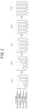
- the controller 7 Upon start of the charge control operation, the controller 7 defines, as demonstrated in Fig. 2 , levels of voltage developed at the batteries 41 of the n battery modules 4 (hereinafter also referred to as levels of voltage developed at the battery modules 4) as a first charge switching threshold, a second charge switching threshold, a ( n -1) th charge switching threshold, and an n th charge switching threshold in order from low to high level.
- the battery modules 4 in response to the above charge switching thresholds, will be referred to as a first battery module 4, a second battery module 4, a ( n -1) th battery module 4, and an n th battery module 4, respectively, and are denoted by "1", “2", “n- 1” , and "n” on graphs illustrated in Fig. 2 .
- the controller 7, as demonstrated in Fig. 2(a) starts firstly charging the first battery module 4 (i.e., the battery module 4(m)) in which level of voltage at the battery 41 is the lowest in the battery modules.
- the controller 7 turns on the second switch 42 and the third switch 8 of the second battery module 4 (i.e., the battery module 4(m+1)) to start secondly charging the second battery module 4. This causes both the first and second battery modules 4 to be being charged.
- the controller 7 turns on the second switch 42 and the third switch 8 of the ( n -1) th battery module 4 (i.e., the battery module 4(m+1)) to start charging the ( n -1) th battery module 4. This causes the first and second battery modules 4 and the ( n -1) th battery module 4 to be being charged.
- the controller 7 turns on the second switch 42 and the third switch 8 of the n th battery module 4 (i.e., the battery module 4(m+1)) to start charging the n th battery module 4.
- This causes the first and second battery modules 4, the ( n- 1) th battery module 4, and the n th battery module 4 to be all being charged. Subsequently, all the battery modules 4 are, as demonstrated in Fig. 2(e) , fully charged.
- the charging operations shown in Fig. 3 are mainly executed by the controller 7 and the battery management device 43.
- the charging control program is cyclically performed at a given interval.
- step S1 the controller 7 determines whether a level of voltage generated by the power generating unit 2 is higher than or equal to a first voltage level.
- the first voltage level is determined to be a level of generated voltage which is permitted to charge the battery modules 4 and at least higher than a level of voltage developed at the fully charged battery module 4.
- the first voltage level is experimentally derived and stored in a ROM of the controller 7, in advance.
- step S1 If a NO answer is obtained in step S1 meaning that the level of voltage generated by the power generating unit 2 is lower than the first voltage level, then the routine proceeds to step S12. Alternatively, if a YES answer is obtained in step S1 meaning that the level of voltage generated by the power generating unit 2 is higher than or equal to the first voltage level, then the routine proceeds to step S2 wherein the controller 7 turns on and places the first switch 6 in the electrical generation on-state.
- the first switch 6 is to be placed in the electrical generation on-state, when electrical power is not yet supplied to the controller 7, for example, before the charge/discharge control system 1 is initially started.
- This enables the power generating unit 2 to output the generated electrical power to the charge/discharge control system 1, thereby starting the charge/discharge control system 1 without use of an external power supply even when the charge/discharge control system 1 is rendered OFF. That is, in step S2, in a case where the first switch 6 is already placed in the electrical generation on-state, the controller 7 maintains the electrical generation on-state.
- step S3 the routine proceeds to step S3 wherein, the controller 7 turns on all the third switches 8 for all the battery modules 4, and the battery management devices 43 obtain the level of voltage developed at each of the battery modules 4.
- the operation in step S3 is made only when the charge/discharge control system 1 is initially started. In other words, e.g., in each of the repeated charging operations after initial start-up, step S3 may be omitted.
- step S3 is performed to obtain the levels of voltage at all the battery modules 4.
- the levels of voltage at the batteries 41 are derived during operation of the battery management devices 43 or at a time when the battery management devices 43 are turned off, and then stored in a RAM of the controller 7.
- the controller 7 may obtain the level of voltage thereof by estimating an amount of self-discharge thereof and correcting the stored level of voltage as to said battery module(s) 4. In addition, when actually obtaining the level of voltage at each of the battery modules 4 in a subsequent charging cycle, the controller 7 may compare the actually obtained level of voltage with the corresponding corrected level of voltage to alter the correction factor or determine that the corresponding battery module 4 is aged or deteriorated if the actually obtained level of voltage is lower than the corresponding corrected level of voltage by a predetermined value or more.
- step S4 the controller 7 defines the levels of voltage at the battery modules 4 as the first charge switching threshold, the second charge switching threshold, ... the ( n -1) th charge switching threshold, and the n th charge switching threshold in order from low to high level and stores them in the RAM thereof. Note that "n” indicates the number of the battery modules 4.
- the variable m is used in step S7 or following steps which will be described later.
- the routine proceeds to step S6 wherein the controller 7 determines whether there is the battery module(s) 4 whose level of voltage is lower than a fully charged reference level.
- the fully charged reference level is a level of voltage at which the battery 41 of each of the battery modules 4 is determined to be fully charged.
- step S6 If a NO answer is obtained in step S6 meaning that there are no battery modules 4 whose levels of voltage are lower than the fully charged reference level, the controller 7 concludes that the levels of voltages at the battery modules 4 are all higher than or equal to the fully charged reference level, causing the routine to proceed to step S12.
- step S12 the controller 7 determines whether a level of voltage generated by the power generating unit 2 is higher than or equal to a second voltage level.
- the second voltage level is lower than the above described first voltage level and higher than a level of voltage at the fully charged battery module 4.
- step S12 If a YES answer is obtained in step S12 meaning that the level of voltage generated by the power generating unit 2 is higher than or equal to the second voltage level, then the routine terminates. Afterwards, the charge control operation is started again in a subsequent charging cycle.
- the charge/discharge control system 1 executes a floating charge and maintains it.
- the floating charge is a mode of operation of the charge/discharge control system 1 to apply only charging voltage to the batteries 41 to charge the batteries 41 without charging current flowing therethrough, thereby increasing the service life of the batteries 41.
- step S12 if a NO answer is obtained in step S12 meaning that that the level of voltage generated by the power generating unit 2 is lower than the second voltage level, then the routine proceeds to step S13 wherein the controller 7 turns off the first switch 6 (i.e., the controller 7 places the first switch 6 in the off-state). The routine then terminates.
- step S13 The reasons why the first switch 6 is turned off in step S13 are because when the generated voltage is lower than the second voltage level, it is difficult to output a charging voltage required for the floating charge to continue to be performed, and when the generated voltage is lower than the fully charged reference level, it may cause the current to flow back to the power generating unit 2, thereby leading to a malfunction of the power generating unit 2. Additionally, in order to deter undesirable discharging of the batteries 41, the first switch 6 is turned off.
- the operation in step S8 may be omitted in each charging cycle following the initial charging cycle of the charge control operation, otherwise (i.e., if these third switches 8 to be turned off in step S8 are kept on) it will undesirably consume the electrical energy.
- step S9 it is determined whether, level of voltage at the battery module(s) 4 during charging is higher than or equal to the ( m+1 ) th charge switching threshold, i.e., said level of voltage reaches this charge switching threshold.
- the battery module(s) 4 during charging corresponds to one(s) of which the second switch 42 and the third switch 8 are turned on in step S7. This causes said battery module(s) 4 during charging to continue to be charged until the level of voltage thereof reaches the (m+1 ) th charge switching threshold (i.e., the charge switching threshold corresponding to the battery module 4 of which the level of voltage is the lowest among the remaining battery modules 4 except for said battery module(s) 4).
- step S9 If a NO answer is obtained in step S9 meaning that the level of voltage at the battery module(s) 4 during charging is lower than the ( m+1 ) th charge switching threshold, then the routine returns back to step S6.
- step S9 if a YES answer is obtained in step S9 meaning that the level of voltage at the battery module(s) 4 becomes higher than or equal to the ( m+1 ) th charge switching threshold, then the routine proceeds to step S10 wherein it is determined whether the variable m is smaller than the numeral n which indicates the total number of the battery modules 4 of the charge/discharge control system 1.
- step S10 If a NO answer is obtained in step S10 meaning that the variable m is not smaller than the numeral n, then the routine returns back to step S6.
- step S10 if a YES answer is obtained in step S10 meaning that the variable m is smaller than the numeral n, then the routine proceeds to step S11 wherein the controller 7 adds "1" to the variable m. The routine then returns back to step S6. This causes the battery modules 4 to be charged in order from low to high voltage.
- steps S6 to S9 and steps S10 and/or S11 are repeated, thereby causing one of the battery modules 4 which is the lowest in voltage developed thereat to firstly start to be charged and the remaining battery modules 4 to start, in sequence, to be charged in order from low to high voltage.
- This enables the levels of voltage at the battery modules 4 which are lower than the fully charged reference level to be equalized, preventing an undesirable high current from flowing through the battery modules 4.
- the charge/discharge control system 1 operates in the following way.
- the first battery module which is the lowest in voltage in the battery modules 4 firstly starts to be charged. Subsequently, when the level of voltage at the first battery module reaches the second charge switching threshold, the second battery module starts to be charged.
- the charge/discharge control system 1 turns on the second switch 42 and the third switch 8, thereby minimizing a variation in voltage between the battery modules 4 when electrically connected together. It is also possible to equalize the levels of voltage at the battery modules 4, preventing a high current from flowing through the battery modules 4.
- Fig. 4 shows, as an example, the battery modules 4a, 4b, and 4n for the sake of convenience.
- the controller 7 sets levels of voltage at the battery modules 4 as the first charge switching threshold, the second charge switching threshold, ... and the n th charge switching threshold in order from low to high, and stores them.
- the level of voltage at the battery module 4a is lower than that at the battery module 4b.
- the level of voltage at the battery module 4b is lower than that at the battery module 4n. Accordingly, the levels of voltage at the battery module 4a, the battery module 4b, and the battery module 4n at time t1 are defined as the first charge switching threshold, the second charge switching threshold, and the n th charge switching threshold, respectively.
- the second switch 42a and the third switch 8a of the battery module 4a are turned on. This starts charging the battery module 4a.
- the second switch 42b and the third switch 8b of the battery module 4b are turned on. This starts charging the battery module 4b.
- the second switch 42n and the third switch 8n of the battery module 4n are turned on. This starts charging the battery module 4n.
- the charge/discharge control system 1 enters the floating charge mode.
- the charge/discharge control system 1 places the first switch 6 in the off-state and the floating charge mode is terminated.
- the charge/discharge control system 1 turns on the second switch 42 and the third switch 8 of the ( m+ 1) th battery module 4(m+1) in the charging mode when a condition where the level of voltage at the m th battery module 4(m) which is being charged reaches the level of voltage at the ( m+ 1) th battery module 4(m+1) is met.
- the charge/discharge control system 1 in this embodiment therefore, works to turn on the second switch 42 and the third switch 8 at a time when the level of voltage at one of the battery modules 4 becomes close to that at another of the battery modules 4, thereby minimizing a variation in voltage between the battery modules 4 when electrically connected together.
- the charge/discharge control system 1 also works to equalize the levels of voltage at the battery modules 4, preventing a high current from flowing through the battery modules 4. This minimizes an imbalance in number of uses among the battery modules 4 and reduces an imbalance in degree of deterioration among the battery modules 4.
- the charge/discharge control system 1 places the first switch 6 in the electrical generation on-state.
- the charge/discharge control system 1 can prevent electrical current from flowing from the corresponding battery module(s) 4 back to the power generating unit 2, thereby preventing a malfunction of the power generating unit 2.
- the charge/discharge control system 1 places the first switch 6 in the off-state.
- the charge/discharge control system 1 therefore, avoids unwanted electrical connection of the power generating unit 2 with the battery modules 4 when the power generating unit 2, due to the generated voltage lower than the second voltage level, is not allowed to output a charging voltage required to maintain the floating charge mode.
- the charge/discharge control system 1 works to avoid flow of electrical current back to the power generating unit 2, which may result in a malfunction of the power generating unit 2 and prevents undesirable discharging of the batteries 41 from occurring.
- the charge/discharge control system 1 has the power generating unit 2 designed as an electrical generator working to generate electricity using renewable energy. This enables the charge/discharge control system 1 to be installed outdoors independently.
- the charge/discharge control system 1 is engineered for the electrical load 3 implemented by a light emitter, thereby enabling the charge/discharge control system 1 to be used for lights or electronic message boards installed outdoors independently.
Landscapes
- Engineering & Computer Science (AREA)
- Power Engineering (AREA)
- Transportation (AREA)
- Mechanical Engineering (AREA)
- Life Sciences & Earth Sciences (AREA)
- Sustainable Development (AREA)
- Sustainable Energy (AREA)
- Charge And Discharge Circuits For Batteries Or The Like (AREA)
- Secondary Cells (AREA)
Claims (5)
- Lade-/Entladesteuerungssystem (1) umfassend:eine Leistungserzeugungseinheit (2);eine elektrische Last (3);eine Mehrzahl von Batteriemodulen (4);einen ersten Verbindungspfad (5), mit dem die Batteriemodule (4) parallel zueinander verbunden sind;einen ersten Schalter (6), der zwischen dem ersten Verbindungsweg (5), der Leistungserzeugungseinheit (2) und der elektrischen Last (3) angeordnet ist und zwischen einem Einschaltzustand, in dem der erste Verbindungsweg (5) mit der Leistungserzeugungseinheit (2) oder der elektrischen Last (3) verbunden ist, und einem Ausschaltzustand, in dem der erste Verbindungsweg (5) von der Leistungserzeugungseinheit (2) und der elektrischen Last (3) getrennt ist, umschaltbar ist; undeine Steuerung (7), die mit elektrischer Leistung von der Leistungserzeugungseinheit (2) oder den Batteriemodulen (4) versorgt wird, wobeijedes der Batteriemodule (4) eine Batterie (41), einen zweiten Schalter (42), der zwischen einem Einschaltzustand, in dem die Batterie (41) mit dem ersten Verbindungspfad (5) verbunden ist, und einem Ausschaltzustand, in dem die Batterie (41) von dem ersten Verbindungspfad (5) getrennt ist, schaltbar ist, und eine Batteriesteuervorrichtung (43) umfasst, die einen Zustand der Batterie (41) und einen Schaltbetrieb des zweiten Schalters (42) steuert,ein dritter Schalter (8) zwischen jeder der Batteriesteuerungsvorrichtungen (43) und dem ersten Verbindungspfad (5) angeordnet ist, wobei der dritte Schalter (8) zwischen einem Einschaltzustand, in dem die Batteriesteuerungsvorrichtung (43) mit dem ersten Verbindungspfad (5) verbunden ist, und einem Ausschaltzustand, in dem die Batteriesteuerungsvorrichtung (43) von dem ersten Verbindungspfad (5) getrennt ist, umschaltbar ist,wobei die Steuerung (7) den Betrieb des ersten Schalters (6) und des dritten Schalters (8) steuert, undin einem Fall, in dem der erste Schalter (6) in den Ein-Zustand versetzt wird, in dem der erste Verbindungsweg (5) mit der Stromerzeugungseinheit (2) verbunden ist, um die Batteriemodule (4) aufzuladen, die Steuerung (7) alle dritten Schalter (8) aller Batteriemodule (4) ein schaltet, und die Batteriesteuerungsvorrichtungen (43) das Spannungsniveau, das an jedem der Batteriemodule (4) entwickelt wird, erhalten, wobei, wenn eines der Batteriemodule (4), dessen Batterie (41) das niedrigste Spannungsniveau der Batteriemodule (4) entwickelt, als m-tes Batteriemodul festgelegt wird, und wenn ein anderes der Batteriemodule (4), dessen Batterie (41) das zweitniedrigste Spannungsniveau der Batteriemodule (4) entwickelt, als (m+1)-tes Batteriemodul festgelegt wird; die Steuerung (7) alle dritten Schalter (8) mit Ausnahme des dritten Schalters (8) ausschaltet, der dem Batteriemodul (4) entspricht, in dem das an dessen Batterie (41) entwickelte Spannungsniveau niedriger oder gleich dem m-ten Ladeschaltschwellenwert ist; wobei die Steuerung (7) den zweiten Schalter (42) und den dritten Schalter (8) des (m+1)-ten Batteriemoduls einschaltet, wenn eine Bedingung erfüllt ist, bei der das Spannungsniveau am m-ten Batteriemodul während des Ladevorgangs, bei dem der zweite Schalter (42) und der dritte Schalter (8) jeweils im eingeschalteten Zustand sind, den Spannungspegel am (m+1)-ten Batteriemodul erreicht.
- Das Lade-/Entladesteuerungssystem (1) gemäß Anspruch 1, wobei, wenn ein von der Leistungserzeugungseinheit (2) erzeugtes Spannungsniveau höher oder gleich einem ersten Spannungspegel ist, der höher als das Spannungsniveau an jedem der Batteriemodule (4) ist, die Steuerung (7) den ersten Schalter (6) in den Ein-Zustand versetzt, in dem der erste Verbindungspfad (5) mit der Leistungserzeugungseinheit (2) verbunden ist.
- Das Lade-/Entladesteuerungssystem (1) gemäß Anspruch 2, wobei, wenn das Spannungsniveau an jedem der Batteriemodule (4) höher oder gleich einem vollständig geladenen Referenzniveau ist, bei dem festgestellt wird, dass die Batterie (41) jedes Batteriemoduls (4) vollständig geladen ist, und das von der Leistungserzeugungseinheit (2) erzeugte Spannungsniveau unter einem zweiten Spannungsniveau liegt, das niedriger ist als das erste Spannungsniveau, versetzt die Steuerung (7) den ersten Schalter (6) in den Aus-Zustand.
- Das Lade-/Entladesteuerungssystem (1) gemäß einem der Ansprüche 1 bis 3, wobei die Leistungserzeugungseinheit (2) ein Stromgenerator ist, der elektrischen Strom unter Verwendung erneuerbarer Energie erzeugt.
- Das Lade-/Entladesteuerungssystem (1) gemäß einem der Ansprüche 1 bis 4, wobei die elektrische Last (3) ein Lichtemitter ist.
Applications Claiming Priority (1)
| Application Number | Priority Date | Filing Date | Title |
|---|---|---|---|
| JP2020162619A JP7494685B2 (ja) | 2020-09-28 | 2020-09-28 | 充放電制御システム |
Publications (2)
| Publication Number | Publication Date |
|---|---|
| EP3974232A1 EP3974232A1 (de) | 2022-03-30 |
| EP3974232B1 true EP3974232B1 (de) | 2025-06-18 |
Family
ID=77897449
Family Applications (1)
| Application Number | Title | Priority Date | Filing Date |
|---|---|---|---|
| EP21197011.6A Active EP3974232B1 (de) | 2020-09-28 | 2021-09-16 | System zur ladungs-/entladungssteuerung |
Country Status (2)
| Country | Link |
|---|---|
| EP (1) | EP3974232B1 (de) |
| JP (1) | JP7494685B2 (de) |
Families Citing this family (1)
| Publication number | Priority date | Publication date | Assignee | Title |
|---|---|---|---|---|
| JP7292319B2 (ja) * | 2021-02-25 | 2023-06-16 | プライムプラネットエナジー&ソリューションズ株式会社 | 電池システムおよび制御方法 |
Family Cites Families (13)
| Publication number | Priority date | Publication date | Assignee | Title |
|---|---|---|---|---|
| JP2000324711A (ja) * | 1999-05-17 | 2000-11-24 | Canon Inc | 組み電池装置 |
| JP2010068558A (ja) | 2008-09-08 | 2010-03-25 | Nippon Telegr & Teleph Corp <Ntt> | 充電装置および充電方法 |
| JP2012090376A (ja) | 2010-10-15 | 2012-05-10 | Sanyo Electric Co Ltd | 電源システム |
| JP5527183B2 (ja) | 2010-12-01 | 2014-06-18 | 株式会社デンソー | 電池制御システム、充放電制御ecu |
| JP2014171369A (ja) | 2013-03-05 | 2014-09-18 | Denso Corp | 電力供給システム |
| JP6260192B2 (ja) * | 2013-10-21 | 2018-01-17 | 三菱自動車工業株式会社 | バッテリーパック |
| WO2015156210A1 (ja) | 2014-04-08 | 2015-10-15 | 株式会社豊田自動織機 | 電池監視装置 |
| JP2017103996A (ja) | 2015-12-04 | 2017-06-08 | 株式会社東芝 | 蓄電池システム、蓄電池ユニット、およびプログラム |
| JP2017220966A (ja) | 2016-06-03 | 2017-12-14 | 日立オートモティブシステムズ株式会社 | セルコントローラおよび電池監視装置 |
| US20190322193A1 (en) | 2018-04-19 | 2019-10-24 | Wayne State University | Battery module balancing system of a vehicle and method thereof |
| CN110417068A (zh) | 2018-04-27 | 2019-11-05 | 神讯电脑(昆山)有限公司 | 充电装置及其方法 |
| JP2019208309A (ja) | 2018-05-29 | 2019-12-05 | ダイムラー・アクチェンゲゼルシャフトDaimler AG | 電動車両の駆動制御装置 |
| US11239670B2 (en) * | 2018-09-16 | 2022-02-01 | Richard Landry Gray | Cell balancing battery module and electrical apparatus |
-
2020
- 2020-09-28 JP JP2020162619A patent/JP7494685B2/ja active Active
-
2021
- 2021-09-16 EP EP21197011.6A patent/EP3974232B1/de active Active
Also Published As
| Publication number | Publication date |
|---|---|
| EP3974232A1 (de) | 2022-03-30 |
| JP7494685B2 (ja) | 2024-06-04 |
| JP2022055173A (ja) | 2022-04-07 |
Similar Documents
| Publication | Publication Date | Title |
|---|---|---|
| US8674659B2 (en) | Charge control device and vehicle equipped with the same | |
| US8497661B2 (en) | Equalization device, equalization processing program, battery system, electric vehicle and equalization processing method | |
| US8493031B2 (en) | Equalization device, battery system and electric vehicle including the same, equalization processing program, and equalization processing method | |
| US9190861B2 (en) | Battery pack and method of controlling the same | |
| JP4523738B2 (ja) | 二次電池の残存容量制御方法および装置 | |
| US8054044B2 (en) | Apparatus and method for balancing of battery cell'S charge capacity | |
| CN102545317B (zh) | 用于引起电池温度上升的系统 | |
| KR102016752B1 (ko) | 배터리 팩 및 배터리 팩 제어방법 | |
| US9045047B2 (en) | Storage battery | |
| JP3931446B2 (ja) | 組電池の充電状態調整装置 | |
| KR101312263B1 (ko) | 운송 수단 및 그 제어 방법 | |
| CN102035226A (zh) | 车辆用电源装置及具备该装置的车辆、车辆用电源装置的容量均匀化方法 | |
| KR20130109038A (ko) | 배터리 팩 | |
| US9413037B2 (en) | Cell capacity adjusting device | |
| JP7494684B2 (ja) | 充放電制御システム | |
| JPH0997629A (ja) | 複数のリチウムイオン二次電池の充電方法 | |
| US20240047978A1 (en) | Power storage system | |
| JP2001314046A (ja) | 組電池の充電装置、充電方法、および電動車両 | |
| WO2013057821A1 (ja) | 蓄電装置管理システム | |
| EP3974232B1 (de) | System zur ladungs-/entladungssteuerung | |
| JP2011010448A (ja) | 制御ユニット | |
| CN116061670A (zh) | 电池系统和用于控制电池系统的方法 | |
| CN110816311B (zh) | 用于运行电池组系统的方法和电动车辆 | |
| JP2023035414A (ja) | ソーラー制御装置、方法、プログラム、及び車両 | |
| KR20220090206A (ko) | 다이오드를 이용한 배터리 이상 방지 장치 및 방법 |
Legal Events
| Date | Code | Title | Description |
|---|---|---|---|
| PUAI | Public reference made under article 153(3) epc to a published international application that has entered the european phase |
Free format text: ORIGINAL CODE: 0009012 |
|
| STAA | Information on the status of an ep patent application or granted ep patent |
Free format text: STATUS: REQUEST FOR EXAMINATION WAS MADE |
|
| 17P | Request for examination filed |
Effective date: 20210916 |
|
| AK | Designated contracting states |
Kind code of ref document: A1 Designated state(s): AL AT BE BG CH CY CZ DE DK EE ES FI FR GB GR HR HU IE IS IT LI LT LU LV MC MK MT NL NO PL PT RO RS SE SI SK SM TR |
|
| GRAP | Despatch of communication of intention to grant a patent |
Free format text: ORIGINAL CODE: EPIDOSNIGR1 |
|
| STAA | Information on the status of an ep patent application or granted ep patent |
Free format text: STATUS: GRANT OF PATENT IS INTENDED |
|
| INTG | Intention to grant announced |
Effective date: 20241216 |
|
| GRAS | Grant fee paid |
Free format text: ORIGINAL CODE: EPIDOSNIGR3 |
|
| GRAA | (expected) grant |
Free format text: ORIGINAL CODE: 0009210 |
|
| STAA | Information on the status of an ep patent application or granted ep patent |
Free format text: STATUS: THE PATENT HAS BEEN GRANTED |
|
| RIN1 | Information on inventor provided before grant (corrected) |
Inventor name: OSANAI, HIROKI Inventor name: MITSUOKA, SHIGEHI |
|
| AK | Designated contracting states |
Kind code of ref document: B1 Designated state(s): AL AT BE BG CH CY CZ DE DK EE ES FI FR GB GR HR HU IE IS IT LI LT LU LV MC MK MT NL NO PL PT RO RS SE SI SK SM TR |
|
| REG | Reference to a national code |
Ref country code: GB Ref legal event code: FG4D |
|
| REG | Reference to a national code |
Ref country code: CH Ref legal event code: EP |
|
| REG | Reference to a national code |
Ref country code: DE Ref legal event code: R096 Ref document number: 602021032369 Country of ref document: DE |
|
| REG | Reference to a national code |
Ref country code: CH Ref legal event code: EP |
|
| REG | Reference to a national code |
Ref country code: IE Ref legal event code: FG4D |
|
| PG25 | Lapsed in a contracting state [announced via postgrant information from national office to epo] |
Ref country code: FI Free format text: LAPSE BECAUSE OF FAILURE TO SUBMIT A TRANSLATION OF THE DESCRIPTION OR TO PAY THE FEE WITHIN THE PRESCRIBED TIME-LIMIT Effective date: 20250618 |
|
| PGFP | Annual fee paid to national office [announced via postgrant information from national office to epo] |
Ref country code: DE Payment date: 20250918 Year of fee payment: 5 |
|
| REG | Reference to a national code |
Ref country code: LT Ref legal event code: MG9D |
|
| PG25 | Lapsed in a contracting state [announced via postgrant information from national office to epo] |
Ref country code: GR Free format text: LAPSE BECAUSE OF FAILURE TO SUBMIT A TRANSLATION OF THE DESCRIPTION OR TO PAY THE FEE WITHIN THE PRESCRIBED TIME-LIMIT Effective date: 20250919 Ref country code: NO Free format text: LAPSE BECAUSE OF FAILURE TO SUBMIT A TRANSLATION OF THE DESCRIPTION OR TO PAY THE FEE WITHIN THE PRESCRIBED TIME-LIMIT Effective date: 20250918 |
|
| PG25 | Lapsed in a contracting state [announced via postgrant information from national office to epo] |
Ref country code: BG Free format text: LAPSE BECAUSE OF FAILURE TO SUBMIT A TRANSLATION OF THE DESCRIPTION OR TO PAY THE FEE WITHIN THE PRESCRIBED TIME-LIMIT Effective date: 20250618 |
|
| PG25 | Lapsed in a contracting state [announced via postgrant information from national office to epo] |
Ref country code: HR Free format text: LAPSE BECAUSE OF FAILURE TO SUBMIT A TRANSLATION OF THE DESCRIPTION OR TO PAY THE FEE WITHIN THE PRESCRIBED TIME-LIMIT Effective date: 20250618 |
|
| PGFP | Annual fee paid to national office [announced via postgrant information from national office to epo] |
Ref country code: FR Payment date: 20250924 Year of fee payment: 5 Ref country code: AT Payment date: 20251020 Year of fee payment: 5 |
|
| PG25 | Lapsed in a contracting state [announced via postgrant information from national office to epo] |
Ref country code: RS Free format text: LAPSE BECAUSE OF FAILURE TO SUBMIT A TRANSLATION OF THE DESCRIPTION OR TO PAY THE FEE WITHIN THE PRESCRIBED TIME-LIMIT Effective date: 20250918 |
|
| REG | Reference to a national code |
Ref country code: NL Ref legal event code: MP Effective date: 20250618 |
|
| PG25 | Lapsed in a contracting state [announced via postgrant information from national office to epo] |
Ref country code: LV Free format text: LAPSE BECAUSE OF FAILURE TO SUBMIT A TRANSLATION OF THE DESCRIPTION OR TO PAY THE FEE WITHIN THE PRESCRIBED TIME-LIMIT Effective date: 20250618 |
|
| PG25 | Lapsed in a contracting state [announced via postgrant information from national office to epo] |
Ref country code: NL Free format text: LAPSE BECAUSE OF FAILURE TO SUBMIT A TRANSLATION OF THE DESCRIPTION OR TO PAY THE FEE WITHIN THE PRESCRIBED TIME-LIMIT Effective date: 20250618 |
|
| PG25 | Lapsed in a contracting state [announced via postgrant information from national office to epo] |
Ref country code: PT Free format text: LAPSE BECAUSE OF FAILURE TO SUBMIT A TRANSLATION OF THE DESCRIPTION OR TO PAY THE FEE WITHIN THE PRESCRIBED TIME-LIMIT Effective date: 20251020 |
|
| REG | Reference to a national code |
Ref country code: AT Ref legal event code: MK05 Ref document number: 1803904 Country of ref document: AT Kind code of ref document: T Effective date: 20250618 |
|
| PG25 | Lapsed in a contracting state [announced via postgrant information from national office to epo] |
Ref country code: IS Free format text: LAPSE BECAUSE OF FAILURE TO SUBMIT A TRANSLATION OF THE DESCRIPTION OR TO PAY THE FEE WITHIN THE PRESCRIBED TIME-LIMIT Effective date: 20251018 |
|
| PG25 | Lapsed in a contracting state [announced via postgrant information from national office to epo] |
Ref country code: AT Free format text: LAPSE BECAUSE OF FAILURE TO SUBMIT A TRANSLATION OF THE DESCRIPTION OR TO PAY THE FEE WITHIN THE PRESCRIBED TIME-LIMIT Effective date: 20250618 Ref country code: SM Free format text: LAPSE BECAUSE OF FAILURE TO SUBMIT A TRANSLATION OF THE DESCRIPTION OR TO PAY THE FEE WITHIN THE PRESCRIBED TIME-LIMIT Effective date: 20250618 |
|
| PG25 | Lapsed in a contracting state [announced via postgrant information from national office to epo] |
Ref country code: CZ Free format text: LAPSE BECAUSE OF FAILURE TO SUBMIT A TRANSLATION OF THE DESCRIPTION OR TO PAY THE FEE WITHIN THE PRESCRIBED TIME-LIMIT Effective date: 20250618 |
|
| PG25 | Lapsed in a contracting state [announced via postgrant information from national office to epo] |
Ref country code: PL Free format text: LAPSE BECAUSE OF FAILURE TO SUBMIT A TRANSLATION OF THE DESCRIPTION OR TO PAY THE FEE WITHIN THE PRESCRIBED TIME-LIMIT Effective date: 20250618 |
|
| PG25 | Lapsed in a contracting state [announced via postgrant information from national office to epo] |
Ref country code: EE Free format text: LAPSE BECAUSE OF FAILURE TO SUBMIT A TRANSLATION OF THE DESCRIPTION OR TO PAY THE FEE WITHIN THE PRESCRIBED TIME-LIMIT Effective date: 20250618 |
|
| PG25 | Lapsed in a contracting state [announced via postgrant information from national office to epo] |
Ref country code: RO Free format text: LAPSE BECAUSE OF FAILURE TO SUBMIT A TRANSLATION OF THE DESCRIPTION OR TO PAY THE FEE WITHIN THE PRESCRIBED TIME-LIMIT Effective date: 20250618 Ref country code: SK Free format text: LAPSE BECAUSE OF FAILURE TO SUBMIT A TRANSLATION OF THE DESCRIPTION OR TO PAY THE FEE WITHIN THE PRESCRIBED TIME-LIMIT Effective date: 20250618 |
|
| PG25 | Lapsed in a contracting state [announced via postgrant information from national office to epo] |
Ref country code: ES Free format text: LAPSE BECAUSE OF FAILURE TO SUBMIT A TRANSLATION OF THE DESCRIPTION OR TO PAY THE FEE WITHIN THE PRESCRIBED TIME-LIMIT Effective date: 20250618 |
|
| REG | Reference to a national code |
Ref country code: DE Ref legal event code: R097 Ref document number: 602021032369 Country of ref document: DE |
|
| PG25 | Lapsed in a contracting state [announced via postgrant information from national office to epo] |
Ref country code: DK Free format text: LAPSE BECAUSE OF FAILURE TO SUBMIT A TRANSLATION OF THE DESCRIPTION OR TO PAY THE FEE WITHIN THE PRESCRIBED TIME-LIMIT Effective date: 20250618 |
|
| PG25 | Lapsed in a contracting state [announced via postgrant information from national office to epo] |
Ref country code: IT Free format text: LAPSE BECAUSE OF FAILURE TO SUBMIT A TRANSLATION OF THE DESCRIPTION OR TO PAY THE FEE WITHIN THE PRESCRIBED TIME-LIMIT Effective date: 20250618 |
|
| PLBE | No opposition filed within time limit |
Free format text: ORIGINAL CODE: 0009261 |
|
| STAA | Information on the status of an ep patent application or granted ep patent |
Free format text: STATUS: NO OPPOSITION FILED WITHIN TIME LIMIT |
|
| REG | Reference to a national code |
Ref country code: CH Ref legal event code: L10 Free format text: ST27 STATUS EVENT CODE: U-0-0-L10-L00 (AS PROVIDED BY THE NATIONAL OFFICE) Effective date: 20260430 |