EP3974363A1 - Transportvorrichtung für eine kabelrolle mit einem richtrohr - Google Patents
Transportvorrichtung für eine kabelrolle mit einem richtrohr Download PDFInfo
- Publication number
- EP3974363A1 EP3974363A1 EP21306328.2A EP21306328A EP3974363A1 EP 3974363 A1 EP3974363 A1 EP 3974363A1 EP 21306328 A EP21306328 A EP 21306328A EP 3974363 A1 EP3974363 A1 EP 3974363A1
- Authority
- EP
- European Patent Office
- Prior art keywords
- cable
- transport device
- tube
- straightening
- casing
- Prior art date
- Legal status (The legal status is an assumption and is not a legal conclusion. Google has not performed a legal analysis and makes no representation as to the accuracy of the status listed.)
- Granted
Links
Images



Classifications
-
- B—PERFORMING OPERATIONS; TRANSPORTING
- B65—CONVEYING; PACKING; STORING; HANDLING THIN OR FILAMENTARY MATERIAL
- B65H—HANDLING THIN OR FILAMENTARY MATERIAL, e.g. SHEETS, WEBS, CABLES
- B65H49/00—Unwinding or paying-out filamentary material; Supporting, storing or transporting packages from which filamentary material is to be withdrawn or paid-out
- B65H49/02—Methods or apparatus in which packages do not rotate
- B65H49/04—Package-supporting devices
- B65H49/06—Package-supporting devices for a single operative package
- B65H49/08—Package-supporting devices for a single operative package enclosing the package
-
- B—PERFORMING OPERATIONS; TRANSPORTING
- B65—CONVEYING; PACKING; STORING; HANDLING THIN OR FILAMENTARY MATERIAL
- B65H—HANDLING THIN OR FILAMENTARY MATERIAL, e.g. SHEETS, WEBS, CABLES
- B65H49/00—Unwinding or paying-out filamentary material; Supporting, storing or transporting packages from which filamentary material is to be withdrawn or paid-out
- B65H49/38—Skips, cages, racks, or containers, adapted solely for the transport or storage of bobbins, cops, or the like
-
- B—PERFORMING OPERATIONS; TRANSPORTING
- B65—CONVEYING; PACKING; STORING; HANDLING THIN OR FILAMENTARY MATERIAL
- B65H—HANDLING THIN OR FILAMENTARY MATERIAL, e.g. SHEETS, WEBS, CABLES
- B65H57/00—Guides for filamentary materials; Supports therefor
- B65H57/12—Tubes
-
- B—PERFORMING OPERATIONS; TRANSPORTING
- B65—CONVEYING; PACKING; STORING; HANDLING THIN OR FILAMENTARY MATERIAL
- B65H—HANDLING THIN OR FILAMENTARY MATERIAL, e.g. SHEETS, WEBS, CABLES
- B65H57/00—Guides for filamentary materials; Supports therefor
- B65H57/18—Guides for filamentary materials; Supports therefor mounted to facilitate unwinding of material from packages
-
- B—PERFORMING OPERATIONS; TRANSPORTING
- B65—CONVEYING; PACKING; STORING; HANDLING THIN OR FILAMENTARY MATERIAL
- B65D—CONTAINERS FOR STORAGE OR TRANSPORT OF ARTICLES OR MATERIALS, e.g. BAGS, BARRELS, BOTTLES, BOXES, CANS, CARTONS, CRATES, DRUMS, JARS, TANKS, HOPPERS, FORWARDING CONTAINERS; ACCESSORIES, CLOSURES, OR FITTINGS THEREFOR; PACKAGING ELEMENTS; PACKAGES
- B65D85/00—Containers, packaging elements or packages, specially adapted for particular articles or materials
- B65D85/02—Containers, packaging elements or packages, specially adapted for particular articles or materials for annular articles
- B65D85/04—Containers, packaging elements or packages, specially adapted for particular articles or materials for annular articles for coils of wire, rope or hose
Definitions
- the present invention relates to the field of cable transport and unwinding, in particular in the form of cable coils.
- the present invention relates more specifically to a transport device for a coil of cable with a straightening tube.
- the cable For packaging and transporting a cable, it is usual to wrap the cable around itself so as to form a cable ring.
- the cable can be wound in the form of a ring and covered with a film, for example plastic, as soon as it is marketed to the end customer.
- the cable coil can be formed by the end user for transport and future use when the cable is sold "in bulk", i.e. the customer has the option of purchasing only a portion of the length total cable.
- This packaging can take the form of a transportable cover in which a cavity is adapted to receive a coil of cable.
- An orifice is generally formed through a wall of the packaging so as to be able to pass the cable out of the packaging.
- the package is generally held to a support or by a user and the cable is pulled through the hole for its use.
- the arrangement of the cable in the form of a crown causes a “spiral effect” of the cable, ie the cable turns around itself and forms tendrils when it is unwound. Indeed, the cable being wound around itself, the unwinding of the cable causes it to undergo a torsion which results in spins once unwound. This effect of spirals can be very troublesome for the installation of the cable.
- the cable can in fact get stuck or rub against many obstacles when it is drawn inside a sheath. The installation of the cable can thus be lengthened significantly and make the pulling difficult for the user.
- the use of a straightening tube for the unwinding of the cable makes it possible to straighten the cable by forming a point of support allowing the spirals of the cable at the output of the device to be undone.
- the cable at the output of the straightening tube has a much lower number of spins or no longer has any depending on the dimensions of the straightening tube and the unwinding force applied by the user.
- the straightening tube makes it possible to give a direction of unwinding to the cable and to maintain it in this direction at the outlet of the reception cavity.
- the pulling of the cable is greatly facilitated because the cable is straightened and does not shift according to the spirals during the pulling.
- the unwinding is also more precise because the orientation of the straightening tube freezes the direction of unwinding. This can thus allow a single user to pull a cable or reduce the handling required.
- the rectifier tube therefore saves significant time and/or personnel for unwinding the cable.
- the rectifier tube preferably extends out of the receiving cavity from said wall of the casing. Preferably, at least 80% of the length of the rectifier tube is placed outside the reception cavity. Therefore, the rectifier tube is disposed wholly or partly outside the receiving cavity. This makes it possible in particular to facilitate the installation or removal of this rectifier tube when it is removable. This also allows the rectifier tube to have a length independent of the dimensions of the receiving cavity. In fact, when it is placed inside the reception cavity, the rectifier tube can protrude from the wall only by a maximum of a length equivalent to the depth of the reception cavity. The straightening function is therefore limited in the latter case.
- the rectifier tube is preferably of circular cross-section.
- the rectifier tube can be of any cross-sectional shape, e.g. square section.
- the straightening tube is configured to be removably fixed to said wall.
- the user can thus remove the rectifier tube from the casing.
- This can have the advantage of reducing the size of the device, in particular during transport.
- This has the further advantage of allowing the user to change the rectifier tube, for example to install another rectifier tube having dimensions adapted to the type of cable in the casing or else another accessory.
- the outlet orifice is arranged so as to open out at the level of a central portion of the reception cavity.
- the receiving cavity is of circular cross-section.
- the receiving cavity thus adapts to the geometry of the cable ring to improve its retention inside the casing.
- the casing can also be of circular transverse shape to limit the size of the transport device.
- the rectifier tube is elongated, the length of the rectifier tube being at least greater than three times the maximum transverse dimension of the rectifier tube.
- the rectifier tube is elongated, the length of the rectifier tube being equal to or greater than 50 mm.
- the latter further comprises a guide of flared shape arranged at the level of a proximal end of the straightening tube when the straightening tube is arranged at the level of the outlet orifice.
- the guide makes it possible to limit the deformation of the cable at the outlet orifice of the casing as well as the friction between the wall of the outlet orifice and the cable. This facilitates the exit of the cable, in particular by reducing the force necessary for the exit of the cable during the unwinding of the latter.
- the guide can be a piece added to the level of the outlet orifice or formed by the rectifier tube itself.
- the guide forms a conduit 37 for guiding the cable, the cross-section of which decreases substantially in the direction of the outlet orifice.
- the guide duct 37 can be in the shape of a cone or have a curvature converging towards the outlet orifice.
- the latter further comprises an anchoring member fixed to the casing and configured to make it possible to anchor the casing to a support point during the unwinding of a cable.
- the anchoring member allows a single user to unwind the cable placed inside the casing. Once the envelope is anchored to a support, for example a door handle, the user only has to pull on the cable to unroll it.
- This anchoring member can be in the form of a hook attached to the casing or an orifice formed by the casing. Alternatively or in combination, the anchoring member can be a carrying handle secured to the casing.
- the cable outlet orifice is formed at the level of a front wall of the casing, said casing further comprising a bottom wall opposite the front wall with respect to the cavity reception, an additional cable outlet orifice out of the reception cavity being formed in said bottom wall.
- this additional orifice may differ from those of the outlet orifice, for example to be adapted to cables of different dimensions.
- the additional orifice can also be configured to receive the rectifier tube and/or the guide.
- This additional orifice can be used to unroll another end of the cable than that passing through the outlet orifice.
- the user thus simultaneously benefits from two outlet orifices which may be of different sizes and/or allowing different rectifier tube configurations (eg two rectifier tubes of different sizes or a single rectifier tube mounted on one of the outlet orifices) .
- the invention also relates to a transport set comprising a transport device as described above and at least one other straightening tube, in which the straightening tubes have a length and/or a cross-section different from one another.
- a transport device 10 for a coil of cable is presented.
- This transport device 10 forms a cover for transporting and unwinding a cable wound around itself in the form of a crown.
- the transport device 10 is preferably reusable so that the coil of cable can be inserted or extracted from the transport device 10.
- the transport device 10 comprises a casing 12 forming a cavity 14 for receiving a coil of cable 16, more particularly visible in figure 2 .
- the casing 12 is of circular section so as to present a minimal bulk while accommodating a cable ring. More particularly, the casing has the shape of a flat cylinder, ie the thickness of which is less than the diameter. Alternatively, the casing 12 can be of any shape whose dimensions make it possible to accommodate a ring of cable 16.
- the envelope 12 is preferably made of a flexible material.
- the envelope 12 is preferably made of a wear-resistant material, such as for example a woven fabric of PVC or polyester.
- the reception cavity 14 can be directly formed by the walls of the casing 12 or by walls internal to the casing 12 distinct from the external walls of the casing 12. In other words, the reception cavity 14 can correspond to the entire interior space defined by the envelope 12 or only a portion of this space. To obtain minimum bulk and a more economical transport device, it is preferable for the receiving cavity 14 to be formed by the walls of the casing 12 itself.
- the reception cavity 14 is of circular section so as to present a minimal bulk while accommodating a cable ring. More particularly, the envelope has the shape of a flat cylinder, i.e. the thickness of which is less than the diameter. Alternatively, the receiving cavity 14 can be of any shape whose dimensions and geometry make it possible to accommodate a cable ring 16. Thus, the receiving cavity preferably has a minimum thickness of 5 cm and a minimum transverse dimensions ( or minimum diameter, if applicable) of 30cm. According to one example, the receiving cavity 14 has a thickness of 15cm and a diameter of 50cm to adapt to a coil of cable having a thickness of about 10cm and a diameter of about 40cm.
- the casing 12 comprises a front wall 18 and a bottom wall 20 arranged facing the front wall 18 and opposite the latter with respect to the receiving cavity.
- the front 18 and bottom 20 walls are respectively intended to face opposite sides of a cable ring 16 arranged inside the reception cavity 14.
- the envelope 12 also includes a side wall 22 connecting the front 18 and bottom 20 walls to close the receiving cavity 14.
- the side wall 18 preferably forms a side strip connecting the edges of each of the front 18 and bottom 20 walls. .
- the casing 12 comprises an opening 24 allowing access to the reception cavity 14.
- This opening 24 is configured to allow the insertion of a coil of cable inside this reception cavity 14.
- the opening 24 is preferably made on the side wall 22.
- the opening 24 preferably extends over at least 50% of the length of the side wall 22 so as to facilitate the insertion of the cable coil 16 inside the the receiving cavity 14.
- the opening 24 can thus be wide open by moving the front 18 and bottom 20 walls away from each other. Even more preferably, the opening 24 extends over at least 70% of the length of the side wall 22 so as to allow an even greater distance from the front walls 18, or even to allow the flattening of the front walls 18 and bottom 20 to completely open the envelope 12.
- the opening 24 comprises a closure system 19 which can be for example a zipper.
- the transport device 10 also includes a transport handle 26 to make it easier to grip the transport device 10.
- the transport handle 26 can also serve as an anchor member for the casing to allow the cable to be unwound.
- the casing 12 also includes a cable exit orifice 28 out of the receiving cavity 14. The crown cable is thus unwound through this exit orifice 28.
- the outlet orifice 28 is preferably formed so as to emerge at the level of a central portion of the receiving cavity 14.
- the outlet orifice 28 is formed through the front wall 18 or the wall bottom 20.
- the outlet orifice 28 provides access to the central part of the cable crown when the latter is disposed inside the receiving cavity 14.
- the orifice of outlet 28 is arranged in the center of the front wall 18.
- the casing 12 and therefore the front wall 18 are circular in shape, the casing 12 extends around a main axis A.
- the outlet orifice 28 is arranged at the level of this main axis A and coincides with the axis of the crown around which the cable is wound.
- the transport device 10 further comprises a straightening tube 30 visible in picture 3 .
- the rectifier tube 30 is configured to be placed at the outlet orifice 28 and protrudes from the wall of the casing 12, here the front wall 18.
- the straightening tube 30 comprises a proximal end 32 intended to be placed at the level of the outlet orifice 28 and a distal end 34 by which the cable is passed out of the transport device 10.
- a straightening conduit 35 extends between these proximal 32 and distal 34 ends.
- the proximal end 32 of the straightening tube 30 is arranged facing the outlet orifice 28 to cause the straightening tube 30 to communicate with the receiving cavity 14 through the outlet orifice 28. It is thus possible to unroll the cable out of the receiving cavity 14 through the outlet orifice 28 then through the straightening tube 30.
- the straightening tube 30 makes it possible to form a fulcrum making it possible to straighten the cable under a cable tension force. This straightening makes it possible to reduce or avoid the spiral effect generated by the unwinding of the cable as well as to limit the offset of the cable during unwinding.
- the rectifier tube 30 is preferably configured to be secured to the outlet orifice 28.
- the proximal end 32 of the rectifier tube 30 is configured to be secured or anchored at the level of the outlet orifice 28.
- This securing can be achieved by means of an attached locking device 31 making it possible to hold the straightening tube 30 opposite the outlet orifice 28.
- This locking device can be a sleeve configured to be inserted inside the exit port 28.
- the straightening tube 30 is then inserted inside the sleeve.
- a nut or clamp cooperating with the sleeve is then used to compress the straightening tube 30 and hold it in position.
- proximal end 32 may form at least a portion of locking means to the outlet port 28.
- proximal end 32 may include a shape configured to anchor to a shape, notch, or orifice formed at exit port 28.
- Straightening tube 30, for example may anchor to the outlet 28 by means of a bayonet system or a system of deformable tongues.
- the dimensions of the straightening tube 30 and of the outlet orifice 28 can be configured to allow a tight fit of the proximal end 32 in the outlet orifice 28.
- the straightening tube 30 can thus be manually inserted by force into the outlet orifice 28 for its establishment.
- the removal of the straightening tube can be done in the opposite way by manually pulling the straightening tube 30 in the opposite direction. This last alternative makes it easier to attach the rectifier tube 30 to the outlet orifice 28 and constitutes a more economical solution because the parts are simpler.
- the rectifier tube 30 is preferably of circular section so as to form a straight cylindrical tube.
- the cylindrical shape of the straightening conduit 35 internal to the straightening tube 30 thus makes it possible to limit the friction of the cable with the straightening tube 30 and therefore to facilitate the unwinding of the cable by the user.
- the straightening tube 30 can be of any shape allowing the cable to slide from the proximal end 32 towards the distal end 34.
- the straightening tube 30 can be of any elongated shape.
- the length of the rectifier tube 30 is preferably at least greater than three times the maximum transverse dimension of the rectifier tube 30.
- maximum transverse dimensions is meant the maximum transverse dimension of the rectifier conduit 35 internal to the rectifier tube 30.
- the ratio between the length of the rectifier tube 30 and its internal diameter is equal to or greater than 3.
- the length of the rectifier tube 30 is at least greater than five times the maximum transverse dimension of the rectifier tube 30 so as to make the straightening even more effective.
- the length of the rectifier tube 30 is preferably equal to or greater than 50mm.
- the maximum transverse dimension of the rectifier tube 30 is preferably equal to or greater than 10mm.
- the straightening tube 30 is preferably removable with respect to the outlet orifice 28.
- the insert device, the outlet orifice 28 and/or the straightening tube 30 are therefore configured to allow the straightening tube 30 to be removed from the outlet port 28, preferably manually. It is thus possible to reduce the size of the transport device 10 by removing the rectifier tube 30 and only putting it in place when the cable must be unwound. This removability also allows more flexibility to the user in the use of the transport device 10.
- the transport device 10 is part of a transport set also comprising a plurality of rectifier tubes 30 having a length and/or a cross-section different from each other.
- the transport device 30 may also comprise a guide 36 of flared shape arranged at the level of the outlet orifice 28.
- the guide 36 is arranged upstream of the rectifier tube 30 so as to receive a portion of cable before the rectifier tube in the direction of cable unwinding.
- This guide 36 makes it possible to limit the deformation of the cable at the level of the outlet orifice 28 as well as the friction between the wall of the outlet orifice 28 and the cable. This facilitates the exit of the cable, in particular by reducing the force necessary for the exit of the cable during the unwinding of the latter.
- the guide 36 can be a piece added to the level of the outlet orifice 28 or formed by the rectifier tube 30 itself.
- the guide 36 forms a guide duct 37 of the cable, the cross-section of which decreases substantially in the direction of the outlet orifice 28.
- the guide duct 37 can be in the shape of a cone or have a curvature converging towards the orifice. output 28.
- the bottom wall 20 may also include an additional orifice 29 for the cable to exit from the reception cavity 14, as seen in figure 2 .
- This additional orifice can for example be used to unwind another end of the cable than that passing through the outlet orifice 28.
- the dimensions of this additional orifice 29 may differ from those of the outlet orifice 28, for example to be adapted to cables of different sizes. The diameter of the additional orifice 29 can thus be different from that of the outlet orifice 28.
- the additional orifice 29 can also be configured to receive the rectifier tube 30 and/or the guide 36.
- the additional orifice 29 can be configured to receive a rectifier tube 30 and/a guide 36 of different dimensions from those intended to be mounted on the outlet orifice 28.
- the user thus simultaneously benefits from two outlet orifices which may be of different dimensions and/or allowing different configurations of rectifier tube 30 (eg two rectifier tubes of different dimensions or else a single rectifier tube mounted on one of the outlet orifices ).
- the casing 12 may also include a viewing window 38 allowing at least partial viewing of a cable ring 16 disposed inside the receiving cavity 14.
- the viewing window 38 may be formed in the front wall 18 and / or the bottom wall 20.
- the viewing window 38 is formed at the level of the front wall 18 so as to allow viewing of the cable ring 16 when the rectifier tube 30 is mounted on the orifice of exit 28, as seen in picture 3 .
- the viewing window is therefore a portion of the front wall 18 or of the bottom wall 20.
- the viewing window 38 may be formed by a plurality of viewing window portions. In other words, the viewing window 38 can extend discontinuously.
- the viewing window 38 may be a cutout made in a wall of the casing 12.
- the viewing window 38 may be a transparent wall portion of the casing 12.
- the viewing window 38 may be made of plastic material.
- the viewing window 38 is arranged mainly at the level of a peripheral portion 40 of the front wall.
- the term "mainly arranged" means that the viewing window is arranged in whole or in part at the level of the peripheral portion 40. Thus, it is possible to view a peripheral portion of the cable crown 16.
- the viewing window 38 extends along two directions.
- a first direction extends from a central portion 42 of the front wall 18 up to the peripheral portion 40.
- the first direction corresponds to a radial direction with respect to the main axis A of the casing 12.
- a second direction extends transversely to the first direction and corresponds to a tangential direction.
- viewing window 38 also extends at least partially around exit port 28 when formed on front wall 18.
- the central portion 42 of the front wall 18 or bottom 20 can be characterized as delimiting a circular zone around the main axis A.
- the dimension of this central portion 42 along the first direction is equal to or less than 15% of the maximum dimension of the front wall 18 or bottom 20 along this first direction.
- the peripheral portion 40 is defined as being the wall portion which is not the central portion 42.
- the front wall 18 or the bottom wall 20 is divided into two portions: the central portion 42 and the peripheral portion 40.
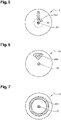
- the peripheral portions 40 and central 42 are visible in figure 5 .
- the longitudinal dimension of the viewing window 38 along the first direction is preferably equal to or greater than 10% of the dimension of the front wall 18 or bottom 20 along this same first direction.
- the viewing window 38 preferably extends along the first direction by a length at least equal to 10% of the diameter of the front wall 18 or bottom 20.
- Embodiments of the viewing window are visible in figures 5 to 8 .
- a first embodiment visible in figure 5 has a viewing window 38A of rectangular or oblong shape extending mainly along the first direction.
- a second embodiment visible in figure 6 has a viewing window 38B in the shape of an angular sector around the main axis A, possibly truncated in its lower part.
- a third embodiment visible in figure 7 presents a viewing window 38C of annular shape around the main axis A.
- a fourth embodiment visible in figure 8 features a circular shaped 38D viewing window.
- the viewing window 38 can cover a significant part of the front wall 18 or bottom 20.
- the viewing window 38 can form at least 40%, at least 60% or even at least 70% of the surface of the front wall 18 or bottom 20.
- the transport device 10 may further comprise an anchoring member 44 fixed to the casing 12.
- This anchoring member 44 is configured to make it possible to anchor the casing 12 to a point of support during the unwinding of the cable.
- the anchoring member 44 can take the form of an eyelet added or formed in the envelope 12.
Landscapes
- Guides For Winding Or Rewinding, Or Guides For Filamentary Materials (AREA)
- Storage Of Web-Like Or Filamentary Materials (AREA)
Applications Claiming Priority (1)
| Application Number | Priority Date | Filing Date | Title |
|---|---|---|---|
| FR2009835A FR3114678B1 (fr) | 2020-09-28 | 2020-09-28 | Dispositif de transport pour une couronne de câble avec tube redresseur |
Publications (3)
| Publication Number | Publication Date |
|---|---|
| EP3974363A1 true EP3974363A1 (de) | 2022-03-30 |
| EP3974363C0 EP3974363C0 (de) | 2025-10-29 |
| EP3974363B1 EP3974363B1 (de) | 2025-10-29 |
Family
ID=73498029
Family Applications (1)
| Application Number | Title | Priority Date | Filing Date |
|---|---|---|---|
| EP21306328.2A Active EP3974363B1 (de) | 2020-09-28 | 2021-09-24 | Transportvorrichtung für eine kabelrolle mit einem richtrohr |
Country Status (2)
| Country | Link |
|---|---|
| EP (1) | EP3974363B1 (de) |
| FR (1) | FR3114678B1 (de) |
Citations (4)
| Publication number | Priority date | Publication date | Assignee | Title |
|---|---|---|---|---|
| US5100078A (en) * | 1991-05-09 | 1992-03-31 | Optelecom, Inc. | Method and apparatus for controlling optical fiber payout from the inside of a wound package of optical fiber |
| US20050224615A1 (en) * | 2004-04-01 | 2005-10-13 | Miller Lisa K | Flexible cable container payout tube |
| US20170043974A1 (en) * | 2015-08-14 | 2017-02-16 | Reelex Packaging Solutions, Inc. | Coil Package Payout Tube Assembly |
| EP3275622A2 (de) * | 2016-07-28 | 2018-01-31 | Nest S.r.l. | Spule und verfahren zur herstellung einer solchen spule |
Family Cites Families (1)
| Publication number | Priority date | Publication date | Assignee | Title |
|---|---|---|---|---|
| AU3999899A (en) * | 1998-05-15 | 1999-12-06 | Goldwitz Limited Family Partnership, The | Wire and cable dispenser |
-
2020
- 2020-09-28 FR FR2009835A patent/FR3114678B1/fr active Active
-
2021
- 2021-09-24 EP EP21306328.2A patent/EP3974363B1/de active Active
Patent Citations (4)
| Publication number | Priority date | Publication date | Assignee | Title |
|---|---|---|---|---|
| US5100078A (en) * | 1991-05-09 | 1992-03-31 | Optelecom, Inc. | Method and apparatus for controlling optical fiber payout from the inside of a wound package of optical fiber |
| US20050224615A1 (en) * | 2004-04-01 | 2005-10-13 | Miller Lisa K | Flexible cable container payout tube |
| US20170043974A1 (en) * | 2015-08-14 | 2017-02-16 | Reelex Packaging Solutions, Inc. | Coil Package Payout Tube Assembly |
| EP3275622A2 (de) * | 2016-07-28 | 2018-01-31 | Nest S.r.l. | Spule und verfahren zur herstellung einer solchen spule |
Also Published As
| Publication number | Publication date |
|---|---|
| EP3974363C0 (de) | 2025-10-29 |
| EP3974363B1 (de) | 2025-10-29 |
| FR3114678A1 (fr) | 2022-04-01 |
| FR3114678B1 (fr) | 2026-01-02 |
Similar Documents
| Publication | Publication Date | Title |
|---|---|---|
| EP1581830A1 (de) | Spule zur aufbewahrung mit vorrichtung zum abrollen von optischen kabeln | |
| FR2728079A1 (fr) | Dispositif de maintien d'au moins un cable a fibres optiques et boitier d'epissurage en faisant application | |
| EP0978746A1 (de) | Verbindungsvorrichtung für faseroptische Kabel | |
| WO2001011742A1 (fr) | Dispositif de guidage d'au moins un element longiligne souple, tel que cable ou autre, a contour substantiellement ferme | |
| EP3025053B1 (de) | Segmentierte windturbinenschaufel und windturbine mit solch einer schaufel | |
| FR2549923A1 (fr) | Serre-cable de frettage | |
| FR2958461A1 (fr) | Dispositif d'ancrage d'un cable sur un support | |
| EP3974363B1 (de) | Transportvorrichtung für eine kabelrolle mit einem richtrohr | |
| FR3114577A1 (fr) | Dispositif de transport pour une couronne de câble avec une fenêtre de visualisation | |
| EP2993151B1 (de) | Hochleistungs-trommel | |
| EP3025054B1 (de) | Segmentierte windturbinenschaufel mit einer montagevorrichtung | |
| EP0531274B1 (de) | Befestigungsvorrichtung für ein Tuch auf einem Wickelträger | |
| FR2565067A1 (fr) | Dispositif d'accrochage du fil pour moulinet de peche | |
| EP4707505A1 (de) | Diebstahlsicherungsvorrichtung mit einziehbaren kabeln, insbesondere für selbstbedienungsartikel | |
| FR3001517A1 (fr) | Bloqueur de cordage. | |
| EP2390462B1 (de) | Verfahren und Zubehör zum Einbau eines Belüftungsschlauches in einem unterirsdischen Schacht | |
| BE1017124A6 (fr) | Dispositif a rideau flexible. | |
| FR2630421A1 (fr) | Dispositif d'enroulement, de portage et de deroulement de bobines de fil en particulier de ronces artificielles | |
| EP1795480B1 (de) | Demontierbare Spule zum Abwickeln wenigstens einer Wicklung und Verfahren zur Montage einer Spule mit gleichzeitiger Anordnung einer oder mehrerer Wicklung(en) | |
| FR2652070A1 (fr) | Dispositif enrouleur et derouleur de cable. | |
| FR2702928A3 (fr) | Réceptacle pour le logement de cordons, notamment de fils de lignes pour cannes à pêche. | |
| EP4726941A2 (de) | Multifunktionales halteclip und halter dafür | |
| FR2617819A1 (fr) | Dispositif derouleur de bobines de films en matiere plastique etirable et auto-adhesive pour fardelage de produits divers | |
| FR2582187A1 (fr) | Enrouleur de cordeau et son piquet | |
| WO2012123373A1 (fr) | Dispositif d'extraction d'un element optique dans un cable optique et procede d'extraction associe |
Legal Events
| Date | Code | Title | Description |
|---|---|---|---|
| PUAI | Public reference made under article 153(3) epc to a published international application that has entered the european phase |
Free format text: ORIGINAL CODE: 0009012 |
|
| STAA | Information on the status of an ep patent application or granted ep patent |
Free format text: STATUS: THE APPLICATION HAS BEEN PUBLISHED |
|
| AK | Designated contracting states |
Kind code of ref document: A1 Designated state(s): AL AT BE BG CH CY CZ DE DK EE ES FI FR GB GR HR HU IE IS IT LI LT LU LV MC MK MT NL NO PL PT RO RS SE SI SK SM TR |
|
| STAA | Information on the status of an ep patent application or granted ep patent |
Free format text: STATUS: REQUEST FOR EXAMINATION WAS MADE |
|
| 17P | Request for examination filed |
Effective date: 20220930 |
|
| RBV | Designated contracting states (corrected) |
Designated state(s): AL AT BE BG CH CY CZ DE DK EE ES FI FR GB GR HR HU IE IS IT LI LT LU LV MC MK MT NL NO PL PT RO RS SE SI SK SM TR |
|
| STAA | Information on the status of an ep patent application or granted ep patent |
Free format text: STATUS: EXAMINATION IS IN PROGRESS |
|
| 17Q | First examination report despatched |
Effective date: 20231124 |
|
| GRAP | Despatch of communication of intention to grant a patent |
Free format text: ORIGINAL CODE: EPIDOSNIGR1 |
|
| STAA | Information on the status of an ep patent application or granted ep patent |
Free format text: STATUS: GRANT OF PATENT IS INTENDED |
|
| INTG | Intention to grant announced |
Effective date: 20250603 |
|
| GRAS | Grant fee paid |
Free format text: ORIGINAL CODE: EPIDOSNIGR3 |
|
| GRAA | (expected) grant |
Free format text: ORIGINAL CODE: 0009210 |
|
| STAA | Information on the status of an ep patent application or granted ep patent |
Free format text: STATUS: THE PATENT HAS BEEN GRANTED |
|
| AK | Designated contracting states |
Kind code of ref document: B1 Designated state(s): AL AT BE BG CH CY CZ DE DK EE ES FI FR GB GR HR HU IE IS IT LI LT LU LV MC MK MT NL NO PL PT RO RS SE SI SK SM TR |
|
| REG | Reference to a national code |
Ref country code: CH Ref legal event code: F10 Free format text: ST27 STATUS EVENT CODE: U-0-0-F10-F00 (AS PROVIDED BY THE NATIONAL OFFICE) Effective date: 20251029 Ref country code: GB Ref legal event code: FG4D Free format text: NOT ENGLISH |
|
| REG | Reference to a national code |
Ref country code: DE Ref legal event code: R096 Ref document number: 602021041200 Country of ref document: DE |
|
| REG | Reference to a national code |
Ref country code: IE Ref legal event code: FG4D Free format text: LANGUAGE OF EP DOCUMENT: FRENCH |
|
| U01 | Request for unitary effect filed |
Effective date: 20251125 |
|
| U07 | Unitary effect registered |
Designated state(s): AT BE BG DE DK EE FI FR IT LT LU LV MT NL PT RO SE SI Effective date: 20251201 |
|
| PG25 | Lapsed in a contracting state [announced via postgrant information from national office to epo] |
Ref country code: ES Free format text: LAPSE BECAUSE OF FAILURE TO SUBMIT A TRANSLATION OF THE DESCRIPTION OR TO PAY THE FEE WITHIN THE PRESCRIBED TIME-LIMIT Effective date: 20251029 |
|
| PG25 | Lapsed in a contracting state [announced via postgrant information from national office to epo] |
Ref country code: NO Free format text: LAPSE BECAUSE OF FAILURE TO SUBMIT A TRANSLATION OF THE DESCRIPTION OR TO PAY THE FEE WITHIN THE PRESCRIBED TIME-LIMIT Effective date: 20260129 |
|
| PG25 | Lapsed in a contracting state [announced via postgrant information from national office to epo] |
Ref country code: HR Free format text: LAPSE BECAUSE OF FAILURE TO SUBMIT A TRANSLATION OF THE DESCRIPTION OR TO PAY THE FEE WITHIN THE PRESCRIBED TIME-LIMIT Effective date: 20251029 |
|
| PG25 | Lapsed in a contracting state [announced via postgrant information from national office to epo] |
Ref country code: RS Free format text: LAPSE BECAUSE OF FAILURE TO SUBMIT A TRANSLATION OF THE DESCRIPTION OR TO PAY THE FEE WITHIN THE PRESCRIBED TIME-LIMIT Effective date: 20260129 |
|
| PG25 | Lapsed in a contracting state [announced via postgrant information from national office to epo] |
Ref country code: IS Free format text: LAPSE BECAUSE OF FAILURE TO SUBMIT A TRANSLATION OF THE DESCRIPTION OR TO PAY THE FEE WITHIN THE PRESCRIBED TIME-LIMIT Effective date: 20260228 |
|
| PG25 | Lapsed in a contracting state [announced via postgrant information from national office to epo] |
Ref country code: PL Free format text: LAPSE BECAUSE OF FAILURE TO SUBMIT A TRANSLATION OF THE DESCRIPTION OR TO PAY THE FEE WITHIN THE PRESCRIBED TIME-LIMIT Effective date: 20251029 |