EP3974364A1 - Machine de texturation de faux fils tordus - Google Patents
Machine de texturation de faux fils tordus Download PDFInfo
- Publication number
- EP3974364A1 EP3974364A1 EP21198498.4A EP21198498A EP3974364A1 EP 3974364 A1 EP3974364 A1 EP 3974364A1 EP 21198498 A EP21198498 A EP 21198498A EP 3974364 A1 EP3974364 A1 EP 3974364A1
- Authority
- EP
- European Patent Office
- Prior art keywords
- tension
- yarn
- detection device
- false
- knot
- Prior art date
- Legal status (The legal status is an assumption and is not a legal conclusion. Google has not performed a legal analysis and makes no representation as to the accuracy of the status listed.)
- Granted
Links
Images



Classifications
-
- B—PERFORMING OPERATIONS; TRANSPORTING
- B65—CONVEYING; PACKING; STORING; HANDLING THIN OR FILAMENTARY MATERIAL
- B65H—HANDLING THIN OR FILAMENTARY MATERIAL, e.g. SHEETS, WEBS, CABLES
- B65H49/00—Unwinding or paying-out filamentary material; Supporting, storing or transporting packages from which filamentary material is to be withdrawn or paid-out
- B65H49/02—Methods or apparatus in which packages do not rotate
- B65H49/04—Package-supporting devices
- B65H49/10—Package-supporting devices for one operative package and one or more reserve packages
- B65H49/12—Package-supporting devices for one operative package and one or more reserve packages the reserve packages being mounted to permit manual or automatic transfer to operating position
-
- D—TEXTILES; PAPER
- D02—YARNS; MECHANICAL FINISHING OF YARNS OR ROPES; WARPING OR BEAMING
- D02G—CRIMPING OR CURLING FIBRES, FILAMENTS, THREADS, OR YARNS; YARNS OR THREADS
- D02G1/00—Producing crimped or curled fibres, filaments, yarns, or threads, giving them latent characteristics
- D02G1/02—Producing crimped or curled fibres, filaments, yarns, or threads, giving them latent characteristics by twisting, fixing the twist and backtwisting, i.e. by imparting false twist
- D02G1/0206—Producing crimped or curled fibres, filaments, yarns, or threads, giving them latent characteristics by twisting, fixing the twist and backtwisting, i.e. by imparting false twist by false-twisting
- D02G1/0266—Producing crimped or curled fibres, filaments, yarns, or threads, giving them latent characteristics by twisting, fixing the twist and backtwisting, i.e. by imparting false twist by false-twisting false-twisting machines
-
- B—PERFORMING OPERATIONS; TRANSPORTING
- B65—CONVEYING; PACKING; STORING; HANDLING THIN OR FILAMENTARY MATERIAL
- B65H—HANDLING THIN OR FILAMENTARY MATERIAL, e.g. SHEETS, WEBS, CABLES
- B65H63/00—Warning or safety devices, e.g. automatic fault detectors, stop-motions ; Quality control of the package
- B65H63/02—Warning or safety devices, e.g. automatic fault detectors, stop-motions ; Quality control of the package responsive to reduction in material tension, failure of supply, or breakage, of material
-
- B—PERFORMING OPERATIONS; TRANSPORTING
- B65—CONVEYING; PACKING; STORING; HANDLING THIN OR FILAMENTARY MATERIAL
- B65H—HANDLING THIN OR FILAMENTARY MATERIAL, e.g. SHEETS, WEBS, CABLES
- B65H63/00—Warning or safety devices, e.g. automatic fault detectors, stop-motions ; Quality control of the package
- B65H63/08—Warning or safety devices, e.g. automatic fault detectors, stop-motions ; Quality control of the package responsive to delivery of a measured length of material, completion of winding of a package, or filling of a receptacle
- B65H63/086—Warning or safety devices, e.g. automatic fault detectors, stop-motions ; Quality control of the package responsive to delivery of a measured length of material, completion of winding of a package, or filling of a receptacle responsive to completion of unwinding of a package
-
- D—TEXTILES; PAPER
- D01—NATURAL OR MAN-MADE THREADS OR FIBRES; SPINNING
- D01H—SPINNING OR TWISTING
- D01H13/00—Other common constructional features, details or accessories
- D01H13/32—Counting, measuring, recording or registering devices
-
- D—TEXTILES; PAPER
- D02—YARNS; MECHANICAL FINISHING OF YARNS OR ROPES; WARPING OR BEAMING
- D02G—CRIMPING OR CURLING FIBRES, FILAMENTS, THREADS, OR YARNS; YARNS OR THREADS
- D02G1/00—Producing crimped or curled fibres, filaments, yarns, or threads, giving them latent characteristics
- D02G1/02—Producing crimped or curled fibres, filaments, yarns, or threads, giving them latent characteristics by twisting, fixing the twist and backtwisting, i.e. by imparting false twist
- D02G1/0206—Producing crimped or curled fibres, filaments, yarns, or threads, giving them latent characteristics by twisting, fixing the twist and backtwisting, i.e. by imparting false twist by false-twisting
-
- B—PERFORMING OPERATIONS; TRANSPORTING
- B65—CONVEYING; PACKING; STORING; HANDLING THIN OR FILAMENTARY MATERIAL
- B65H—HANDLING THIN OR FILAMENTARY MATERIAL, e.g. SHEETS, WEBS, CABLES
- B65H2701/00—Handled material; Storage means
- B65H2701/30—Handled filamentary material
- B65H2701/31—Textiles threads or artificial strands of filaments
Definitions
- the present invention relates to a false-twist texturing machine.
- a false-twist texturing machine processes a yarn supplied from a yarn feeding package in which a raw yarn is wound and manufactures a winding package in which the processed yarn is wound.
- two yarn feeding packages are installed and a yarn end (tail yarn) of one yarn feeding package is connected to a yarn end (mouth yarn) of the other yarn feeding package. Accordingly, the yarns of two yarn feeding packages are connected to one.
- the yarn is continuously supplied from the yarn feeding package to the false-twist texturing machine.
- a knot is formed at a position in which the yarn ends of two yarn feeding packages are connected. For example, in the false-twist texturing machine described in Patent Literature 1 (International Publication WO 2001/83348 ), the switching of the yarn feeding package is detected by detecting the movement of the knot.
- a yarn splicing operation between the yarn end of one yarn feeding package and the yarn end of the other yarn feeding package is manually performed by an operator.
- the result of knotting may differ depending on the skill and proficiency of the operator. Then, since the result of knotting affects the properties of the yarn after false-twist texturing when the knot is false-twist textured, the untwisting tension or the like of the false-twist textured knot may become unstable in some cases. Therefore, in general, when the knot is included in the winding package, the quality (grade) of the winding package is set low. However, not all knots affect the quality of the winding package.
- An object of an aspect of the present invention is to provide a false-twist texturing machine capable of specifying the untwisting tension of the false-twist textured knot.
- a false-twist texturing machine is a false-twist texturing machine for forming a winding package by performing false-twist texturing on a yarn supplied from a yarn feeding package, the false-twist texturing machine including a tension detection device which detects an untwisting tension of the yarn traveling between the yarn feeding package and the winding package; a switching detection device which detects that the yarn feeding package supplying the yarn has been switched from one yarn feeding package to the other yarn feeding package; and an information processing device which calculates a period of movement time at which a knot of a yarn end of the one yarn feeding package and a yarn end of the other yarn feeding package is expected to move in the tension detection device based on the detection result of the switching detection device and extracts and stores tension a tension data group corresponding to the period of movement time from the detection result of the tension detection device.
- the information processing device calculates the period of movement time at which the knot is expected to move in the tension detection device and extracts and stores the tension data group corresponding to the period of movement time from the detection result of the tension detection device. Accordingly, it is possible to specify the untwisting tension of the false-twist textured knot.
- the information processing device may determine that the untwisting tension of the yarn is abnormal when a value of the untwisting tension of the yarn exceeds a threshold value in the detection result of the tension detection device, may extract a tension data group when the abnormality is detected from the detection result of the tension detection device, and may store the tension data group related to the abnormality such that the tension data group related to the abnormality is distinguishable from a data group related to the knot.
- the information processing device may calculate a reference movement time at which the knot is expected to move in the tension detection device based on the detection result of the tension detection device, may extract a tension data group in a predetermined time range including the reference movement time based on the reference movement time.
- the period of movement time at which the knot is expected to move in the tension detection device can be calculated based on the reference movement time. Also, since the tension data group of the period of movement time can be confirmed, the data group can be managed with the movement time as a reference.
- the information processing device may calculate the reference movement time based on a switching time at which the switching detection device detects that the yarn feeding package supplying the yarn is switched from one yarn feeding package to the other yarn feeding package, a traveling speed of the yarn, and a distance of a traveling path of the yarn between the switching detection device and the tension detection device. In this configuration, it is possible to calculate the reference movement time with high accuracy.
- the information processing device may be provided with an output unit outputting a waveform created based on a tension value and time in the stored tension data group.
- the waveform is visually confirmed with the output unit, the condition of the false-twist textured knot can be confirmed.
- the tension data group related to untwisting tension of the false-twist textured knot can be used as an index of quality evaluation Therefore, in the false-twist texturing machine, the quality of the winding package can be evaluated with details.
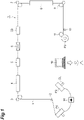
- a false-twist texturing machine 1 processes a yarn Y supplied from yarn feeding packages P1 and P2 to manufacture a winding package P3.
- the yarn Y is a synthetic fiber made of a thermoplastic synthetic fiber such as polyester or polyamide.
- the yarn feeding packages P1 and P2 are formed by winding a partially oriented yarn (POY) on a yarn feeding bobbin (not shown).
- the winding package P3 is formed by winding a draw textured yarn (DTY) on a winding bobbin (not shown).
- the false-twist texturing machine 1 includes a yarn guide 2, a first yarn feeding roller mechanism 3, a first heating device 4, a cooling device 5, a false-twisting device 6, a second yarn feeding roller mechanism 7, a second heating device 8, a third yarn feeding roller mechanism 9, a traverse device 10, and a winding roller mechanism 11. Further, the false-twist texturing machine 1 includes a tension detection device 20, a switching detection device 30, and an information processing device 40.
- the yarn guide 2, the first yarn feeding roller mechanism 3, the first heating device 4, the cooling device 5, the false-twisting device 6, the second yarn feeding roller mechanism 7, the second heating device 8, the third yarn feeding roller mechanism 9, the traverse device 10, and the winding roller mechanism 11 are provided in this order from the upstream side in the traveling direction of the yarn Y.
- the yarn Y is supplied from the yarn feeding packages P1 and P2 to the false-twist texturing machine 1.
- the yarn feeding packages P1 and P2 are supported by a creel CL provided on a creel stand (not shown).
- one yarn feeding package supplies the yarn Y to the false-twist texturing machine 1 and the other yarn feeding package waits to continuously supply the yarn Y to the false-twist texturing machine 1.
- the yarn Y is supplied from the yarn feeding package P1 and the yarn feeding package P2 is in a standby state.
- the yarn guide 2 guides the yarn Y supplied from the yarn feeding packages P1 and P2 to the first yarn feeding roller mechanism 3.
- the yarn guide 2 is a tubular member and guides the yarn Y by inserting the yarn Y thereinto.
- the first yarn feeding roller mechanism 3 pulls out the yarn Y supplied from the yarn guide 2 by a pair of rollers (driving roller, driven roller).
- the first yarn feeding roller mechanism 3 conveys the yarn Y at a constant speed.
- the first heating device 4 performs a heating treatment on the yarn Y
- the cooling device 5 cools the yarn Y heated by the first heating device 4.
- the false-twisting device 6 performs false-twisting on the yarn Y
- the second yarn feeding roller mechanism 7 pulls out the yarn Y that has moved the tension detection device 20 by a pair of rollers.
- a speed at which the second yarn feeding roller mechanism 7 conveys the yarn Y is different from a speed at which the first yarn feeding roller mechanism 3 conveys the yarn Y
- the second yarn feeding roller mechanism 7 conveys the yarn Y at a constant speed faster than that of the first yarn feeding roller mechanism 3. Accordingly, the yarn Y is stretched between the first yarn feeding roller mechanism 3 and the second yarn feeding roller mechanism 7.
- the second heating device 8 performs a heating treatment on the yarn Y.
- the third yarn feeding roller mechanism 9 pulls out the yarn Y that has moved the second heating device 8 by a pair of rollers. A speed at which the third yarn feeding roller mechanism 9 conveys the yarn Y is different from a speed at which the second yarn feeding roller mechanism 7 conveys the yarn Y.
- the third yarn feeding roller mechanism 9 conveys the yarn Y at a constant speed slower than that of the second yarn feeding roller mechanism 7. Accordingly, the yarn Y is relaxed between the second yarn feeding roller mechanism 7 and the third yarn feeding roller mechanism 9.
- the traverse device 10 traverses the yarn Y
- the winding roller mechanism 11 contacts the winding package P3 and rotationally drives the winding package P3. Accordingly, the yarn Y is wound on the winding package P3 while being traversed.
- the tension detection device 20 detects the untwisting tension of the yarn Y that has been false-twisted by the false-twisting device 6. That is, the tension detection device 20 is provided between the false-twisting device 6 and the second yarn feeding roller mechanism 7.
- the tension detection device 20 outputs a detected tension signal to the information processing device 40.
- the tension detection device 20 a known device such as a mechanical type or an optical type can be adopted. A specific method for the tension detection will be described below.
- a voltage value is acquired from a sensor in the tension detection device 20 at predetermined intervals (for example, 10 milliseconds). The acquired voltage is transmitted to the information processing device 40 as a tension signal.
- the switching detection device 30 detects the switching of the yarn feeding packages P1 and P2.
- one yarn feeding package (the yarn feeding package on one side) supplies the yarn Y to the false-twist texturing machine 1 and the other yarn feeding package (the yarn feeding package on the other side) waits to continuously supply the yarn Y to the false-twist texturing machine 1.
- the yarn end (tail yarn) on the inner layer side of one yarn feeding package and the yarn end (mouth yarn) on the outer layer side of the other yarn feeding package are entangled.
- the yarn Y is continuously supplied from the yarn feeding packages P1 and P2 to the false-twist texturing machine 1.
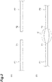
- a knot C formed by entangling the tail yarn and the mouth yarn is formed in such a manner that the tail yarn which is a yarn end Y1 on the inner layer side of the yarn feeding package P1 shown in FIG. 2(a) is entangled with the mouth yarn which is a yarn end Y2 on the outer layer side of the yarn feeding package P2 shown in FIG. 2(b) .
- the knot C is formed at a portion in which two yarn ends Y1 and Y2 are entangled.
- the knot C may be formed by knotting the tail yarn with the mouth yarn, instead of entangling.
- the switching detection device 30 detects the switching of the yarn feeding packages P1 and P2 by detecting the movement of the knot C at a predetermined position of the switching detection device 30.
- the switching detection device 30 outputs a switching signal related to the detected switching to the information processing device 40.
- a known device such as a mechanical type or an optical type can be adopted.
- the setting of the yarn Y (knot C) at a predetermined position of the switching detection device 30 is performed by, for example, an operator who performed a yarn splicing operation.
- the switching detection device 30 changes from the state without the yarn to the state with the yarn.
- the output signal of the switching detection device 30 changes from the low voltage state to the high voltage state due to the change in the state of the switching detection device 30.
- the knot C is set to the predetermined position of the switching detection device 30.
- the output signal of the switching detection device 30 changes from a high voltage state to a low voltage state due to a change in the state of the switching detection device 30.
- the low voltage state continues for a predetermined time from the time at which the output signal of the switching detection device 30 changes from the high voltage state to the low voltage state, it is recognized that the yarn feeding packages P1 and P2 are switched and the knot C is set to the predetermined position of the switching detection device 30.
- the voltage value acquired by the switching detection device 30 is transmitted to the information processing device 40 as the switching signal. Additionally, the output signal of the switching detection device 30 when the knot C is set to the predetermined position of the switching detection device 30 changes from the low voltage state to the high voltage state, but may change from the high voltage state to the low voltage state.
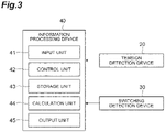
- the information processing device 40 is a processor having an integrated circuit mounted thereon or a computer system equipped with the processor.
- the information processing device 40 is a part that controls various operations in the false-twist texturing machine 1 and manages the false-twist texturing machine and includes a CPU (Central Processing Unit), a ROM (Read Only Memory), a RAM (Random Access Memory), and the like together with an input/output interface and the like.
- Various data or programs are stored in the ROM, and these data or the like are expanded in the RAM and processed by the CPU.
- the input/output interface for example, an input device such as a keyboard and a mouse or an output device such as a monitor and a speaker are used.
- the information processing device is communicably connected to the tension detection device and the switching detection device via the input/output interface.
- the information processing device 40 includes an input unit 41, a control unit 42, a storage unit 43, a calculation unit 44, and an output unit 45.
- the input unit 41 receives a signal or data from a connected external device, and transmits the data or the like to the control unit 42.
- the input unit 41 receives data or the like input by the operator via the input device, for example, the traveling speed (unwinding speed) of the yarn Y, the traveling path of the yarn Y between the switching detection device 30 and the tension detection device 20, and a threshold value for determining tension abnormality and transmits them to the control unit 42. These data or the like may be changed as appropriate depending on the conditions such as the used equipment and the used yarn.
- the input unit 41 receives a tension signal output from the tension detection device 20 and a switching signal output from the switching detection device 30 and transmits them to the control unit 42.
- the control unit 42 controls each unit constituting the information processing device 40.
- the control unit 42 controls the storage unit 43 to write and call the data or the like according to the data or the like from the input unit 41, the calculation unit 44, or the storage unit 43.
- the control unit 42 controls the calculation unit 44 to execute a calculation according to data or the like from the input unit 41, the calculation unit 44, or the storage unit 43.
- the control unit 42 controls the output unit 45 to output the data or the like according to the data or the like from the input unit 41, the calculation unit 44, or the storage unit 43.
- the storage unit 43 stores data or the like based on a command from the control unit 42.
- Examples of the data or the like to be stored include the traveling speed (unwinding speed) of the yarn Y, the distance of the traveling path of the yarn Y between the switching detection device 30 and the tension detection device 20, the threshold value for determining tension abnormality, the tension data, and the switching data. Further examples of the data or the like to be stored include the calculation result obtained by the calculation unit 44.
- the calculation unit 44 processes data or the like based on a command from the control unit 42. A specific process of the calculation unit 44 will be described below.
- the output unit 45 outputs data or the like based on a command from the control unit 42.
- a display device such as a display can be used. A specific output of the display device will be described below.
- the information processing device 40 receives the tension signal transmitted from the tension detection device 20.
- the input unit 41 converts the received tension signal into a tension value according to a predetermined correction calculation such as A/D conversion and a predetermined filter.
- the input unit 41 transmits the converted tension value to the control unit 42.
- the control unit 42 that has received the tension value transmits the tension value and the time at which the tension value is received from the input unit 41 to the calculation unit 44 and instructs the calculation unit 44 to perform a process of associating the time with the tension value.
- the calculation unit 44 executes a command from the control unit 42 and transmits the calculation result (tension data associated with the time) to the control unit 42.
- the control unit 42 receives the tension data from the calculation unit 44 and stores the tension data in the storage unit 43. Then, the tension data sequentially transmitted from the tension detection device 20 to the information processing device 40 is stored in the storage unit 43 in this way.
- the information processing device 40 receives the switching signal transmitted from the switching detection device 30.
- the input unit 41 performs I/O conversion on the received switching signal to obtain a switching value.
- the input unit 41 transmits the converted switching value to the control unit 42.
- the control unit 42 that has received the switching value transmits the switching value and the time at which the switching value is received from the input unit 41 to the calculation unit 44 and instructs the calculation unit 44 to perform a process of associating the time with the switching value.
- the calculation unit 44 executes a command from the control unit 42 and transmits the calculation result (switching data associated with the time) to the control unit 42.
- the control unit 42 receives the switching data from the calculation unit 44 and stores the switching data in the storage unit 43. Then, the switching data sequentially transmitted from the switching detection device 30 to the information processing device 40 is stored in the storage unit 43 in this way.
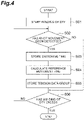
- the information processing device 40 determines whether or not the yarn feeding packages P1 and P2 are switched, that is, the knot C is removed from a predetermined position of the switching detection device 30 based on the detection result of the switching detection device 30 (step S02).
- step S02: YES When the information processing device 40 determines that the knot C is removed from a predetermined position of the switching detection device 30, that is, the yarn feeding packages P1 and P2 are switched (step S02: YES), the process of the information processing device 40 proceeds to step S03. On the other hand, when the information processing device 40 determines that the knot C is not removed from a predetermined position of the switching detection device 30, that is, the yarn feeding packages P1 and P2 are not switched (step S02: NO), the process of the information processing device 40 proceeds to step S06.
- the information processing device 40 stores the switching time based on the switching signal output from the switching detection device 30 to the information processing device 40 (step S03). Subsequently, the information processing device 40 calculates the reference movement time at which the knot C is expected to move in the tension detection device 20 (step S04). The information processing device 40 extracts the tension data group in a predetermined time range including the reference movement time based also on the calculated reference movement time and store the tension data group (step S05).
- the information processing device 40 determines whether or not the winding of the yarn Y of the false-twist texturing machine 1 ends (step S06). When the information processing device 40 determines that the false-twist texturing machine 1 ends the winding of the yarn Y (step S06: YES), the information processing device 40 ends the process. When the information processing device 40 does not determine that the false-twist texturing machine 1 ends the winding of the yarn Y (step S06: NO), the information processing device 40 returns to the process of step S02 and performs the process after step S02.
- the information processing device 40 calculates a reference movement time at which the knot C is expected to move in the tension detection device 20 based on the detection result of the switching detection device 30 as described in step S04.
- the control unit 42 acquires the switching signal, the time at which the switching signal is acquired, the traveling speed (unwinding speed) of the yarn Y, and the distance of the traveling path of the yarn Y between the switching detection device 30 and the tension detection device 20 from the storage unit 43. Then, a command of calculating the time at which the knot C is expected to move in the tension detection device 20 based on these data or the like is transmitted to the calculation unit 44.
- the calculation unit 44 calculates the time at which the knot C is expected to move in the tension detection device 20 based on these data or the like and transmits the calculated time to the control unit 42 as the reference knot movement time.
- the information processing device 40 extracts and stores the tension data group in a predetermined time range including the reference movement time based on the reference movement time at which the knot C is expected to move in the tension detection device 20 based on the detection result of the tension detection device 20 as described in step S05.
- the control unit 42 extracts the tension data group of a predetermined time including the reference knot movement time from the storage unit 43 based on the calculation result. Specifically, the control unit 42 extracts the tension data in a range including a predetermined time (for example, every 5 seconds around a reference time) before and after the knot movement time which is a reference (center) as the tension data group related to the knot movement.
- the control unit 42 instructs the storage unit 43 to store the extracted tension data group related to the knot movement in the storage unit 43.
- the control unit 42 instructs the storage unit 43 to store the tension data group related to the knot movement by setting a flag representing the tension data group of the "knot movement" to the tension data group related to the knot movement.
- the control unit 42 instructs the calculation unit 44 to create image data related to the display screen displayed on the display device based on the extracted tension data group.
- the information processing device 40 extracts and stores the tension data group of the false-twist textured knot C with reference to Fig. 4 . Specifically, the information processing device 40 calculates the reference movement time at which the knot C is expected to move in the tension detection device 20, and based on the calculated reference movement time, a tension data group in a predetermined time range including the reference movement time is extracted and stored.
- the following describes a feature of the information processing device 40 extracting and storing the tension data group of a false-twist textured knot C.
- the information processing device 40 calculates a reference movement time at which the knot C is expected to move in the tension detection device 20, and based on the calculated reference movement time, a tension data group in a predetermined time range including the reference movement time is extracted, which means that the information processing device 40 calculates the period of movement time based on the time at which the knot C is expected to move in the tension detection device 20.
- the period of movement time means the period from the time when the knot C starts to move to the time when the knot C stops to move in the tension detection device 20.
- the information processing unit 40 extracts and stores a tension data group in a predetermined time range including a reference movement time based on the calculated reference movement time, which means that the information processing unit 40 extracts and stores a tension data group corresponding to the period of movement time based on the calculated period of time and the detection result of the tension detection device 20.
- the tension data group corresponding to the period of movement time may include the tension data group of the movement time at which the knot C is expected to start to move and the knot C is expected to stop to move in the tension detection device 20, and also tension data groups therebefore and thereafter.
- step S11 when the false-twist texturing machine 1 starts the winding of the yarn Y (DTY) (step S11), the information processing device 40 determines whether or not the tension value exceeds a threshold value, that is, tension abnormality occurs based on the detection result of the tension detection device 20 (step S12).
- step S12 determines that the tension value exceeds the threshold value, that is, tension abnormality occurs (step S12: YES)
- step S13 On the other hand, when the information processing device 40 does not determine that the tension value exceeds the threshold value, that is, tension abnormality occurs (step S12: NO)
- step S15 when the information processing device 40 does not determine that the tension value exceeds the threshold value, that is, tension abnormality occurs
- the information processing device 40 stores the abnormality detection time based on the tension signal output from the tension detection device 20 to the information processing device 40 (step S13). Subsequently, the information processing device 40 extracts the tension data group corresponding to the abnormality detection time and stores the tension data group (step S14).
- the information processing device 40 determines whether or not the false-twist texturing machine 1 ends the winding of the yarn Y (step S15).
- the information processing device 40 determines that the false-twist texturing machine 1 ends the winding of the yarn Y (step S15: YES)
- the information processing device 40 ends the process.
- the information processing device 40 does not determine that the false-twist texturing machine 1 ends the winding of the yarn Y (step S15: NO)
- the information processing device 40 returns to the process of step S12 and performs the process after step S12.
- the information processing device 40 determines that the untwisting tension of the yarn Y at a certain time is abnormal when the tension value of the yarn Y exceeds the threshold value at the certain time based on the detection result of the tension detection device 20 as described in step S12.
- the control unit 42 acquires the tension data and the threshold value from the storage unit 43. Then, a command of determining whether or not tension abnormality occurs based on these data or the like is transmitted to the calculation unit 44.
- the calculation unit 44 determines whether or not tension abnormality occurs by performing the following calculation. When a state in which the tension value exceeds the threshold value continues for a predetermined time by comparing the tension value with the threshold value, it is determined that tension abnormality occurs. Then, the time at which the tension value exceeds the threshold value is set as the abnormality detection time. Then, as a determination result, the abnormality detection time is transmitted to the control unit 42.
- the information processing device 40 extracts the tension data group corresponding to the abnormality detection time from the detection result of the tension detection device 20 as described in step S14.
- the control unit 42 extracts the tension data group corresponding to the abnormality detection time from the storage unit 43 based on the determination result.
- the control unit 42 extracts the tension data group at a predetermined time including the abnormality detection time.
- the control unit 42 extracts the tension data in a range including a predetermined time (for example, every 5 seconds around a reference time) before and after the abnormality detection time which is a reference (center) as the tension data group related to the tension abnormality.
- the control unit 42 instructs the storage unit 43 to store the extracted tension data group related to the tension abnormality in the storage unit 43 such that the tension data group related to the tension abnormality is distinguishable from the tension data group related to the knot movement.
- control unit 42 instructs the storage unit 43 to store the tension data group related to the tension abnormality by setting thereto a flag representing the tension data group of "tension abnormality.”
- the control unit 42 instructs the calculation unit 44 to create image data related to the display screen displayed on the display device based on the extracted tension data group.
- the display device displays the display screen showing the tension data group of the false-twist textured yarn Y.
- This display screen shows an event that occurs per winding of a certain winding package P3, that is, the tension detection or tension abnormality detection of the false-twist textured knot C.
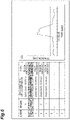
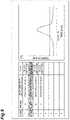
- the display screen is provided with a table showing events on the left side and a graph on the right side. In the table, “number”, “grade”, “date and time of occurrence”, and “type” are provided from the right. The “number” represents a serial number in which the event occurred.
- the “grade” represents the quality of the winding package at the time at which the event occurred. The “grade” is expressed in ascending alphabetical order, of A, B, and C, etc.
- the “grade” has a correlation with tension abnormality detection, and once tension abnormality detection occurs, the quality deteriorates and the alphabet display changes each time.
- the “date and time of occurrence” represents the date and time when the event occurred.
- the “type” represents the type of event
- the “knot movement” represents the tension data group of the false-twist textured knot C
- the “tension abnormality” represents the tension data group in the tension abnormality.
- the graph displays the tension data group corresponding to the event selected in the table as waveform.
- the vertical axis of the graph represents the tension value
- the horizontal axis of the graph represents the time.
- the display unit and display range can be changed as appropriate for both the tension value and the time.
- the display contents of the table and the display contents of the graph are associated with each other in the display table, and when the "number" of the table is selected, the waveform associated with the "number" is displayed in the graph.
- the display table is stored in the storage unit 43 in advance, and when displaying the display screen on the display device, the display table is expanded in the control unit 42 and the calculation unit 44 and image data is created as the calculation result.
- the created image data is transmitted to the display device via the output unit 45, and is displayed on the display device as the display screen.
- the control unit 42 extracts the knot movement time, the tension data group related to the knot movement, the abnormality detection time, the tension data group related to the abnormality detection, and the display table from the storage unit 43.
- the control unit 42 transmits a command of creating the image data to the calculation unit 44 based on the knot movement time, the tension data group related to the knot movement, the abnormality detection time, the tension data group related to the abnormality detection, and the display table extracted as described above.
- the calculation unit 44 calculates and creates image data to be displayed on a table and a graph of the display screen from the knot movement time, the tension data group related to the knot movement, the abnormality detection time, the tension data group related to the abnormality detection, and the display table. Specifically, the following procedure is followed.
- the waveform related to the knot movement and the waveform related to the abnormality detection are respectively created from the tension data group related to the knot movement and the tension data group related to the abnormality detection.
- the knot movement time and the abnormality detection time are entered in the field of the "date and time of occurrence" of the display table.
- the "date and time of occurrence” are sorted in the order of earliest, and they are allocated in ascending order of the "number” in the display table.
- a tag is put in the "type” of the display table to display the "knot movement” in the field of the "type” of the display screen.
- a tag is put in the field of the "type” of the display table to display the "abnormality detection” in the field of the "type” of the display screen in the case of the abnormality detection time associated with the waveform created from the tension data group related to the knot movement time in the display table.
- a tag is put in the "grade” of the display table so that the display of the "grade” of the display screen becomes the display having a lower quality than before.
- the abnormality detection time is associated with the waveform created from the tension data group related to the abnormality detection time in the display table.
- FIGS. 6 and 7 show a winding package P3-1 on August 1, 20XX.
- FIG. 6 shows a state in which the "number” 2 has been selected. Since the user has selected the “number” 2, the column related to the “number” 2 has been changed to a gray background. The “number” 2 has a "date and time of occurrence” of 11:15:05 on August 1, 20XX.
- the “type” is the tension abnormality. Since the tension abnormality is shown in the “number” 2, the quality evaluation is lowered from the “number” 1 and the “grade” is changed from A to B.
- the waveform corresponding to the "number” 2 is displayed.
- the dotted horizontal line in the graph represents a threshold value. A point in time at which the tension value exceeds the threshold value is the abnormality detection time, which corresponds to the "date and time of occurrence" of 11:15:05 on August 1, 20XX indicated by the intersection of the dotted vertical line and the dotted horizontal line.
- FIG. 7 shows a state in which the "number” 3 has been selected. Since the user has selected the “number” 3, the column related to the “number” 3 has been changed to a gray background. The “number” 3 has a "date and time of occurrence” of 13:30:35 on August 1, 20XX. In the “number” 3, the “type” is the knot movement. Since the knot movement is shown in the “number” 3, the “grade” is blank regardless of the quality evaluation of the winding package. In the graph, the waveform corresponding to the "number” 3 is displayed.
- the reference movement time at which the knot is expected to move in the tension detection device corresponds to the "date and time of occurrence" of 13:30:35 on August 1, 20XX, indicated by the intersection of the dotted vertical line and the dotted horizontal line.
- the dotted horizontal line in Fig. 7 represents the threshold value as in Fig. 6
- the dotted horizontal line representing the threshold value is closer to the upper part compared with Fig. 6 because a value of one increment of the tension value in the vertical axis in Fig. 7 is set to be greater than that in Fig. 6 . That is, since the display range of the tension value is set to be broad, and the tension value of the waveform is lower than the threshold value in the graph of Fig.
- the dotted horizontal line representing the threshold value is closer to the upper part of the graph.
- the waveform in the graph of Fig. 7 does not surpass the dotted horizontal line representing the threshold value related to tension abnormality, and the threshold value and the tension value are distanced, which means that the portion related to the false-twist textured knotted C maintains a low tension value.
- the false-twist texturing of this knot C does not have much influence on the untwisting tension.
- FIGS. 8 and 9 show a winding package P3-2 on August 2, 20XX.
- FIG. 8 shows a state in which the "number” 1 is selected. Since the user has selected the “number” 1, the column related to the “number” 1 has been changed to a gray background. The “number” 1 has a "date and time of occurrence” of 10:30:15 on August 2, 20XX.
- the "type” is the tension abnormality. Since the tension abnormality is shown in the “number” 1, the quality evaluation is lowered from the “number” 1 and the “grade” is changed to A.
- the waveform corresponding to the "number” 1 is displayed.
- a value of one increment of the tension value of the vertical axis is equal to that of Fig. 6 .
- the dotted horizontal line in the graph represents a threshold value as in Fig. 6 .
- a point in time at which the tension value exceeds the threshold value is the abnormality detection time, which corresponds to "date and time of occurrence" of 10:30:15 on August 2, 20XX, indicated by the intersection of the dotted vertical line and the dotted horizontal line.
- FIG. 9 shows a state in which the "number” 2 is selected. Since the user has selected the “number” 2, the column related to the “number” 2 has been changed to a gray background. The “number” 2 has a "date and time of occurrence” of 10:30:15 on August 2, 20XX. In the “number” 2, the “type” is knot movement. Since the knot movement is shown in the “number” 2, the “grade” is blank regardless of the quality evaluation of the winding package. In the graph, the waveform corresponding to the "number” 2 is displayed.
- the reference movement time at which the knot is expected to move in the tension detection device corresponds to the "date and time of occurrence" of 10:30:15 on August 2, 20XX indicated by the intersection of the dotted vertical line and the dotted horizontal line.
- a value of one increment of the tension value of the vertical axis is equal to that of Fig. 8 .
- the dotted horizontal line in the graph represents a threshold value as in Fig. 8 . Since the waveform surpasses the dotted horizontal line representing the threshold value related to tension abnormality in the graph of Fig. 9 , that is, the threshold value is surpassed by the tension value, it is considered that the tension abnormality has occurred by false-twist texturing the knot C.
- the information processing device 40 calculates the period of movement time at which the knot C is expected to move in the tension detection device 20 and extracts and stores the tension data group corresponding to the period of movement time from the detection result of the tension detection device 20. Accordingly, it is possible to specify the untwisting tension of the false-twist textured knot C.
- the information processing device 40 determines that the tension of the yarn Y is abnormal when the value of the untwisting tension of the yarn Y in the detection result of the tension detection device 20 exceeds a threshold value. Then, the information processing device 40 extracts the tension data group when the tension abnormality is detected, and stores the extracted tension data group related to tension abnormality such that the tension data group related to tension abnormality is distinguishable from the tension data group related to the knot C. In this configuration, it is possible to distinguish the tension data group related to tension abnormality from the tension data group related to untwisting tension of the false-twist textured knot C.
- the tension data group related to tension abnormality and the tension data group related to untwisting tension of the false-twist textured knot C can be associated each other and stored. Therefore, it becomes easy to compare the tension data group related to tension abnormality with the tension data group related to untwisting tension of the false-twist textured knot C.
- the information processing device 40 calculates a reference knot movement time at which the knot moves in the tension detection device 20 based on the detection result of the switching detection device 30, and extracts and stores the tension data group in a predetermined time range including the reference knot movement time based on the reference knot movement time.
- the period of movement time at which the knot is expected move in the tension detection device can be calculated based on the reference movement time.
- the tension data group of the period of movement time can be confirmed based on the reference movement time, the data group can be managed with the knot movement time as a reference. Therefore, it becomes easy to manage data.
- the information processing device 40 extracts and stores the tension data group in a predetermined time range including the abnormality detection time based on the abnormality detection time at which the information processing device 40 determines that the untwisting tension of the yarn Y is abnormal as a reference.
- the tension data group can be confirmed based on the abnormality detection time, and the data group can be managed with the abnormality detection time as a reference. Therefore, it becomes easy to manage data.
- the information processing device 40 includes the output unit 45 which outputs a waveform created based on the tension value and time in the stored tension data group.
- the waveform related to the untwisting tension of the false-twist textured knot C can be used as an index for quality evaluation. For example, it is possible to evaluate the quality of the winding package P3 step by step based on the tendency of the waveform related to the untwisting tension of the false-twist textured knot C. Thus, it is possible to evaluate the quality of the winding package P3 in the false-twist texturing machine 1.
- a method of storing the tension data related to all untwisting tension can be considered in order to evaluate the quality of the winding package P3.
- the length of the yarn Y wound around the winding package P3 is very long, a huge storage capacity is required to store all tension data.
- the tension data group related to the untwisting tension of the false-twist textured knot C having a high possibility of affecting the quality is extracted and stored, it is possible to perform an effective quality evaluation while suppressing an increase in storage capacity.
- the false-twist texturing machine 1 it is possible to confirm the relationship between the tension abnormality and the false-twist textured knot C by comparing the waveform corresponding to the abnormality detection time at which the abnormality is detected and the waveform related to the untwisting tension of the false-twist textured knot C.
- the operator can confirm that the false-twist textured knot C has tension abnormality, that is, there is a relationship between the false-twist textured knot C and the tension abnormality when the waveform data corresponding to the abnormality detection time at which the abnormality is detected is extracted at the time that matches or approximates the knot movement time at which the waveform related to the untwisting tension of the false-twist textured knot C is extracted by displaying the display screen shown in FIGS. 6 to 9 on the display device.
- the information processing device 40 may calculate the reference knot movement time based on the switching time at which the switching detection device 30 detects the movement of the knot C, the traveling speed of the yarn Y, and the distance between the switching detection device and the tension detection device. In this configuration, it is possible to calculate the reference knot movement time with high accuracy.
- the tension detection device 20 may output the tension data.
- the tension signal and the detection time are correlated with each other.
- the switching detection device 30 may output the switching data.
- the information processing device 40 may set a flag representing that tension abnormality has occurred in the false-twist textured knot C in the tension data group related to the abnormality detection when the tension date group corresponding to the abnormality detection time at which the abnormality is detected is extracted at the time that matches or approximates the knot movement time at which the tension data group related to the untwisting tension of the false-twist textured knot C is extracted. Accordingly, the operator can confirm the relationship between the false-twist textured knot C and the tension abnormality by confirming the tension data group in which the flag is set.
- the switching detection device 30 does not necessarily have to set the knot C at a predetermined position to detect the movement of the knot C, but may detect the switching of the yarn feeding packages P1 and P2.
- the switching detection device of another embodiment has the following configuration.
- the switching detection device is provided at a position of the yarn guide 2. When the yarn Y is supplied from the direction in which the yarn feeding package P1 is installed, the switching detection device recognizes that the yarn Y is supplied from the yarn feeding package P1.
- the switching detection device recognizes that the yarn Y is supplied from the yarn feeding package P2.
- the switching detection device recognizes that the yarn feeding packages P1 and P2 have been switched.
- the switching detection device recognizes that the yarn feeding packages P1 and P2 have been switched.
- control unit 42 may extract the tension data group in a predetermined time range including the knot movement time.
- control unit 42 may extract the tension data group with the knot movement time as a predetermined start time or may extract the tension data group with the knot movement time as a predetermined end time. The point is that the knot movement time is included in a predetermined time. The same applies to the extraction of the tension data group in a predetermined time range including the abnormality detection time.
- the information processing unit 40 may use another method to extract the tension data group related to knot C.
- the information processing device 40 may calculate the period of movement time at which the knot C is expected to move in the tension detection device 20 based on the detection result of the switching detection device 30, and extract the tension data group between the time at which the knot C is expected to start to move and the knot C is expected to stop to move in the tension detection device 20.
- the information processing unit 40 may use another method of extracting the tension data group when abnormality is determined.
- the information processing device 40 may extract the tension data group by calculating (setting) the start point and the end point between which the time at which the abnormality is determined and extracting the tension data group between the start and end points.
- the false-twist texturing machine 1 may not include a part of the device and may further include another device.
- the information processing device 40 displays the tension data group (waveform) on the display device.
- the tension data group may be displayed on another device.
- the output unit 45 of the information processing device 40 outputs the tension data group to another device.
Landscapes
- Engineering & Computer Science (AREA)
- Mechanical Engineering (AREA)
- Textile Engineering (AREA)
- Quality & Reliability (AREA)
- Filamentary Materials, Packages, And Safety Devices Therefor (AREA)
- Yarns And Mechanical Finishing Of Yarns Or Ropes (AREA)
- Spinning Or Twisting Of Yarns (AREA)
Applications Claiming Priority (1)
| Application Number | Priority Date | Filing Date | Title |
|---|---|---|---|
| JP2020158750 | 2020-09-23 |
Publications (2)
| Publication Number | Publication Date |
|---|---|
| EP3974364A1 true EP3974364A1 (fr) | 2022-03-30 |
| EP3974364B1 EP3974364B1 (fr) | 2023-08-23 |
Family
ID=77864355
Family Applications (1)
| Application Number | Title | Priority Date | Filing Date |
|---|---|---|---|
| EP21198498.4A Active EP3974364B1 (fr) | 2020-09-23 | 2021-09-23 | Machine de texturation de faux fils tordus |
Country Status (4)
| Country | Link |
|---|---|
| EP (1) | EP3974364B1 (fr) |
| JP (1) | JP7727460B2 (fr) |
| CN (1) | CN114250540A (fr) |
| TW (1) | TWI865828B (fr) |
Families Citing this family (1)
| Publication number | Priority date | Publication date | Assignee | Title |
|---|---|---|---|---|
| JP7839692B2 (ja) * | 2022-06-14 | 2026-04-02 | Tmtマシナリー株式会社 | 糸加工機 |
Citations (3)
| Publication number | Priority date | Publication date | Assignee | Title |
|---|---|---|---|---|
| JPH07138828A (ja) * | 1993-11-10 | 1995-05-30 | Murata Mach Ltd | 延伸仮撚機の品質管理装置 |
| WO2001083348A1 (fr) | 2000-04-27 | 2001-11-08 | Teijin Limited | Procede et dispositif de commande de traitement de fibres |
| WO2019137835A1 (fr) * | 2018-01-09 | 2019-07-18 | Oerlikon Textile Gmbh & Co. Kg | Procédé et dispositif pour surveiller un processus de texturation |
Family Cites Families (8)
| Publication number | Priority date | Publication date | Assignee | Title |
|---|---|---|---|---|
| US6209302B1 (en) * | 1997-02-04 | 2001-04-03 | Barmag Ag | False twist texturizing machine |
| JP4651817B2 (ja) * | 1998-10-09 | 2011-03-16 | バルマーク アクチエンゲゼルシヤフト | 糸を連続的に繰出すための方法 |
| TW498115B (en) * | 1999-01-29 | 2002-08-11 | Teijin Ltd | Draw-false twisting management system |
| JP2001322768A (ja) * | 2000-05-15 | 2001-11-20 | Teijin Ltd | 仮撚加工機の管理方法及び管理装置 |
| JP2001335241A (ja) * | 2000-05-26 | 2001-12-04 | Teijin Ltd | 繊維加工機械の運転管理方法及び管理装置 |
| JP2002088600A (ja) * | 2000-09-20 | 2002-03-27 | Teijin Ltd | 毛羽検出方法及び毛羽検出装置 |
| JP2018111553A (ja) * | 2017-01-10 | 2018-07-19 | 村田機械株式会社 | 糸情報取得装置、糸巻取機及び繊維機械システム |
| TWM595133U (zh) * | 2019-11-15 | 2020-05-11 | 東豐纖維企業股份有限公司 | 雲端實時紡織智能生產資訊管理監控預警整合系統 |
-
2021
- 2021-09-15 JP JP2021150028A patent/JP7727460B2/ja active Active
- 2021-09-16 CN CN202111086199.0A patent/CN114250540A/zh active Pending
- 2021-09-17 TW TW110134981A patent/TWI865828B/zh active
- 2021-09-23 EP EP21198498.4A patent/EP3974364B1/fr active Active
Patent Citations (4)
| Publication number | Priority date | Publication date | Assignee | Title |
|---|---|---|---|---|
| JPH07138828A (ja) * | 1993-11-10 | 1995-05-30 | Murata Mach Ltd | 延伸仮撚機の品質管理装置 |
| WO2001083348A1 (fr) | 2000-04-27 | 2001-11-08 | Teijin Limited | Procede et dispositif de commande de traitement de fibres |
| EP1284230A1 (fr) * | 2000-04-27 | 2003-02-19 | Teijin Limited | Procede et dispositif de commande de traitement de fibres |
| WO2019137835A1 (fr) * | 2018-01-09 | 2019-07-18 | Oerlikon Textile Gmbh & Co. Kg | Procédé et dispositif pour surveiller un processus de texturation |
Also Published As
| Publication number | Publication date |
|---|---|
| EP3974364B1 (fr) | 2023-08-23 |
| TW202227686A (zh) | 2022-07-16 |
| TWI865828B (zh) | 2024-12-11 |
| JP2022052735A (ja) | 2022-04-04 |
| CN114250540A (zh) | 2022-03-29 |
| JP7727460B2 (ja) | 2025-08-21 |
Similar Documents
| Publication | Publication Date | Title |
|---|---|---|
| TW504484B (en) | A management method for fiber texturing and a management apparatus thereof | |
| CN110997537B (zh) | 使合成纱线变形的方法和装置 | |
| EP3974364B1 (fr) | Machine de texturation de faux fils tordus | |
| CN106185468B (zh) | 管理装置、控制装置、纤维机械管理系统以及纤维机械的管理方法 | |
| CN107531444B (zh) | 纱线卷绕系统、自动络纱机、精纺机以及纱线卷绕方法 | |
| CN1321871C (zh) | 纱条加工装置 | |
| CN106927307B (zh) | 纱线卷取装置、纱线卷取方法以及纱线卷取系统 | |
| JP2016194188A (ja) | 少なくとも1つのリング精紡機と少なくとも1つの巻取り機とから成る複合システムを運転する方法並びに複合システム | |
| CN105151893B (zh) | 用于监测空套管质量的方法和装置 | |
| JP2015171921A (ja) | 繊維機械 | |
| JP2008162765A (ja) | 繊維機械 | |
| CN107923076B (zh) | 用于优化纺织过程的器械和方法 | |
| JP7052683B2 (ja) | 紡機のスピンドル制御方法およびスピンドル制御装置 | |
| JP7844205B2 (ja) | 糸加工設備 | |
| TWI904321B (zh) | 絲線加工設備 | |
| EP3611120B1 (fr) | Dispositif d'affichage de condition et appareil d'enroulement de fil | |
| TWI922810B (zh) | 絲線加工設備 | |
| US5625934A (en) | Reeling method with scanning of matrix of sensors | |
| JPH06127835A (ja) | 自動ワインダ | |
| CN108691044B (zh) | 环锭细纱机的非正常落纱检测装置 | |
| CN109415853B (zh) | 用于优化编织过程的布置结构和方法 | |
| JPH10203725A (ja) | 巻玉製造搬送ラインにおける巻玉判別システム及び巻玉判別方法 | |
| JP2001335241A (ja) | 繊維加工機械の運転管理方法及び管理装置 | |
| JP2023181825A (ja) | 糸加工機 | |
| CN117416815A (zh) | 丝线加工设备 |
Legal Events
| Date | Code | Title | Description |
|---|---|---|---|
| PUAI | Public reference made under article 153(3) epc to a published international application that has entered the european phase |
Free format text: ORIGINAL CODE: 0009012 |
|
| STAA | Information on the status of an ep patent application or granted ep patent |
Free format text: STATUS: THE APPLICATION HAS BEEN PUBLISHED |
|
| AK | Designated contracting states |
Kind code of ref document: A1 Designated state(s): AL AT BE BG CH CY CZ DE DK EE ES FI FR GB GR HR HU IE IS IT LI LT LU LV MC MK MT NL NO PL PT RO RS SE SI SK SM TR |
|
| STAA | Information on the status of an ep patent application or granted ep patent |
Free format text: STATUS: REQUEST FOR EXAMINATION WAS MADE |
|
| 17P | Request for examination filed |
Effective date: 20220510 |
|
| RBV | Designated contracting states (corrected) |
Designated state(s): AL AT BE BG CH CY CZ DE DK EE ES FI FR GB GR HR HU IE IS IT LI LT LU LV MC MK MT NL NO PL PT RO RS SE SI SK SM TR |
|
| GRAP | Despatch of communication of intention to grant a patent |
Free format text: ORIGINAL CODE: EPIDOSNIGR1 |
|
| STAA | Information on the status of an ep patent application or granted ep patent |
Free format text: STATUS: GRANT OF PATENT IS INTENDED |
|
| RIC1 | Information provided on ipc code assigned before grant |
Ipc: D02G 1/02 20060101ALI20230323BHEP Ipc: D01H 13/32 20060101ALI20230323BHEP Ipc: B65H 63/08 20060101ALI20230323BHEP Ipc: B65H 63/02 20060101ALI20230323BHEP Ipc: B65H 49/12 20060101AFI20230323BHEP |
|
| INTG | Intention to grant announced |
Effective date: 20230411 |
|
| P01 | Opt-out of the competence of the unified patent court (upc) registered |
Effective date: 20230529 |
|
| GRAS | Grant fee paid |
Free format text: ORIGINAL CODE: EPIDOSNIGR3 |
|
| GRAA | (expected) grant |
Free format text: ORIGINAL CODE: 0009210 |
|
| STAA | Information on the status of an ep patent application or granted ep patent |
Free format text: STATUS: THE PATENT HAS BEEN GRANTED |
|
| AK | Designated contracting states |
Kind code of ref document: B1 Designated state(s): AL AT BE BG CH CY CZ DE DK EE ES FI FR GB GR HR HU IE IS IT LI LT LU LV MC MK MT NL NO PL PT RO RS SE SI SK SM TR |
|
| REG | Reference to a national code |
Ref country code: GB Ref legal event code: FG4D |
|
| REG | Reference to a national code |
Ref country code: CH Ref legal event code: EP |
|
| REG | Reference to a national code |
Ref country code: IE Ref legal event code: FG4D |
|
| REG | Reference to a national code |
Ref country code: DE Ref legal event code: R096 Ref document number: 602021004487 Country of ref document: DE |
|
| REG | Reference to a national code |
Ref country code: LT Ref legal event code: MG9D |
|
| REG | Reference to a national code |
Ref country code: NL Ref legal event code: MP Effective date: 20230823 |
|
| REG | Reference to a national code |
Ref country code: AT Ref legal event code: MK05 Ref document number: 1602389 Country of ref document: AT Kind code of ref document: T Effective date: 20230823 |
|
| PG25 | Lapsed in a contracting state [announced via postgrant information from national office to epo] |
Ref country code: GR Free format text: LAPSE BECAUSE OF FAILURE TO SUBMIT A TRANSLATION OF THE DESCRIPTION OR TO PAY THE FEE WITHIN THE PRESCRIBED TIME-LIMIT Effective date: 20231124 |
|
| PG25 | Lapsed in a contracting state [announced via postgrant information from national office to epo] |
Ref country code: IS Free format text: LAPSE BECAUSE OF FAILURE TO SUBMIT A TRANSLATION OF THE DESCRIPTION OR TO PAY THE FEE WITHIN THE PRESCRIBED TIME-LIMIT Effective date: 20231223 |
|
| PG25 | Lapsed in a contracting state [announced via postgrant information from national office to epo] |
Ref country code: SE Free format text: LAPSE BECAUSE OF FAILURE TO SUBMIT A TRANSLATION OF THE DESCRIPTION OR TO PAY THE FEE WITHIN THE PRESCRIBED TIME-LIMIT Effective date: 20230823 Ref country code: RS Free format text: LAPSE BECAUSE OF FAILURE TO SUBMIT A TRANSLATION OF THE DESCRIPTION OR TO PAY THE FEE WITHIN THE PRESCRIBED TIME-LIMIT Effective date: 20230823 Ref country code: PT Free format text: LAPSE BECAUSE OF FAILURE TO SUBMIT A TRANSLATION OF THE DESCRIPTION OR TO PAY THE FEE WITHIN THE PRESCRIBED TIME-LIMIT Effective date: 20231226 Ref country code: NO Free format text: LAPSE BECAUSE OF FAILURE TO SUBMIT A TRANSLATION OF THE DESCRIPTION OR TO PAY THE FEE WITHIN THE PRESCRIBED TIME-LIMIT Effective date: 20231123 Ref country code: NL Free format text: LAPSE BECAUSE OF FAILURE TO SUBMIT A TRANSLATION OF THE DESCRIPTION OR TO PAY THE FEE WITHIN THE PRESCRIBED TIME-LIMIT Effective date: 20230823 Ref country code: LV Free format text: LAPSE BECAUSE OF FAILURE TO SUBMIT A TRANSLATION OF THE DESCRIPTION OR TO PAY THE FEE WITHIN THE PRESCRIBED TIME-LIMIT Effective date: 20230823 Ref country code: LT Free format text: LAPSE BECAUSE OF FAILURE TO SUBMIT A TRANSLATION OF THE DESCRIPTION OR TO PAY THE FEE WITHIN THE PRESCRIBED TIME-LIMIT Effective date: 20230823 Ref country code: IS Free format text: LAPSE BECAUSE OF FAILURE TO SUBMIT A TRANSLATION OF THE DESCRIPTION OR TO PAY THE FEE WITHIN THE PRESCRIBED TIME-LIMIT Effective date: 20231223 Ref country code: HR Free format text: LAPSE BECAUSE OF FAILURE TO SUBMIT A TRANSLATION OF THE DESCRIPTION OR TO PAY THE FEE WITHIN THE PRESCRIBED TIME-LIMIT Effective date: 20230823 Ref country code: GR Free format text: LAPSE BECAUSE OF FAILURE TO SUBMIT A TRANSLATION OF THE DESCRIPTION OR TO PAY THE FEE WITHIN THE PRESCRIBED TIME-LIMIT Effective date: 20231124 Ref country code: FI Free format text: LAPSE BECAUSE OF FAILURE TO SUBMIT A TRANSLATION OF THE DESCRIPTION OR TO PAY THE FEE WITHIN THE PRESCRIBED TIME-LIMIT Effective date: 20230823 Ref country code: AT Free format text: LAPSE BECAUSE OF FAILURE TO SUBMIT A TRANSLATION OF THE DESCRIPTION OR TO PAY THE FEE WITHIN THE PRESCRIBED TIME-LIMIT Effective date: 20230823 |
|
| PG25 | Lapsed in a contracting state [announced via postgrant information from national office to epo] |
Ref country code: PL Free format text: LAPSE BECAUSE OF FAILURE TO SUBMIT A TRANSLATION OF THE DESCRIPTION OR TO PAY THE FEE WITHIN THE PRESCRIBED TIME-LIMIT Effective date: 20230823 |
|
| PG25 | Lapsed in a contracting state [announced via postgrant information from national office to epo] |
Ref country code: ES Free format text: LAPSE BECAUSE OF FAILURE TO SUBMIT A TRANSLATION OF THE DESCRIPTION OR TO PAY THE FEE WITHIN THE PRESCRIBED TIME-LIMIT Effective date: 20230823 |
|
| PG25 | Lapsed in a contracting state [announced via postgrant information from national office to epo] |
Ref country code: SM Free format text: LAPSE BECAUSE OF FAILURE TO SUBMIT A TRANSLATION OF THE DESCRIPTION OR TO PAY THE FEE WITHIN THE PRESCRIBED TIME-LIMIT Effective date: 20230823 Ref country code: RO Free format text: LAPSE BECAUSE OF FAILURE TO SUBMIT A TRANSLATION OF THE DESCRIPTION OR TO PAY THE FEE WITHIN THE PRESCRIBED TIME-LIMIT Effective date: 20230823 Ref country code: ES Free format text: LAPSE BECAUSE OF FAILURE TO SUBMIT A TRANSLATION OF THE DESCRIPTION OR TO PAY THE FEE WITHIN THE PRESCRIBED TIME-LIMIT Effective date: 20230823 Ref country code: EE Free format text: LAPSE BECAUSE OF FAILURE TO SUBMIT A TRANSLATION OF THE DESCRIPTION OR TO PAY THE FEE WITHIN THE PRESCRIBED TIME-LIMIT Effective date: 20230823 Ref country code: DK Free format text: LAPSE BECAUSE OF FAILURE TO SUBMIT A TRANSLATION OF THE DESCRIPTION OR TO PAY THE FEE WITHIN THE PRESCRIBED TIME-LIMIT Effective date: 20230823 Ref country code: CZ Free format text: LAPSE BECAUSE OF FAILURE TO SUBMIT A TRANSLATION OF THE DESCRIPTION OR TO PAY THE FEE WITHIN THE PRESCRIBED TIME-LIMIT Effective date: 20230823 Ref country code: SK Free format text: LAPSE BECAUSE OF FAILURE TO SUBMIT A TRANSLATION OF THE DESCRIPTION OR TO PAY THE FEE WITHIN THE PRESCRIBED TIME-LIMIT Effective date: 20230823 |
|
| PG25 | Lapsed in a contracting state [announced via postgrant information from national office to epo] |
Ref country code: LU Free format text: LAPSE BECAUSE OF NON-PAYMENT OF DUE FEES Effective date: 20230923 |
|
| REG | Reference to a national code |
Ref country code: DE Ref legal event code: R097 Ref document number: 602021004487 Country of ref document: DE |
|
| REG | Reference to a national code |
Ref country code: BE Ref legal event code: MM Effective date: 20230930 |
|
| PG25 | Lapsed in a contracting state [announced via postgrant information from national office to epo] |
Ref country code: LU Free format text: LAPSE BECAUSE OF NON-PAYMENT OF DUE FEES Effective date: 20230923 Ref country code: IT Free format text: LAPSE BECAUSE OF FAILURE TO SUBMIT A TRANSLATION OF THE DESCRIPTION OR TO PAY THE FEE WITHIN THE PRESCRIBED TIME-LIMIT Effective date: 20230823 Ref country code: MC Free format text: LAPSE BECAUSE OF FAILURE TO SUBMIT A TRANSLATION OF THE DESCRIPTION OR TO PAY THE FEE WITHIN THE PRESCRIBED TIME-LIMIT Effective date: 20230823 |
|
| PLBE | No opposition filed within time limit |
Free format text: ORIGINAL CODE: 0009261 |
|
| STAA | Information on the status of an ep patent application or granted ep patent |
Free format text: STATUS: NO OPPOSITION FILED WITHIN TIME LIMIT |
|
| REG | Reference to a national code |
Ref country code: IE Ref legal event code: MM4A |
|
| PG25 | Lapsed in a contracting state [announced via postgrant information from national office to epo] |
Ref country code: IE Free format text: LAPSE BECAUSE OF NON-PAYMENT OF DUE FEES Effective date: 20230923 |
|
| 26N | No opposition filed |
Effective date: 20240524 |
|
| PG25 | Lapsed in a contracting state [announced via postgrant information from national office to epo] |
Ref country code: IE Free format text: LAPSE BECAUSE OF NON-PAYMENT OF DUE FEES Effective date: 20230923 Ref country code: FR Free format text: LAPSE BECAUSE OF NON-PAYMENT OF DUE FEES Effective date: 20231023 Ref country code: SI Free format text: LAPSE BECAUSE OF FAILURE TO SUBMIT A TRANSLATION OF THE DESCRIPTION OR TO PAY THE FEE WITHIN THE PRESCRIBED TIME-LIMIT Effective date: 20230823 |
|
| PG25 | Lapsed in a contracting state [announced via postgrant information from national office to epo] |
Ref country code: BE Free format text: LAPSE BECAUSE OF NON-PAYMENT OF DUE FEES Effective date: 20230930 |
|
| PG25 | Lapsed in a contracting state [announced via postgrant information from national office to epo] |
Ref country code: BG Free format text: LAPSE BECAUSE OF FAILURE TO SUBMIT A TRANSLATION OF THE DESCRIPTION OR TO PAY THE FEE WITHIN THE PRESCRIBED TIME-LIMIT Effective date: 20230823 |
|
| PG25 | Lapsed in a contracting state [announced via postgrant information from national office to epo] |
Ref country code: BG Free format text: LAPSE BECAUSE OF FAILURE TO SUBMIT A TRANSLATION OF THE DESCRIPTION OR TO PAY THE FEE WITHIN THE PRESCRIBED TIME-LIMIT Effective date: 20230823 |
|
| REG | Reference to a national code |
Ref country code: CH Ref legal event code: PL |
|
| PG25 | Lapsed in a contracting state [announced via postgrant information from national office to epo] |
Ref country code: CH Free format text: LAPSE BECAUSE OF NON-PAYMENT OF DUE FEES Effective date: 20240930 |
|
| PG25 | Lapsed in a contracting state [announced via postgrant information from national office to epo] |
Ref country code: CY Free format text: LAPSE BECAUSE OF FAILURE TO SUBMIT A TRANSLATION OF THE DESCRIPTION OR TO PAY THE FEE WITHIN THE PRESCRIBED TIME-LIMIT; INVALID AB INITIO Effective date: 20210923 |
|
| PG25 | Lapsed in a contracting state [announced via postgrant information from national office to epo] |
Ref country code: HU Free format text: LAPSE BECAUSE OF FAILURE TO SUBMIT A TRANSLATION OF THE DESCRIPTION OR TO PAY THE FEE WITHIN THE PRESCRIBED TIME-LIMIT; INVALID AB INITIO Effective date: 20210923 |
|
| PGFP | Annual fee paid to national office [announced via postgrant information from national office to epo] |
Ref country code: DE Payment date: 20250923 Year of fee payment: 5 |
|
| PG25 | Lapsed in a contracting state [announced via postgrant information from national office to epo] |
Ref country code: TR Free format text: LAPSE BECAUSE OF FAILURE TO SUBMIT A TRANSLATION OF THE DESCRIPTION OR TO PAY THE FEE WITHIN THE PRESCRIBED TIME-LIMIT Effective date: 20230823 |