EP3974878A2 - Module de lentille - Google Patents
Module de lentille Download PDFInfo
- Publication number
- EP3974878A2 EP3974878A2 EP21189225.2A EP21189225A EP3974878A2 EP 3974878 A2 EP3974878 A2 EP 3974878A2 EP 21189225 A EP21189225 A EP 21189225A EP 3974878 A2 EP3974878 A2 EP 3974878A2
- Authority
- EP
- European Patent Office
- Prior art keywords
- lens
- module
- spring
- adaptive
- lens module
- Prior art date
- Legal status (The legal status is an assumption and is not a legal conclusion. Google has not performed a legal analysis and makes no representation as to the accuracy of the status listed.)
- Granted
Links
Images


Classifications
-
- G—PHYSICS
- G02—OPTICS
- G02B—OPTICAL ELEMENTS, SYSTEMS OR APPARATUS
- G02B3/00—Simple or compound lenses
- G02B3/12—Fluid-filled or evacuated lenses
- G02B3/14—Fluid-filled or evacuated lenses of variable focal length
-
- F—MECHANICAL ENGINEERING; LIGHTING; HEATING; WEAPONS; BLASTING
- F16—ENGINEERING ELEMENTS AND UNITS; GENERAL MEASURES FOR PRODUCING AND MAINTAINING EFFECTIVE FUNCTIONING OF MACHINES OR INSTALLATIONS; THERMAL INSULATION IN GENERAL
- F16F—SPRINGS; SHOCK-ABSORBERS; MEANS FOR DAMPING VIBRATION
- F16F1/00—Springs
- F16F1/02—Springs made of steel or other material having low internal friction; Wound, torsion, leaf, cup, ring or the like springs, the material of the spring not being relevant
- F16F1/32—Belleville-type springs
- F16F1/328—Belleville-type springs with undulations, e.g. wavy springs
-
- G—PHYSICS
- G01—MEASURING; TESTING
- G01J—MEASUREMENT OF INTENSITY, VELOCITY, SPECTRAL CONTENT, POLARISATION, PHASE OR PULSE CHARACTERISTICS OF INFRARED, VISIBLE OR ULTRAVIOLET LIGHT; COLORIMETRY; RADIATION PYROMETRY
- G01J1/00—Photometry, e.g. photographic exposure meter
- G01J1/02—Details
- G01J1/04—Optical or mechanical part supplementary adjustable parts
- G01J1/0403—Mechanical elements; Supports for optical elements; Scanning arrangements
-
- G—PHYSICS
- G01—MEASURING; TESTING
- G01J—MEASUREMENT OF INTENSITY, VELOCITY, SPECTRAL CONTENT, POLARISATION, PHASE OR PULSE CHARACTERISTICS OF INFRARED, VISIBLE OR ULTRAVIOLET LIGHT; COLORIMETRY; RADIATION PYROMETRY
- G01J1/00—Photometry, e.g. photographic exposure meter
- G01J1/02—Details
- G01J1/04—Optical or mechanical part supplementary adjustable parts
- G01J1/0407—Optical elements not provided otherwise, e.g. manifolds, windows, holograms, gratings
- G01J1/0411—Optical elements not provided otherwise, e.g. manifolds, windows, holograms, gratings using focussing or collimating elements, i.e. lenses or mirrors; Aberration correction
-
- G—PHYSICS
- G01—MEASURING; TESTING
- G01J—MEASUREMENT OF INTENSITY, VELOCITY, SPECTRAL CONTENT, POLARISATION, PHASE OR PULSE CHARACTERISTICS OF INFRARED, VISIBLE OR ULTRAVIOLET LIGHT; COLORIMETRY; RADIATION PYROMETRY
- G01J1/00—Photometry, e.g. photographic exposure meter
- G01J1/02—Details
- G01J1/04—Optical or mechanical part supplementary adjustable parts
- G01J1/0407—Optical elements not provided otherwise, e.g. manifolds, windows, holograms, gratings
- G01J1/0448—Adjustable, e.g. focussing
-
- G—PHYSICS
- G01—MEASURING; TESTING
- G01J—MEASUREMENT OF INTENSITY, VELOCITY, SPECTRAL CONTENT, POLARISATION, PHASE OR PULSE CHARACTERISTICS OF INFRARED, VISIBLE OR ULTRAVIOLET LIGHT; COLORIMETRY; RADIATION PYROMETRY
- G01J1/00—Photometry, e.g. photographic exposure meter
- G01J1/42—Photometry, e.g. photographic exposure meter using electric radiation detectors
-
- G—PHYSICS
- G02—OPTICS
- G02B—OPTICAL ELEMENTS, SYSTEMS OR APPARATUS
- G02B7/00—Mountings, adjusting means, or light-tight connections, for optical elements
- G02B7/02—Mountings, adjusting means, or light-tight connections, for optical elements for lenses
- G02B7/026—Mountings, adjusting means, or light-tight connections, for optical elements for lenses using retaining rings or springs
-
- G—PHYSICS
- G02—OPTICS
- G02B—OPTICAL ELEMENTS, SYSTEMS OR APPARATUS
- G02B7/00—Mountings, adjusting means, or light-tight connections, for optical elements
- G02B7/02—Mountings, adjusting means, or light-tight connections, for optical elements for lenses
- G02B7/028—Mountings, adjusting means, or light-tight connections, for optical elements for lenses with means for compensating for changes in temperature or for controlling the temperature; thermal stabilisation
Definitions
- the invention relates to a lens module with an adaptive lens according to the preamble of claim 1.
- An adaptive lens must be suitably built into a lens and then built into a sensor along with the lens. In order not to send the entire design to the adapting the adaptive lens should the use of standard lenses be possible. A defined force is required to integrate the adaptive lens.
- a spring made from a bent sheet metal part is also known.
- the bent sheet metal part can bend during assembly, causing a change in force.
- mount the adaptive lens with a stamped and bent part on a printed circuit board does not overcome the described disadvantages of the complex individual design and manufacture and possible changes in force.
- the optical axis can be decentered by the effects of temperature.
- a world spring is arranged in an actuator for generating a linear movement, but its function is not to hold an adaptive lens in its position with a well-defined force.
- the components mentioned, ie adaptive lens, module housing with base and side wall and corrugated spring, are preferably formed cylindrically or annularly and are therefore at least approximately bodies of revolution with respect to the optical axis. This only applies approximately, because connections, recesses or, in the case of the corrugated spring, the defining axial waveform deviate from an exact rotating body. This preferred shape also applies to most of the elements presented below for optional configurations of the invention.
- the adaptive lens preferably has at least one electrode and the lens module has a connection line, in particular a flexible line, in order to contact the electrode from outside the module housing.
- the adaptive lens is controlled via the at least one electrode in order to adjust its focal length.
- the connection line creates a connection to the outside of the module housing.
- the connection line is preferably designed as a flexible line.
- the lens module preferably has a temperature sensor, which is designed in particular as a resistor on the connection line. Knowledge of temperature is for example useful for temperature compensation of the control signals for setting a focal length.
- the configuration as a resistor on the connection line is particularly compact and simple.
- the lens module preferably has an insulating element between the adaptive lens and the corrugated spring, which is in particular also designed as a mounting element for inserting the adaptive lens into the module housing. Insulation is not required with traditional O-ring solutions. However, a metallic and consequently conductive corrugated spring could cause a short circuit between the electrodes of the adaptive lens or the connection line.
- the insulating element can have an additional function by ensuring the correct position of the adaptive lens during assembly.
- the lens module preferably has a pressing element for pressing the corrugated spring onto the adaptive lens.
- the pressing element which is designed as a pressing ring, for example, presses on the corrugated spring so that it is tensioned and exerts the desired spring force on the adaptive lens.
- the pressing element in turn is pressed with a lens, for example when the lens module is installed, and transmits this force to the corrugated spring.
- Pressing element, corrugated spring, insulating element, adaptive lens and base are preferably arranged one above the other in this order.
- directional terms such as stacked are relative to the notion that the module housing is oriented bottom-down. If, in some embodiments, one of the elements mentioned is missing, the remaining elements preferably keep the same order mentioned.
- a lens is provided with a lens module according to the invention, with the lens module being pressed onto the lens or its connection piece (barrel, tube) with a second spring. Due to the modular design, the lens module can be used for different lens variants. Assembly is very simple and preferably tool-free, and the result is a compact design.
- the second spring is preferably designed as a multiturn spring. This allows the second spring at different distances between the lens module and a counter support mediate second spring, such as a windscreen.
- a second spring such as a windscreen.
- the same lens module can be used at least to some extent for lenses of different sizes using the same second spring, allowing other lens focal lengths with different distances. If the distance becomes too large, it may be necessary to use a different second spring.
- a loose fit for rotating a connecting line of the lens module into the correct position is preferably provided between the lens module and the lens or its connection piece or barrel.
- the lateral alignment of the connecting cable can be adjusted and corrected very easily with the loose fit.
- the lens preferably has an extraneous light filter which is arranged above the second spring. Above is again to be understood as relative when the lens module is oriented upside down and the bottom rests on the lens or its connection piece.
- the extraneous light filter is therefore located on a side of the second spring opposite the lens module and objective, and the order from below is objective, lens module, second spring, extraneous light filter.
- the lens is preferably pressed against a front pane of the sensor with the second spring.
- the front pane presses on the second spring the required spring force is generated, which ultimately holds the adaptive lens on the bottom of the module housing via the pressing element and the corrugated spring with a well-defined force that is permanently in the desired range.
- figure 1 shows a schematic sectional view of an optoelectronic sensor 10 for detecting object information from a monitored area 12.
- An image sensor 16 for example a CCD or CMOS chip, generates images of the monitored area 12 via receiving optics 14. The image data of these images are sent to a control and Evaluation unit 18 passed.
- figure 2 shows another embodiment of the optoelectronic sensor 10. This embodiment differs from that in FIG figure 1 shown embodiment by a light transmitter 22 with a transmission optics 24.
- the adaptive lens is now part of the transmission optics 24, the receiving optics 14 has a fixed focus position.
- a temperature sensor 20 as in figure 1 is also in the embodiment of figure 2 for the adaptive lens of the transmission optics 24 possible.
- mixed forms of the embodiments Figure 1 and figure 2 conceivable in which receiving optics 14 and transmitting optics 24 have an adaptive lens or common optics with an adaptive lens are provided for the image sensor 16 and the light transmitter 22, the adaptive lens in turn having a temperature sensor 20.
- a light transmitter 22 with transmission optics without an adaptive lens can also be added, for example to illuminate the monitored area 12 or to generate a light signal whose light propagation time is determined for distance measurement.
- the Figures 1 and 2 are therefore schematic representations that represent a large number of sensors.
- the sensor 10 according to figure 1 is, for example, a camera with a variable focus, which is suitable, inter alia, in a variety of applications for the inspection and measurement of objects, preferably in a stationary installation on a conveyor system which moves the objects through the surveillance area 12 .
- a barcode scanner or a camera-based code reader is created by using known signal or image processing to read codes.
- Image sensor 16 may have a line or matrix arrangement of pixels.
- another light receiver is used instead of the image sensor 16, for example a photodiode or an APD (avalanche photodiode). The latter is used, for example, in a distance-measuring light scanner or a laser scanner.
- the light transmitter 22 can also fulfill a variety of functions.
- a specific illuminated monitoring area 12 is set with the aid of the transmission optics 24, a sharp contrast pattern, a sharp target pattern for identifying a recording or reading area or a sharp light spot is projected at a specific distance.
- Sensors 10 that are as different as a camera-based code reader, a code scanner or a 3D camera are therefore conceivable.
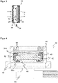
- figure 3 shows the adaptive lens of the reception optics 14 or the transmission optics 24 in an exemplary embodiment as a liquid lens 26 according to the electrowetting effect. This is only about the functional principle, the specific design and construction may vary. The mode of operation is explained using this liquid lens 26, but the invention also includes other adaptive lenses, for example those with a liquid chamber and a membrane covering it, the curvature of which is changed by pressure on the liquid, or lenses with a gel-like optically permeable material that through an actuator is mechanically deformed.
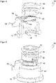
- the Figures 4 to 6 show a lens module 38 with an adaptive lens 40 in a sectional view, a cut three-dimensional view and a three-dimensional view from the outside.
- the adaptive lens 40 can be a liquid lens, as to figure 3 described, or use another principle to adjust the focal length.
- the adaptive lens 40 is accommodated in a module housing 42 with a base 44 and a side wall 46 .
- a corrugated spring 48 presses the adaptive lens 40 downwards against the floor 44.
- the corrugated spring 48 in turn is pressed from above by a press ring 50.
- An insulating element 52 is arranged between corrugated spring 48 and adaptive lens 40 .
- the components mentioned are designed cylindrically or as a ring and are in any case approximately shaped as a body of revolution around the optical axis.
- Electrodes 54a-b of the adaptive lens 40 are contacted by a connecting line 56 designed as a flexible line, so that the electrodes 54a-b can be controlled laterally from outside the lens module 38.
- a connecting line 56 designed as a flexible line, so that the electrodes 54a-b can be controlled laterally from outside the lens module 38.
- an optional resistor 58 is also shown on the connection line 56, which serves as a temperature sensor.
- the adaptive lens 40 is thus spring-loaded by the corrugated spring 48, ie it is pressed against the floor 44 with a defined force. It thus replaces the conventional tolerance-critical O-ring and avoids the associated disadvantages.
- the wave spring 48 is preferably made of metal and is, for example, a precision wave spring a ball bearing manufacturer. The advantage is that the characteristic curve of the corrugated spring 48 is almost linear and there are practically no fluctuations in the force exerted over the entire industrial temperature range. Electrical insulation between the electrodes 54a-b of the adaptive lens 40 is required for a metallic and thus, in contrast to a conventional O-ring, electrically conductive corrugated spring 48 .
- the insulation element 52 which is shaped as a ring and can also be used as an assembly aid.
- the thickness of the pressure ring 50 is preferably designed such that when the lens module is assembled, its end face is pressed flush with the module housing 42 and the correct force of the corrugated spring 48 on the adaptive lens is thus automatically set in the typical range ⁇ 10 N.
- the lens module 38 is placed on the connection piece 62 and pressed on via a multiturn spring 64 and thus held in position.
- the multiturn spring 64 is pressed against a front pane 66, for example of an optoelectronic sensor 10, or alternatively to the front pane 66, another element and is thereby tensioned.
- An optional protection against extraneous light or an extraneous light filter 68 can also be arranged in between.
Landscapes
- Physics & Mathematics (AREA)
- General Physics & Mathematics (AREA)
- Spectroscopy & Molecular Physics (AREA)
- Optics & Photonics (AREA)
- Engineering & Computer Science (AREA)
- General Engineering & Computer Science (AREA)
- Mechanical Engineering (AREA)
- Lens Barrels (AREA)
- Studio Devices (AREA)
- Camera Bodies And Camera Details Or Accessories (AREA)
- Mechanical Light Control Or Optical Switches (AREA)
- Prostheses (AREA)
- Optical Couplings Of Light Guides (AREA)
Applications Claiming Priority (1)
| Application Number | Priority Date | Filing Date | Title |
|---|---|---|---|
| DE102020125369.9A DE102020125369A1 (de) | 2020-09-29 | 2020-09-29 | Linsenmodul |
Publications (4)
| Publication Number | Publication Date |
|---|---|
| EP3974878A2 true EP3974878A2 (fr) | 2022-03-30 |
| EP3974878A3 EP3974878A3 (fr) | 2022-07-27 |
| EP3974878C0 EP3974878C0 (fr) | 2023-06-07 |
| EP3974878B1 EP3974878B1 (fr) | 2023-06-07 |
Family
ID=80442271
Family Applications (1)
| Application Number | Title | Priority Date | Filing Date |
|---|---|---|---|
| EP21189225.2A Active EP3974878B1 (fr) | 2020-09-29 | 2021-08-02 | Module de lentille |
Country Status (5)
| Country | Link |
|---|---|
| US (1) | US20220099866A1 (fr) |
| EP (1) | EP3974878B1 (fr) |
| JP (1) | JP2022056366A (fr) |
| CN (1) | CN114355606A (fr) |
| DE (1) | DE102020125369A1 (fr) |
Families Citing this family (1)
| Publication number | Priority date | Publication date | Assignee | Title |
|---|---|---|---|---|
| CN115015112A (zh) * | 2022-04-20 | 2022-09-06 | 华兴源创(成都)科技有限公司 | 一种缺陷检测装置和方法 |
Citations (5)
| Publication number | Priority date | Publication date | Assignee | Title |
|---|---|---|---|---|
| EP0098540A2 (fr) | 1982-07-08 | 1984-01-18 | Firma Carl Zeiss | Dispositif pour l'éclairage par transmission |
| US20060044455A1 (en) | 2004-09-02 | 2006-03-02 | Samsung Electro-Mechanics Co., Ltd. | Lens-positioning device of camera module |
| US7616388B2 (en) | 2006-04-13 | 2009-11-10 | Milestone Co., Ltd. | Image capture lens feeding device and method of assembly of same |
| JP4419417B2 (ja) | 2003-04-01 | 2010-02-24 | 株式会社ニコン | 像振れ補正が可能な光学機器およびカメラ用交換レンズ |
| US20130229617A1 (en) | 2012-03-04 | 2013-09-05 | Zoom Focus Eyewear LLC dba Superfocus LLC | Variable focus spectacles with bipolar lens units and front masking lenses |
Family Cites Families (34)
| Publication number | Priority date | Publication date | Assignee | Title |
|---|---|---|---|---|
| JPH07140367A (ja) * | 1993-11-19 | 1995-06-02 | Konica Corp | レンズ鏡胴 |
| KR100272328B1 (ko) * | 1993-12-22 | 2001-02-01 | 이중구 | 렌즈의 공기 간격 조절장치 |
| US7006141B1 (en) * | 1999-11-23 | 2006-02-28 | Panavision, Inc. | Method and objective lens for spectrally modifying light for an electronic camera |
| US7646544B2 (en) * | 2005-05-14 | 2010-01-12 | Batchko Robert G | Fluidic optical devices |
| EP1237362B1 (fr) * | 2001-02-28 | 2004-02-18 | Benjamin Gabel | Caméra vidéo et adaptateur pour caméra vidéo |
| EP1245373B8 (fr) * | 2001-03-27 | 2007-02-21 | Novartis AG | Assemblage de moules pour la fabrication d'une pluralité de lentilles de contact |
| JP2002320122A (ja) * | 2001-04-20 | 2002-10-31 | Konica Corp | 撮像装置 |
| WO2004086114A1 (fr) * | 2003-03-24 | 2004-10-07 | Koninklijke Philips Electronics N.V. | Appareil photo comprenant des moyens pour regler de facon precise la distance entre un objectif et un capteur d'images sous forme de puce |
| KR20060068611A (ko) * | 2004-12-16 | 2006-06-21 | 엘지전자 주식회사 | 화상 픽업 장치 |
| GB0702835D0 (en) * | 2007-02-14 | 2007-03-28 | Johnson Electric Sa | Lens module |
| JP2009216946A (ja) * | 2008-03-10 | 2009-09-24 | Olympus Imaging Corp | 撮影レンズユニットおよびデジタルカメラ |
| US8102611B2 (en) | 2008-09-26 | 2012-01-24 | Itt Manufacturing Enterprises, Inc. | Backlash reducing device for an objective lens assembly |
| US7905407B2 (en) * | 2008-11-18 | 2011-03-15 | Symbol Technologies, Inc. | Electro-optical lens mounting assembly and method in electro-optical readers |
| US8134116B2 (en) * | 2009-01-12 | 2012-03-13 | Cognex Corporation | Modular focus system for image based code readers |
| JP4402164B1 (ja) * | 2009-04-06 | 2010-01-20 | 株式会社オプトエレクトロニクス | 液体レンズ光学体及び光学的情報読取装置 |
| JP5875804B2 (ja) * | 2010-09-10 | 2016-03-02 | オリンパス株式会社 | レンズ鏡筒および撮像装置 |
| DE102011054072B4 (de) * | 2011-09-30 | 2013-08-29 | Qioptiq Photonics Gmbh & Co. Kg | Linsenhalterung für Flüssiglinsen sowie Dentalkamera mit einer in einer Linsenhalterung aufgenommenen Flüssiglinse |
| US9110293B2 (en) * | 2011-10-17 | 2015-08-18 | Manufacturing Techniques, Inc. | Prismatic image replication for obtaining color data from a monochrome detector array |
| US8947590B2 (en) | 2011-11-22 | 2015-02-03 | Cognex Corporation | Vision system camera with mount for multiple lens types |
| US11366284B2 (en) * | 2011-11-22 | 2022-06-21 | Cognex Corporation | Vision system camera with mount for multiple lens types and lens module for the same |
| EP2703862B1 (fr) * | 2012-09-04 | 2019-06-19 | CLAAS E-Systems GmbH | Objectif de caméra |
| CA2896241C (fr) * | 2012-12-26 | 2021-04-20 | Thorlabs, Inc. | Monture optique a faible distorsion sur le front de l'onde |
| KR20150054057A (ko) * | 2013-11-08 | 2015-05-20 | 자화전자(주) | 렌즈 구동용 엑츄에이터 및 이를 포함하는 카메라 렌즈 조립체 |
| US10288095B2 (en) * | 2014-09-22 | 2019-05-14 | Institut National D'optique | Mounting of an optical element in a barrel using a flexible ring |
| JP6951484B2 (ja) * | 2015-06-04 | 2021-10-20 | マクセル株式会社 | レンズユニットおよび車載カメラ |
| DE102017209391B4 (de) * | 2017-06-02 | 2021-07-15 | Bruker Optik Gmbh | Selbstzentrierende Linsenanordnung für eine transmittive, refraktive Optik |
| KR102552516B1 (ko) * | 2018-01-23 | 2023-07-11 | 엘지이노텍 주식회사 | 감지된 온도 정보를 이용하여 렌즈 곡률을 가변하는 렌즈 곡률 가변 장치, 이를 구비하는 카메라, 및 영상표시장치 |
| CN209375770U (zh) * | 2018-01-25 | 2019-09-10 | 台湾东电化股份有限公司 | 光学系统 |
| CN207965290U (zh) * | 2018-02-02 | 2018-10-12 | 杭州海康威视数字技术股份有限公司 | 一种镜头卡口固定结构及具有其的热成像设备 |
| JP2019164253A (ja) * | 2018-03-20 | 2019-09-26 | カンタツ株式会社 | 撮像レンズおよびカメラモジュール |
| TW202022411A (zh) * | 2018-10-09 | 2020-06-16 | 美商康寧公司 | 液態透鏡 |
| DE202018107124U1 (de) * | 2018-12-13 | 2020-03-18 | Sick Ag | Optoelektronischer Sensor |
| WO2020258327A1 (fr) * | 2019-06-28 | 2020-12-30 | 瑞声光学解决方案私人有限公司 | Lentille optique |
| US11719904B2 (en) * | 2020-05-29 | 2023-08-08 | Zebra Technologies Corporation | Optical arrangement for small size wide angle auto focus imaging lens for high resolution sensors |
-
2020
- 2020-09-29 DE DE102020125369.9A patent/DE102020125369A1/de not_active Withdrawn
-
2021
- 2021-08-02 EP EP21189225.2A patent/EP3974878B1/fr active Active
- 2021-08-12 US US17/400,369 patent/US20220099866A1/en not_active Abandoned
- 2021-08-25 JP JP2021137122A patent/JP2022056366A/ja active Pending
- 2021-09-18 CN CN202111101624.9A patent/CN114355606A/zh active Pending
Patent Citations (5)
| Publication number | Priority date | Publication date | Assignee | Title |
|---|---|---|---|---|
| EP0098540A2 (fr) | 1982-07-08 | 1984-01-18 | Firma Carl Zeiss | Dispositif pour l'éclairage par transmission |
| JP4419417B2 (ja) | 2003-04-01 | 2010-02-24 | 株式会社ニコン | 像振れ補正が可能な光学機器およびカメラ用交換レンズ |
| US20060044455A1 (en) | 2004-09-02 | 2006-03-02 | Samsung Electro-Mechanics Co., Ltd. | Lens-positioning device of camera module |
| US7616388B2 (en) | 2006-04-13 | 2009-11-10 | Milestone Co., Ltd. | Image capture lens feeding device and method of assembly of same |
| US20130229617A1 (en) | 2012-03-04 | 2013-09-05 | Zoom Focus Eyewear LLC dba Superfocus LLC | Variable focus spectacles with bipolar lens units and front masking lenses |
Also Published As
| Publication number | Publication date |
|---|---|
| CN114355606A (zh) | 2022-04-15 |
| JP2022056366A (ja) | 2022-04-08 |
| EP3974878A3 (fr) | 2022-07-27 |
| US20220099866A1 (en) | 2022-03-31 |
| EP3974878C0 (fr) | 2023-06-07 |
| DE102020125369A1 (de) | 2022-03-31 |
| EP3974878B1 (fr) | 2023-06-07 |
Similar Documents
| Publication | Publication Date | Title |
|---|---|---|
| EP2924477B1 (fr) | Dispositif optoélectronique et procédé de détection d'informations d'objets | |
| EP2924974B1 (fr) | Dispositif opto-électronique et procédé pour capturer des images nettes | |
| EP2924973B1 (fr) | Dispositif optoélectronique et son procédé de réglage | |
| DE102007007472A1 (de) | Linsenantriebsvorrichtung | |
| EP3280127A1 (fr) | Systeme de camera | |
| EP1845401B1 (fr) | Prodédé d'ajustement d'au moins un élément optique d'un capteur | |
| EP3974878B1 (fr) | Module de lentille | |
| EP1513094B1 (fr) | Dispositif de balayage | |
| WO2023134818A1 (fr) | Système optique et véhicule ayant au moins un système optique | |
| EP1698995B1 (fr) | Dispositif d'identification | |
| DE102006049799B4 (de) | Linsenverschiebevorrichtung | |
| DE202020105559U1 (de) | Linsenmodul | |
| DE102006059091B4 (de) | Mikrooptisches reflektierendes Bauelement und dessen Verwendung | |
| DE19621188B4 (de) | Optischer Sensor zur Bestimmung des Drehwinkels einer Drehachse | |
| DE4445087C1 (de) | Vorrichtung zur Temperaturkompensation | |
| DE102013225287A1 (de) | Bildaufnahmevorrichtung mit einer Verschiebeeinrichtung für ein Digitalmikroskop und Digitalmikroskop | |
| DE2512384C2 (de) | Feinfokussiereinrichtung für das Objektiv eines optischen Instrumentes | |
| DE102012002853B4 (de) | Fokussiervorrichtung mit einem ein nichtlineares Getriebe aufweisenden Phasenplattensystem | |
| DE102018132699A1 (de) | System und Verfahren zur Driftverringerung bei einer Verstelllinse eines Sichtsystems | |
| DE102004018106B4 (de) | Hochgenauer optischer Positionsdetektor für Galvanometer-Drehantiebe | |
| DE102007056643B3 (de) | Optischer Sensor | |
| DE102023119914A1 (de) | Einrichtung zur Bewegung einer Optik und Laserbearbeitungsvorrichtung | |
| WO2026068649A1 (fr) | Dispositif de caméra et procédé de production d'un dispositif de caméra | |
| DE102024100404A1 (de) | Optoelektronische einrichtung | |
| DE202024100064U1 (de) | Optoelektronische Einrichtung |
Legal Events
| Date | Code | Title | Description |
|---|---|---|---|
| PUAI | Public reference made under article 153(3) epc to a published international application that has entered the european phase |
Free format text: ORIGINAL CODE: 0009012 |
|
| STAA | Information on the status of an ep patent application or granted ep patent |
Free format text: STATUS: THE APPLICATION HAS BEEN PUBLISHED |
|
| AK | Designated contracting states |
Kind code of ref document: A2 Designated state(s): AL AT BE BG CH CY CZ DE DK EE ES FI FR GB GR HR HU IE IS IT LI LT LU LV MC MK MT NL NO PL PT RO RS SE SI SK SM TR |
|
| PUAL | Search report despatched |
Free format text: ORIGINAL CODE: 0009013 |
|
| AK | Designated contracting states |
Kind code of ref document: A3 Designated state(s): AL AT BE BG CH CY CZ DE DK EE ES FI FR GB GR HR HU IE IS IT LI LT LU LV MC MK MT NL NO PL PT RO RS SE SI SK SM TR |
|
| RIC1 | Information provided on ipc code assigned before grant |
Ipc: G01J 1/04 20060101ALI20220620BHEP Ipc: F16F 1/32 20060101ALI20220620BHEP Ipc: G02B 3/14 20060101AFI20220620BHEP |
|
| STAA | Information on the status of an ep patent application or granted ep patent |
Free format text: STATUS: REQUEST FOR EXAMINATION WAS MADE |
|
| 17P | Request for examination filed |
Effective date: 20220729 |
|
| RBV | Designated contracting states (corrected) |
Designated state(s): AL AT BE BG CH CY CZ DE DK EE ES FI FR GB GR HR HU IE IS IT LI LT LU LV MC MK MT NL NO PL PT RO RS SE SI SK SM TR |
|
| GRAP | Despatch of communication of intention to grant a patent |
Free format text: ORIGINAL CODE: EPIDOSNIGR1 |
|
| STAA | Information on the status of an ep patent application or granted ep patent |
Free format text: STATUS: GRANT OF PATENT IS INTENDED |
|
| INTG | Intention to grant announced |
Effective date: 20221028 |
|
| GRAS | Grant fee paid |
Free format text: ORIGINAL CODE: EPIDOSNIGR3 |
|
| GRAA | (expected) grant |
Free format text: ORIGINAL CODE: 0009210 |
|
| STAA | Information on the status of an ep patent application or granted ep patent |
Free format text: STATUS: THE PATENT HAS BEEN GRANTED |
|
| AK | Designated contracting states |
Kind code of ref document: B1 Designated state(s): AL AT BE BG CH CY CZ DE DK EE ES FI FR GB GR HR HU IE IS IT LI LT LU LV MC MK MT NL NO PL PT RO RS SE SI SK SM TR |
|
| REG | Reference to a national code |
Ref country code: GB Ref legal event code: FG4D Free format text: NOT ENGLISH |
|
| REG | Reference to a national code |
Ref country code: CH Ref legal event code: EP Ref country code: AT Ref legal event code: REF Ref document number: 1576805 Country of ref document: AT Kind code of ref document: T Effective date: 20230615 |
|
| REG | Reference to a national code |
Ref country code: DE Ref legal event code: R096 Ref document number: 502021000793 Country of ref document: DE |
|
| U01 | Request for unitary effect filed |
Effective date: 20230607 |
|
| U07 | Unitary effect registered |
Designated state(s): AT BE BG DE DK EE FI FR IT LT LU LV MT NL PT SE SI Effective date: 20230612 |
|
| U20 | Renewal fee for the european patent with unitary effect paid |
Year of fee payment: 3 Effective date: 20230817 |
|
| REG | Reference to a national code |
Ref country code: LT Ref legal event code: MG9D |
|
| PG25 | Lapsed in a contracting state [announced via postgrant information from national office to epo] |
Ref country code: NO Free format text: LAPSE BECAUSE OF FAILURE TO SUBMIT A TRANSLATION OF THE DESCRIPTION OR TO PAY THE FEE WITHIN THE PRESCRIBED TIME-LIMIT Effective date: 20230907 Ref country code: ES Free format text: LAPSE BECAUSE OF FAILURE TO SUBMIT A TRANSLATION OF THE DESCRIPTION OR TO PAY THE FEE WITHIN THE PRESCRIBED TIME-LIMIT Effective date: 20230607 |
|
| PG25 | Lapsed in a contracting state [announced via postgrant information from national office to epo] |
Ref country code: RS Free format text: LAPSE BECAUSE OF FAILURE TO SUBMIT A TRANSLATION OF THE DESCRIPTION OR TO PAY THE FEE WITHIN THE PRESCRIBED TIME-LIMIT Effective date: 20230607 Ref country code: HR Free format text: LAPSE BECAUSE OF FAILURE TO SUBMIT A TRANSLATION OF THE DESCRIPTION OR TO PAY THE FEE WITHIN THE PRESCRIBED TIME-LIMIT Effective date: 20230607 Ref country code: GR Free format text: LAPSE BECAUSE OF FAILURE TO SUBMIT A TRANSLATION OF THE DESCRIPTION OR TO PAY THE FEE WITHIN THE PRESCRIBED TIME-LIMIT Effective date: 20230908 |
|
| PG25 | Lapsed in a contracting state [announced via postgrant information from national office to epo] |
Ref country code: SK Free format text: LAPSE BECAUSE OF FAILURE TO SUBMIT A TRANSLATION OF THE DESCRIPTION OR TO PAY THE FEE WITHIN THE PRESCRIBED TIME-LIMIT Effective date: 20230607 |
|
| PG25 | Lapsed in a contracting state [announced via postgrant information from national office to epo] |
Ref country code: IS Free format text: LAPSE BECAUSE OF FAILURE TO SUBMIT A TRANSLATION OF THE DESCRIPTION OR TO PAY THE FEE WITHIN THE PRESCRIBED TIME-LIMIT Effective date: 20231007 |
|
| PG25 | Lapsed in a contracting state [announced via postgrant information from national office to epo] |
Ref country code: SM Free format text: LAPSE BECAUSE OF FAILURE TO SUBMIT A TRANSLATION OF THE DESCRIPTION OR TO PAY THE FEE WITHIN THE PRESCRIBED TIME-LIMIT Effective date: 20230607 Ref country code: SK Free format text: LAPSE BECAUSE OF FAILURE TO SUBMIT A TRANSLATION OF THE DESCRIPTION OR TO PAY THE FEE WITHIN THE PRESCRIBED TIME-LIMIT Effective date: 20230607 Ref country code: RO Free format text: LAPSE BECAUSE OF FAILURE TO SUBMIT A TRANSLATION OF THE DESCRIPTION OR TO PAY THE FEE WITHIN THE PRESCRIBED TIME-LIMIT Effective date: 20230607 Ref country code: IS Free format text: LAPSE BECAUSE OF FAILURE TO SUBMIT A TRANSLATION OF THE DESCRIPTION OR TO PAY THE FEE WITHIN THE PRESCRIBED TIME-LIMIT Effective date: 20231007 Ref country code: CZ Free format text: LAPSE BECAUSE OF FAILURE TO SUBMIT A TRANSLATION OF THE DESCRIPTION OR TO PAY THE FEE WITHIN THE PRESCRIBED TIME-LIMIT Effective date: 20230607 |
|
| PG25 | Lapsed in a contracting state [announced via postgrant information from national office to epo] |
Ref country code: PL Free format text: LAPSE BECAUSE OF FAILURE TO SUBMIT A TRANSLATION OF THE DESCRIPTION OR TO PAY THE FEE WITHIN THE PRESCRIBED TIME-LIMIT Effective date: 20230607 |
|
| REG | Reference to a national code |
Ref country code: DE Ref legal event code: R097 Ref document number: 502021000793 Country of ref document: DE |
|
| PG25 | Lapsed in a contracting state [announced via postgrant information from national office to epo] |
Ref country code: MC Free format text: LAPSE BECAUSE OF FAILURE TO SUBMIT A TRANSLATION OF THE DESCRIPTION OR TO PAY THE FEE WITHIN THE PRESCRIBED TIME-LIMIT Effective date: 20230607 |
|
| PG25 | Lapsed in a contracting state [announced via postgrant information from national office to epo] |
Ref country code: MC Free format text: LAPSE BECAUSE OF FAILURE TO SUBMIT A TRANSLATION OF THE DESCRIPTION OR TO PAY THE FEE WITHIN THE PRESCRIBED TIME-LIMIT Effective date: 20230607 |
|
| PLBE | No opposition filed within time limit |
Free format text: ORIGINAL CODE: 0009261 |
|
| STAA | Information on the status of an ep patent application or granted ep patent |
Free format text: STATUS: NO OPPOSITION FILED WITHIN TIME LIMIT |
|
| 26N | No opposition filed |
Effective date: 20240308 |
|
| REG | Reference to a national code |
Ref country code: IE Ref legal event code: MM4A |
|
| PG25 | Lapsed in a contracting state [announced via postgrant information from national office to epo] |
Ref country code: IE Free format text: LAPSE BECAUSE OF NON-PAYMENT OF DUE FEES Effective date: 20230802 |
|
| PG25 | Lapsed in a contracting state [announced via postgrant information from national office to epo] |
Ref country code: IE Free format text: LAPSE BECAUSE OF NON-PAYMENT OF DUE FEES Effective date: 20230802 |
|
| U20 | Renewal fee for the european patent with unitary effect paid |
Year of fee payment: 4 Effective date: 20240814 |
|
| PG25 | Lapsed in a contracting state [announced via postgrant information from national office to epo] |
Ref country code: CY Free format text: LAPSE BECAUSE OF FAILURE TO SUBMIT A TRANSLATION OF THE DESCRIPTION OR TO PAY THE FEE WITHIN THE PRESCRIBED TIME-LIMIT; INVALID AB INITIO Effective date: 20210802 |
|
| PG25 | Lapsed in a contracting state [announced via postgrant information from national office to epo] |
Ref country code: HU Free format text: LAPSE BECAUSE OF FAILURE TO SUBMIT A TRANSLATION OF THE DESCRIPTION OR TO PAY THE FEE WITHIN THE PRESCRIBED TIME-LIMIT; INVALID AB INITIO Effective date: 20210802 |
|
| U20 | Renewal fee for the european patent with unitary effect paid |
Year of fee payment: 5 Effective date: 20250826 |
|
| PGFP | Annual fee paid to national office [announced via postgrant information from national office to epo] |
Ref country code: GB Payment date: 20250822 Year of fee payment: 5 |
|
| PGFP | Annual fee paid to national office [announced via postgrant information from national office to epo] |
Ref country code: CH Payment date: 20250901 Year of fee payment: 5 |
|
| PG25 | Lapsed in a contracting state [announced via postgrant information from national office to epo] |
Ref country code: TR Free format text: LAPSE BECAUSE OF FAILURE TO SUBMIT A TRANSLATION OF THE DESCRIPTION OR TO PAY THE FEE WITHIN THE PRESCRIBED TIME-LIMIT Effective date: 20230607 |