EP3975149A2 - System und verfahren zur erfassung von schäden in gebäuden - Google Patents
System und verfahren zur erfassung von schäden in gebäuden Download PDFInfo
- Publication number
- EP3975149A2 EP3975149A2 EP21197833.3A EP21197833A EP3975149A2 EP 3975149 A2 EP3975149 A2 EP 3975149A2 EP 21197833 A EP21197833 A EP 21197833A EP 3975149 A2 EP3975149 A2 EP 3975149A2
- Authority
- EP
- European Patent Office
- Prior art keywords
- conductive element
- resistance
- electronic device
- detection system
- branches
- Prior art date
- Legal status (The legal status is an assumption and is not a legal conclusion. Google has not performed a legal analysis and makes no representation as to the accuracy of the status listed.)
- Pending
Links
Images




Classifications
-
- G—PHYSICS
- G08—SIGNALLING
- G08B—SIGNALLING SYSTEMS, e.g. PERSONAL CALLING SYSTEMS; ORDER TELEGRAPHS; ALARM SYSTEMS
- G08B21/00—Alarms responsive to a single specified undesired or abnormal condition and not otherwise provided for
- G08B21/18—Status alarms
- G08B21/20—Status alarms responsive to moisture
-
- G—PHYSICS
- G01—MEASURING; TESTING
- G01M—TESTING STATIC OR DYNAMIC BALANCE OF MACHINES OR STRUCTURES; TESTING OF STRUCTURES OR APPARATUS, NOT OTHERWISE PROVIDED FOR
- G01M3/00—Investigating fluid-tightness of structures
- G01M3/02—Investigating fluid-tightness of structures by using fluid or vacuum
- G01M3/04—Investigating fluid-tightness of structures by using fluid or vacuum by detecting the presence of fluid at the leakage point
- G01M3/16—Investigating fluid-tightness of structures by using fluid or vacuum by detecting the presence of fluid at the leakage point using electric detection means
- G01M3/165—Investigating fluid-tightness of structures by using fluid or vacuum by detecting the presence of fluid at the leakage point using electric detection means by means of cables or similar elongated devices, e.g. tapes
-
- G—PHYSICS
- G08—SIGNALLING
- G08B—SIGNALLING SYSTEMS, e.g. PERSONAL CALLING SYSTEMS; ORDER TELEGRAPHS; ALARM SYSTEMS
- G08B25/00—Alarm systems in which the location of the alarm condition is signalled to a central station, e.g. fire or police telegraphic systems
- G08B25/01—Alarm systems in which the location of the alarm condition is signalled to a central station, e.g. fire or police telegraphic systems characterised by the transmission medium
- G08B25/018—Sensor coding by detecting magnitude of an electrical parameter, e.g. resistance
Definitions
- the present invention relates to the field of loss detection systems in buildings.
- water leak detection systems comprising at least two elongated conductive elements arranged in parallel and extending between a first end and a second end.
- a first conductive element is electrically powered by an electronic device with a voltage V1.
- the electronic device is able to measure the voltage on the second elongated conductive element.
- These conductive elements are arranged directly on a wall or on a support, permeable, itself fixed to a wall.
- One solution for locating the leak is to multiply the number of detection systems to square the wall/surface and thus better locate the leak.
- Another solution consists in having a detection system comprising a plurality of conductive elements extending parallel horizontally and a plurality of conductive elements extending parallel vertically.
- conductive elements extending horizontally are powered by the electronic device and the electronic device measures the voltage of the vertically extending conductive elements.
- the present invention therefore proposes to solve these drawbacks by providing a detection system capable of detecting a disaster such as a water leak over a larger area while being capable of locating this disaster.
- the invention relates to a system for detecting the presence of liquid water which comprises a first and a second conductive element, each conductive element comprising a main portion from which at least two branches extend, the number of branches being identical between the first element and the second conductive element, the conductive elements being arranged so that the branches of the first conductive element and the branches of the second conductive element are parallel to each other, characterized in that the first conductive element is supplied electrically by an electronic device, the electronic device being capable of measuring the voltage of the second conductor.
- the first element and the second conductive element have the same resistance per meter, the main portion of the second conductor comprising, between each branch, a resistance Ri.
- the first element and the second conductive element have a different resistance per meter.
- the resistance per meter (p1) of the first conductive element and the resistance per meter (p2) of the second conductive element have a value such that the following inequality is verified: ⁇ 1 ⁇ ⁇ 2 ⁇ D + ⁇ L / D ⁇ ⁇ L
- the value of the resistances Ri solves the following formula: laughed > 2 ⁇ ⁇ 1 ⁇ Lmax With p1 the resistance per electric meter ( ⁇ /m) of the conductive elements and Lmax the maximum distance of the secondary branches, these resistances Ri all having the same value.
- the main portion of the first conductive element comprises a first segment connected to the electronic device and extending parallel to the main portion of the second conductive element, a second segment extending parallel to the secondary branch of the second conductive element furthest remote from the electronic device and used as a secondary branch of the first conductive element farthest from the electronic device and a third segment extending parallel to the first segment, the secondary branches of the first conductive element extending from said third segment.
- the detection system comprises insulating strips arranged on the first conductive element facing the ends of the secondary branches of the second conductive element.
- the invention further relates to a system for detecting disasters, such as water leaks, which comprises a first and a second conductive element extending parallel in a first direction and a second direction perpendicular to the first direction, characterized in that that the first conductive element is electrically powered by an electronic device, the electronic device being able to measure the voltage of the second conductive element.
- the first conductive element and the second conductive element are arranged on a support.
- the support can be cut according to the position and the arrangement of the first and of the second conductive element.
- said support comprises at least one membrane or a plate on which the first conductive element and the second conductive element are arranged.
- said support comprises two membranes between which the first conductive element and the second conductive element are arranged.
- At least one membrane comprises a sheet or a sheet of sheets.
- each membrane comprises a sheet or a sheet of sheets.
- At least one membrane is permeable to water.
- the invention further relates to a method for detecting the presence of liquid water in a building equipped with a detection system according to the invention, characterized in that it consists in detecting an increase in potential in the second conductive element .
- the invention further relates to a method for detecting the presence of liquid water in a building equipped with a detection system according to the invention, characterized in that it comprises a location step consisting in, by means of of the electronic device, to determine a resistance from the measured voltage, said electronic device being able to perform calculations using said measured resistance and the resistance per meter of each conductive element to arrive at a length representative of the location.
- the invention further relates to a method for detecting a water leak in a building equipped with a detection system, characterized in that it comprises a location step consisting, via the electronic device, in determining a resistance from the measured voltage, this resistance being broken down into a first part whose value is equal to a multiple of the value of resistance Ri and a second part whose value depends on the resistance per meter of the secondary branches, said electronic device being capable of making calculations using said measured resistance, the value of resistance Ri and the resistance per meter of each conductive element to arrive at a length representative of the location.
- the first part of the resistance resulting from the measured voltage is representative of the secondary branch on which the leak is detected, the second part being representative of the position on the secondary branch.
- the invention further relates to a computer program comprising instructions for the execution of all or part of the steps of a method according to the invention when said program is executed by a computer.
- the invention relates to a wall which at least one detection system D according to the invention.
- This wall is positioned vertically in the case of a wall or partition or in the case of a roof, horizontally or inclined.
- This detection system D comprises an electronic device 3 and conductive elements. These conductive elements can be metal wires such as, for example, tin or copper or stainless steel.
- the conductive elements are paper or cardboard strips comprising a conductive material.
- the strips can be coated or impregnated with a conductive material, for example carbon.
- These conductive elements can also be in the form of an ink or a conductive paste which would be applied by printing, jet printing or screen printing.
- conductive elements are preferably arranged on a support S.
- This support may be in the form of a membrane M made of a permeable material (which absorbs water) or impermeable to water or vapor. water or in the form of a plate, this plate possibly being made of plaster or other (for example cardboard) as visible on figure 10 .
- the support S can also be in the form of a first membrane M1 and a second membrane M2.
- the first membrane M1 is made of a permeable material while the second membrane M2 is made of a permeable or impermeable material.
- the second membrane M2 comprises a sheet or a sheet of sheets.
- the two conductive elements are arranged between the first membrane M1 and the second membrane M2 as visible in figure 11 .
- the membrane material M can, for example, be in the form of a polymer, a sheet of polymers, kraft paper, non-woven glass veil, cardboard etc.
- this support S is installed on the wall in several ways. Either the membrane M is permeable and said membrane M is in contact with the wall or the membrane M is impermeable and it is the conductive elements which are in contact with the wall.
- a support S with a first membrane M1 and a second membrane M2 it is arranged so that the first membrane M1, permeable, is in contact with the wall.
- the conductive elements are arranged on one of the faces of the plasterboard. This face carrying the conductive elements is arranged so that the conductive elements are facing or not the wall on which the plate is fixed.
- the detection system D comprises two conductive elements: a first conductive element 1 and a second conductive element 2. These conductive elements 1, 2 are arranged to extend in parallel. These conductive elements 1, 2 have a crenellated shape. Such a shape makes it possible to have conductive elements 1, 2 which extend along a first direction and a second direction. In our case of a detection system D for a wall, the first direction is a direction parallel to the ground plane while the second direction is a direction orthogonal to the ground plane.
- the two conductive elements 1, 2 have a resistance per meter ( ⁇ /m) which may be identical or different.
- the spacing between the two conductive elements 1, 2 is between 0.5 and 15 cm.
- the operation of this first embodiment consists in sending a voltage, for example 5V, into a first conductive element 1 via the electronic device 3. Normally, a non-zero voltage is measured in this first conductive element 1 and a voltage zero (or almost zero) is measured in the second conductive element 2. These voltage measurements are carried out, in the invention, with respect to the ground of the electronic device 3.
- a voltage for example 5V
- This conduction causes the current to flow from the first conductive element 1 powered by a non-zero voltage to the second conductive element 2 which is normally not powered by an electric voltage.
- the electronic device 3 to which the second conductive element 2 is connected then receives a voltage. This voltage is measured by the electronic device 3 and processed to provide information.
- the electronic device 3 is provided with a calculation unit (not shown) to carry out this processing of the voltage measurements.
- the electronic device 3 can then comprise a computer program making it possible to carry out the detection.
- the voltage is zero so the electronic device 3 processes this voltage and determines that there are no claims.
- this non-zero voltage signifies the presence of a disaster and the electronic device 3 can send a signal with the information that a disaster is present.
- This signal can be sent to an alarm module with audible or visual function or to a portable communication terminal.
- the electronic device 3 measuring the voltage at the second conductive element 2 is capable of locating said disaster.
- the electronic device 3 comprises a location module making it possible to locate the incident.
- a first embodiment of this location module consists in using a voltage divider. This location is based on the principle of calculating the resistance of the conductive elements 1, 2.
- the conductive elements 1, 2 have a resistance per meter such that for a conductive element with a resistance per meter of 200 ⁇ /m, a measured resistance of 400 ⁇ means a length of 2m.
- the divider module consists of two resistors in series: a resistor R2 representative of the resistance of the conductive elements 1, 2 and a known resistor R1. As seen on the figure 13
- R2 (Ve ⁇ Vs) ⁇ R1 / Vs with Ve the voltage applied to the first conductive element, Vs the measured voltage and R1 the internal resistance.
- the value of resistance R2 is representative of the cumulative length of the first conductive element 1 and of the second conductive element 2 up to the conduction point. As the first conductive element 1 and the second conductive element 2 extend in parallel, it is necessary to divide the result by two to determine the location.
- each location is based on an identical principle. Indeed, each location has a specific resistance value resulting from the resistance of the first conductive element 1 added to the resistance of the second conductive element 2.
- the electronic device 3 is then able to make calculations for, from a value of measured resistance, find the location.
- a Wheatstone bridge to measure a resistance variation or an assembly with an operational amplifier in transimpedance mode to measure a current on the second conductive element 2 can also be used.
- the electronic device 3 is designed to incorporate, in a memory unit 31, the slotted geometry of the conductive elements 1, 2. This geometry also incorporates the dimensions of the slot. This integration of the dimensions of the slot allows the electronic device 3 to provide a precise location. Indeed, by knowing the geometry of the slot, that is to say its width and its height, it is possible for an algorithm to determine the precise location of the disaster.
- this first embodiment it is possible to adapt the detection system D.
- This adaptation is done by modifying the length of the support S on which the conductive elements 1, 2 are arranged.
- the slotted pattern allows, for each slot, to have a determined length and resistance.
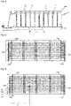
- the detection system D comprises a first conductive element 10 and a second conductive element 20.
- Each conductive element 10, 20 comprises a main portion 11, 21 extending parallel to the plane of the ground. From this main portion 11, 21, a plurality of secondary branches 13, 23 extend. These branches 13, 23 extend, preferably, perpendicular to the main portion 11, 21.
- Each conductive element 10, 20 thus takes the form of a comb.
- the first conductive element 10 and the second conductive element 20 are arranged to have the same number of secondary branches 13, 23. These combs are arranged so that the secondary branches 13 of the first conductive element 10 and the secondary branches 23 of the second conductive element 20 face each other and are parallel to each other. This makes it possible to have pairs of branches composed of a secondary branch 13 of the first conductive element 10 and of a secondary branch 23 of the second conductive element 20.
- the combs will be arranged so that the first secondary branch 13 of the first conductive element 10 is parallel to the first secondary branch 23 of the second conductive element 20. This forms a first pair of branches.
- the second secondary branch 13 of the first conductive element 10 is parallel to the second secondary branch 23 of the second conductive element 20.
- the third secondary branch 13 of the first conductive element 10 is parallel to the third secondary branch 23 of the second conductive element 20.
- the detection of a disaster is equivalent to that of the first embodiment.
- the first conductive element 10 is powered by a non-zero voltage via the electronic device 3 while the second conductive element 20 is not powered by a voltage, this second conductive element 20 therefore has a zero (or almost zero) voltage. normally.
- the location of the loss uses a resistance per meter of the first conductive element 10 different from the resistance per meter of the second conductive element 20. This different resistance per meter makes it possible to measure a specific voltage.
- This configuration results in a specific voltage range for each pair of secondary branches 13, 23.
- This voltage range is due to the fact that each pair of secondary branches 13, 23 has its own specific resistance range.
- On the picture 3 one can see conduction points A, B, C and D on two pairs of secondary branches 13, 23.
- the choice of different resistances per meter allows the resistance measured at point A to be different from that measured at point B and that the resistance measured at point B is different than that measured at point C.
- the conductive elements 10, 20 are arranged to allow adjustment in height.
- the first conductive element 10 is provided with insulating strips 15. These insulating strips 15 are glued or fixed on the support S supporting the first conductive element 10 and have a substantially rectangular shape. These insulating strips 15 are arranged so that the length of these strips 15 extends perpendicular to the main portion 11 of the first conductive element 10, the width of the strips 15 therefore extends parallel to the main portion 11 of the first conductive element 10.
- Each insulating strip 15 thus comprises two opposite sides extending parallel to the main portion 11: an outer side and an inner side, the inner side being closest to the second conductive element 20.
- the insulating strips 15 are thus placed so that the inner sides of the insulating strips 15 extend along the same axis. These insulating strips 15 are arranged close to each secondary branch 13 of the first conductive element 10, facing the ends of the secondary branches 23 of the second conductive element 20.
- the insulating strips 15 are dimensioned so that the length between the main portion 11 of the first conductive element 10 and the inner side is identical to the length between the end of the secondary branches 13 of the first conductive element 10 and the main portion 21 of the second element. driver 20.
- These strips 15 are used to facilitate the cutting of the support S on which the conductive elements 10, 20 are arranged. Indeed, it may be necessary for the operator to have to adjust the height of the detection system D in order to adapt to the wall on which it will be placed. It is nevertheless desired to maintain proper operation of said detection system D.
- a first part pa carries the main portion 11 of the first conductive element 10 as well as a fraction of the secondary branches 13 of the first element.
- the other part pb carries all of the second conductive element 20 as well as the rest of the secondary branches 13 of the first conductive element 10.
- This arrangement allows the operator to make a second cut at the second part pb. This cutting tends to reduce the length of the secondary branches 23 of the second conductive element 20 and of the rest of the secondary branches 13 of the first conductive element 10.
- a third step the operator will fix the two parts pa, pb together using fixing means such as glue or staples or adhesive tape.
- This fixing operation is done by adjusting the position of the parts to make the fractions of the secondary branches 13 of the first conductive element 10 of the first part pa coincide with the rest of the secondary branches 13 of said first conductive element 10.
- the insulating strips 15 then make it possible to prevent the ends of the secondary branches 23 of the second conductive element 20 from coming into contact with the first conductive element 10.
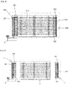
- the first conductive element 100 and the second conductive element 200 are in the form of combs. It is understood by this that the first conductive element 100 and the second conductive element 200 comprise a main portion 101, 201 from which secondary branches 103, 203 extend. These secondary branches 103, 203 extend parallel to the main portion 101, 201. In this third embodiment, the main portion 101, 201 of each perpendicular element extends perpendicular to the ground plane to be arranged vertically.
- the second conductive element 200 further comprises a plurality of resistors Ri.
- These resistors Ri are conventional electronics resistors or also be in the form of strips coated/impregnated with carbon black to have the right electrical resistance.
- These resistors Ri have an identical value and are arranged on the main portion 201.
- the number of resistors Ri is such that there is a resistor associated with each secondary branch 203 of the second conductive element 200.
- the first resistor R1 is arranged between the point of the electronic device 3 and the first secondary branch 203, the closest to the point of connection to the electronic device 3.
- the following resistors Ri are arranged between two secondary branches 203.
- the resistivity of the first conductive element 100 is identical to the resistivity of the second conductive element 200.
- the principle of this third embodiment is based on vertical and horizontal detection based on the resistance value measured.
- a divider bridge is used to measure a resistance resulting from conduction between a secondary branch 103 of the first conductive element 100 and a secondary branch 203 of the second conductive element 200.
- the voltage sent by the electronic device 3 in the first conductive element 100 is transmitted to the second conductive element 200 and measured by the electronic device 3.
- the fact of having secondary branches forming a comb means that for each branch of the comb, a range of voltage and therefore of resistance is possible.
- the electronic device 3 is based on a resistance calculation.
- the resistors Ri act as terminals between each branch of the comb. For example, if the resistances Ri have a value of 100, then a conduction to the first branch will have a value between 100 and 200: 100 being the value of the resistance R1 between the first branch and the electronic device and 200 being the value resistance R2 between the second branch and the electronic device 3.
- the value p1 of the resistance per meter ( ⁇ /m) of the conductive elements is used.
- the measured resistance value can be broken down into two parts: the first part which is a multiple of the value Ri which corresponds to the vertical position and a second part which corresponds to the length Li between the conduction point and the main portion 201 of the second conductive element 200.
- the electronic device 3 is capable of breaking down the resistance value measured into a first part which is a multiple of the value Ri which corresponds to the vertical position and a second part which corresponds to the length Li between the conduction point and the main portion of the second conductive element.
- the electronic device 3 uses the value of the electrical resistivity p1 ( ⁇ /m) of the conductive elements. Knowing this electrical resistivity and the value of the second part of the resistance measured, the device electronics 3 is capable of determining the distance from the conduction point, this distance being representative of the horizontal position.
- the detection system D is capable of precisely locating a water leak causing conduction between the first conductive element 100 and the second conductive element 200.
- the conductive elements 100, 200 are arranged to be compacted/assembled at the level of the connection with the electronic device.
- the comb configuration means that the main portion 101 of the first conductive element 100 and the main portion 201 of the second conductive element 200 are opposed. This configuration therefore requires having a main portion which has a greater length to connect to the electronic device, ideally the main portion 101 of the first conductive element 100 is the extended portion.
- the main portion 101 of the first conductive element 100 is arranged to comprise three segments.
- the first segment 101a is the segment connected to the electronic device 3 which extends parallel to the main portion 201 of the second connector element 200, that is to say the portion equipped with resistors Ri.
- a second segment 101b of this first conductive element 100 extends parallel to the secondary branches 103 of the second conductive element 200.
- this second segment extends parallel to the secondary branch 203 of the second conductive element 200 furthest from the electronic device.
- this second segment 101b acts as a secondary branch 103 of the first conductive element 100.
- This secondary branch 103 is associated with the secondary branch 203 of the second conductive element 200 furthest from the electronic device.
- a third and last segment 101c extends parallel to the first segment.
- This third segment 101c is the segment from which the other secondary branches 103 extend.
- This configuration is advantageous because it makes it possible to use a secondary branch 103 of the first conductive element 100 to bring the voltage delivered by the electronic device 3 to the other secondary branches.
- the detection system D is arranged so that the support S on which the conductive elements are placed is adaptable.
- the support S is divided into at least 3 portions: an initial portion P1, at least one intermediate portion P2 and a final portion P3.
- the initial portion P1 comprises the main portion 201 of the second conductive element 200, including the resistors Ri and fragments of the secondary branches 203 extending from this main portion 201.
- the final portion P3 comprises the main portion 101 of the first conductive element 100 and fragments of the secondary branches 103 extending from this main portion 101.
- An intermediate portion P2 comprises a plurality of sections. These sections are constituent elements of the secondary branches. Thus, half of the sections are components of the secondary branches 103 of the first conductive element 100 and the other half of the sections are components of the secondary branches 203 of the second conductive element 200.
- sections P1, P2, P3 are arranged to, when assembling the intermediate portion with an intermediate and/or final and/or initial portion, be aligned with the sections and/or fragments of secondary branches of the same conductive element.
- the initial portion P1 comprises the main portion of the second conductive element, including the resistors Ri and fragments of the secondary branches extending from this main portion and the first segment connected to the device electronic.
- the final portion P3 comprises the main portion of the first conductive element and fragments of the secondary branches extending from this main portion.
- An intermediate portion P2 comprises a plurality of sections. These sections are constituent elements of the secondary branches. Thus, half of the sections are constituent elements of the secondary branches of the first conductive element and the other half of the sections are constituent elements of the secondary branches of the second conductive element. One of the two sections located at the high and low ends of the intermediate portion serves as a second segment for the first conductive element. Indeed, the arrangement of the secondary branches and the identical electrical resistivity for the two conductive elements allows the intermediate portion to have no direction, which allows simplified installation.
- the sections P1, P2, P3 are arranged to, when assembling the intermediate portion with an intermediate and/or final and/or initial portion, be aligned with the sections and/or fragments of secondary branches of the same element driver.
- This third embodiment is that it is possible to adjust the size of the detection system in two dimensions. Indeed, it becomes possible to cut the intermediate and final and initial portions so as to reduce the number of branches. But it is also possible to cut the intermediate portion(s) in a direction perpendicular to that of the branches in order to adjust the length of the detection system.
- the present invention is not limited to the example illustrated but is susceptible to various variants and modifications which will become apparent to those skilled in the art.
- the conductive elements it is also possible for the conductive elements to be arranged directly on a wall to be equipped. This wall is capable of absorbing water so that the water can allow electrical conduction between the conductive elements.
Landscapes
- Physics & Mathematics (AREA)
- General Physics & Mathematics (AREA)
- Business, Economics & Management (AREA)
- Emergency Management (AREA)
- Examining Or Testing Airtightness (AREA)
Applications Claiming Priority (1)
| Application Number | Priority Date | Filing Date | Title |
|---|---|---|---|
| FR2009714A FR3114433A1 (fr) | 2020-09-24 | 2020-09-24 | système de détection de sinistres dans les bâtiments |
Publications (2)
| Publication Number | Publication Date |
|---|---|
| EP3975149A2 true EP3975149A2 (de) | 2022-03-30 |
| EP3975149A3 EP3975149A3 (de) | 2022-08-17 |
Family
ID=74183279
Family Applications (1)
| Application Number | Title | Priority Date | Filing Date |
|---|---|---|---|
| EP21197833.3A Pending EP3975149A3 (de) | 2020-09-24 | 2021-09-20 | System und verfahren zur erfassung von schäden in gebäuden |
Country Status (2)
| Country | Link |
|---|---|
| EP (1) | EP3975149A3 (de) |
| FR (1) | FR3114433A1 (de) |
Family Cites Families (4)
| Publication number | Priority date | Publication date | Assignee | Title |
|---|---|---|---|---|
| US6639517B1 (en) * | 2002-09-30 | 2003-10-28 | James Chapman | Leak detection mat and system |
| US10634579B1 (en) * | 2013-07-12 | 2020-04-28 | Hill-Rom Services, Inc. | Methods and apparatus for detecting position of a liquid |
| IT201800006155A1 (it) * | 2018-06-08 | 2019-12-08 | Nastro sensore per determinare uno stato di infiltrazione/presenza di acqua in un tetto | |
| DE102018214554A1 (de) * | 2018-08-28 | 2020-03-05 | Karl Wörwag Lack- Und Farbenfabrik Gmbh & Co. Kg | Dichtigkeitsprüfung von Kraftfahrzeugkarosserien |
-
2020
- 2020-09-24 FR FR2009714A patent/FR3114433A1/fr active Pending
-
2021
- 2021-09-20 EP EP21197833.3A patent/EP3975149A3/de active Pending
Also Published As
| Publication number | Publication date |
|---|---|
| FR3114433A1 (fr) | 2022-03-25 |
| EP3975149A3 (de) | 2022-08-17 |
Similar Documents
| Publication | Publication Date | Title |
|---|---|---|
| FR2647898A1 (fr) | Dispositif de mesure de niveau et/ou volume d'un liquide a sonde capacitive | |
| EP0608230A1 (de) | Verfahren zum dynamischen kontaktlosen Messen einer Verschiebungs- oder Dielektrizitätskonstanten, mit Hilfe eines kapazitiven Sensors. | |
| EP0234154B1 (de) | Anzeiger für Fahrzeuginstrumentenbrett | |
| EP0147294B1 (de) | Vorrichtung und Verfahren zum dynamischen kontaktlosen Messen kleiner Abstände | |
| EP2153497B1 (de) | Elektronische anordnung mit zwei durch einen flexiblen verbinder miteinander verbundenen elektronischen komponenten | |
| FR3015040A1 (fr) | Dispositif de detection en continu de rupture d'isolement electrique d'un cable haute tension et procede de detection associe | |
| WO2014125220A1 (fr) | Mesure de la temperature homogene d'un bobinage par augmentation de la resistance d'un fil | |
| EP3975149A2 (de) | System und verfahren zur erfassung von schäden in gebäuden | |
| FR2582806A1 (fr) | Dispositif a utiliser dans les microphones a pression afin d'ameliorer leurs proprietes a basse frequence | |
| EP0454578B1 (de) | Verfahren zum Testen der Zweckmässigkeit der elektromagnetischen Abschirmung eines Leiters und Anordnung dafür | |
| EP0772855B1 (de) | Brandmelder mit korrektur von störparametern | |
| BE1026619B1 (fr) | Systeme de mesure pour turbomachine | |
| WO2006106239A1 (fr) | Dispositif et procede de mesure de largeur de touche entre rouleaux | |
| FR2709347A1 (fr) | Installation de détection et de localisation de fuites de liquide. | |
| EP4508404B1 (de) | Verfahren zur codierung von kommunikationsleitern eines linearen sensors eines systems | |
| EP4515197B1 (de) | Mehrzweckgerät zur erkennung und ortung von flüssigkeitslecks | |
| EP2963755B1 (de) | Überwachungssystem einer kondensatorbatterie, und elektrische anlage mit einem solchen system | |
| EP2797193B1 (de) | Durchgangsprüfer | |
| FR2606153A1 (fr) | Procede et dispositif de detection de la nature d'un milieu de viande | |
| EP1967848A1 (de) | Dekodierungsvorrichtung von Isolierplatten für ein standardisiertes Destilliergerät | |
| FR3139150A1 (fr) | Menuiserie avec detection de la position de l’ouvrant par rapport au dormant | |
| EP3270274B1 (de) | Berührungsempfindliche matrixoberfläche mit grossen abmessungen, die eine elektronik mit doppelinjektion von zeilen oder spalten umfasst | |
| FR3120581A1 (fr) | Système de distribution électrique comportant un système d’identification d’un utilisateur | |
| CA2272049C (fr) | Dispositif de detection | |
| EP4480745A1 (de) | System und verfahren zur messung der position eines gegengewichts einer eisenbahn fahrleitung |
Legal Events
| Date | Code | Title | Description |
|---|---|---|---|
| PUAI | Public reference made under article 153(3) epc to a published international application that has entered the european phase |
Free format text: ORIGINAL CODE: 0009012 |
|
| STAA | Information on the status of an ep patent application or granted ep patent |
Free format text: STATUS: THE APPLICATION HAS BEEN PUBLISHED |
|
| AK | Designated contracting states |
Kind code of ref document: A2 Designated state(s): AL AT BE BG CH CY CZ DE DK EE ES FI FR GB GR HR HU IE IS IT LI LT LU LV MC MK MT NL NO PL PT RO RS SE SI SK SM TR |
|
| PUAL | Search report despatched |
Free format text: ORIGINAL CODE: 0009013 |
|
| AK | Designated contracting states |
Kind code of ref document: A3 Designated state(s): AL AT BE BG CH CY CZ DE DK EE ES FI FR GB GR HR HU IE IS IT LI LT LU LV MC MK MT NL NO PL PT RO RS SE SI SK SM TR |
|
| RIC1 | Information provided on ipc code assigned before grant |
Ipc: G01M 3/16 20060101ALI20220714BHEP Ipc: G01R 31/08 20200101ALI20220714BHEP Ipc: G08B 21/20 20060101AFI20220714BHEP |
|
| STAA | Information on the status of an ep patent application or granted ep patent |
Free format text: STATUS: REQUEST FOR EXAMINATION WAS MADE |
|
| 17P | Request for examination filed |
Effective date: 20230217 |
|
| RBV | Designated contracting states (corrected) |
Designated state(s): AL AT BE BG CH CY CZ DE DK EE ES FI FR GB GR HR HU IE IS IT LI LT LU LV MC MK MT NL NO PL PT RO RS SE SI SK SM TR |
|
| STAA | Information on the status of an ep patent application or granted ep patent |
Free format text: STATUS: EXAMINATION IS IN PROGRESS |
|
| 17Q | First examination report despatched |
Effective date: 20240911 |