EP3975151A1 - Dispositif de reconnaissance d'objet - Google Patents
Dispositif de reconnaissance d'objet Download PDFInfo
- Publication number
- EP3975151A1 EP3975151A1 EP20808827.8A EP20808827A EP3975151A1 EP 3975151 A1 EP3975151 A1 EP 3975151A1 EP 20808827 A EP20808827 A EP 20808827A EP 3975151 A1 EP3975151 A1 EP 3975151A1
- Authority
- EP
- European Patent Office
- Prior art keywords
- recognition
- unit
- exposure amount
- size
- recognition candidate
- Prior art date
- Legal status (The legal status is an assumption and is not a legal conclusion. Google has not performed a legal analysis and makes no representation as to the accuracy of the status listed.)
- Pending
Links
Images








Classifications
-
- G—PHYSICS
- G06—COMPUTING OR CALCULATING; COUNTING
- G06V—IMAGE OR VIDEO RECOGNITION OR UNDERSTANDING
- G06V10/00—Arrangements for image or video recognition or understanding
- G06V10/10—Image acquisition
- G06V10/12—Details of acquisition arrangements; Constructional details thereof
- G06V10/14—Optical characteristics of the device performing the acquisition or on the illumination arrangements
-
- G—PHYSICS
- G06—COMPUTING OR CALCULATING; COUNTING
- G06N—COMPUTING ARRANGEMENTS BASED ON SPECIFIC COMPUTATIONAL MODELS
- G06N20/00—Machine learning
-
- G—PHYSICS
- G06—COMPUTING OR CALCULATING; COUNTING
- G06V—IMAGE OR VIDEO RECOGNITION OR UNDERSTANDING
- G06V10/00—Arrangements for image or video recognition or understanding
- G06V10/20—Image preprocessing
- G06V10/25—Determination of region of interest [ROI] or a volume of interest [VOI]
-
- G—PHYSICS
- G06—COMPUTING OR CALCULATING; COUNTING
- G06V—IMAGE OR VIDEO RECOGNITION OR UNDERSTANDING
- G06V10/00—Arrangements for image or video recognition or understanding
- G06V10/40—Extraction of image or video features
- G06V10/56—Extraction of image or video features relating to colour
-
- G—PHYSICS
- G06—COMPUTING OR CALCULATING; COUNTING
- G06V—IMAGE OR VIDEO RECOGNITION OR UNDERSTANDING
- G06V20/00—Scenes; Scene-specific elements
- G06V20/50—Context or environment of the image
- G06V20/56—Context or environment of the image exterior to a vehicle by using sensors mounted on the vehicle
- G06V20/58—Recognition of moving objects or obstacles, e.g. vehicles or pedestrians; Recognition of traffic objects, e.g. traffic signs, traffic lights or roads
- G06V20/582—Recognition of moving objects or obstacles, e.g. vehicles or pedestrians; Recognition of traffic objects, e.g. traffic signs, traffic lights or roads of traffic signs
-
- G—PHYSICS
- G08—SIGNALLING
- G08G—TRAFFIC CONTROL SYSTEMS
- G08G1/00—Traffic control systems for road vehicles
- G08G1/09—Arrangements for giving variable traffic instructions
- G08G1/0962—Arrangements for giving variable traffic instructions having an indicator mounted inside the vehicle, e.g. giving voice messages
- G08G1/09623—Systems involving the acquisition of information from passive traffic signs by means mounted on the vehicle
-
- H—ELECTRICITY
- H04—ELECTRIC COMMUNICATION TECHNIQUE
- H04N—PICTORIAL COMMUNICATION, e.g. TELEVISION
- H04N23/00—Cameras or camera modules comprising electronic image sensors; Control thereof
- H04N23/70—Circuitry for compensating brightness variation in the scene
-
- H—ELECTRICITY
- H04—ELECTRIC COMMUNICATION TECHNIQUE
- H04N—PICTORIAL COMMUNICATION, e.g. TELEVISION
- H04N23/00—Cameras or camera modules comprising electronic image sensors; Control thereof
- H04N23/70—Circuitry for compensating brightness variation in the scene
- H04N23/71—Circuitry for evaluating the brightness variation
-
- H—ELECTRICITY
- H04—ELECTRIC COMMUNICATION TECHNIQUE
- H04N—PICTORIAL COMMUNICATION, e.g. TELEVISION
- H04N23/00—Cameras or camera modules comprising electronic image sensors; Control thereof
- H04N23/70—Circuitry for compensating brightness variation in the scene
- H04N23/73—Circuitry for compensating brightness variation in the scene by influencing the exposure time
Definitions
- the present invention relates to an object recognition device.
- an object recognition technique that recognizes an object such as a road sign for a traveling vehicle, and uses regulation information based on the recognition result for a notification to a driver or a vehicle control.
- road signs There are various types of road signs, and among them, there is an electric sign which is installed on a highway, a construction section, or the like and in which a character part emits light. In an object recognition device used for recognizing a road sign, it is necessary to correctly recognize such an electric sign.
- recognition which focuses on the property that when a VMS sign using a light emitter, which is a type of an electric sign, is imaged with a short exposure time, the VMS sign is imaged with a part thereof missing.
- An object recognition device disclosed in PTL 1 detects an image region in which a VMS sign is imaged, from a first image imaged in a first exposure time, captures a second image in a second exposure time, which is longer than the first exposure time and in which the VMS sign is not missing, and recognizes display content of the VMS sign using the second image of a region corresponding to the image region detected from the first image.
- an object of the present invention is to provide a technique capable of accurately recognizing an object such as a road sign in a short processing time.
- An object recognition device includes an exposure amount determination unit that determines a first exposure image, and a second exposure amount smaller than the first exposure amount; an image acquisition unit that acquires a first exposure image captured with the first exposure amount, and a second exposure image captured with the second exposure amount; a light source detection unit that detects a light source region from the first exposure image; a size specifying unit that specifies a size of an object as a recognition target on the basis of the light source region detected by the light source detection unit; a recognition candidate extraction unit that extracts a recognition candidate as a candidate for a region where the object is present, from the second exposure image on the basis of a position of the light source region detected by the light source detection unit and the size of the object specified by the size specifying unit; and a recognition processing unit that performs recognition processing regarding the object on the recognition candidate extracted by the recognition candidate extraction unit.
- FIG. 1 is a functional block diagram illustrating a configuration of an object recognition device according to a first embodiment of the present invention.
- an object recognition device 10 of the present embodiment is connected to an imaging device 20 and a vehicle control device 30, and includes an exposure amount determination unit 101, an image acquisition unit 102, a light source detection unit 103, a size specifying unit 104, a recognition candidate extraction unit 105, and a recognition processing unit 106.
- the object recognition device 10 is configured using a computer having, for example, an arithmetic device such as a CPU and a storage device such as a ROM, a RAM, and a flash memory, and is operated as each functional block described above by executing a control program stored in the storage device by the arithmetic device. Note that some or all of the functions of the object recognition device 10 may be configured using hardware such as an FPGA.
- the imaging device 20 is a camera mounted on a vehicle, and captures an image of a landscape around the vehicle, for example, in front of the vehicle.
- the vehicle on which the imaging device 20 is mounted is referred to as a "host vehicle”.
- the imaging device 20 outputs the captured image to the object recognition device 10 at a predetermined frame rate, for example.
- the image output from the imaging device 20 is input to the image acquisition unit 102 in the object recognition device 10.
- the exposure amount determination unit 101 calculates and determines an exposure amount when the imaging device 20 captures an image, and outputs the exposure amount to the imaging device 20.
- the exposure amount determined by the exposure amount determination unit 101 is a physical quantity for adjusting the brightness of the image captured by the imaging device 20, and corresponds to, for example, an exposure time, an analog gain value, an F-number of a lens, and the like.
- the exposure amount determination unit 101 can determine two types of exposure amounts for the imaging device 20.
- two types of exposure amounts determined by the exposure amount determination unit 101 are illustrated as a first exposure amount F101 and a second exposure amount C101, respectively.
- the first exposure amount F101 represents an exposure amount with which the imaging device 20 can capture a brighter image than the second exposure amount C101. That is, it is assumed that the first exposure amount F101 is larger than the second exposure amount C101, and conversely, the second exposure amount C101 is smaller than the first exposure amount F101, and these exposure amounts are determined by the exposure amount determination unit 101.
- the electric sign is a road sign having a light emitting portion using a light emitting element in a character part or the like, and is installed, for example, on a highway, a construction section, or the like.
- the exposure amount determination unit 101 determines the first exposure amount F101 and the second exposure amount C101 on the basis of the exposure amount with which at least a part of the light emitting portion of the electric sign is pixel saturated when the imaging device 20 images the electric sign that is the object as the recognition target.
- an exposure amount with which a part or all of the pixels corresponding to the light emitting portion are saturated at the time of imaging and the luminance value indicates the maximum value is determined as the first exposure amount F101.
- an exposure amount with which all the pixels corresponding to the light emitting portion are not saturated and a part or all of the pixels are not missing (blackout) is determined as the second exposure amount C101.
- the object to be recognized by the object recognition device 10 is an electric sign
- another object may be used as the recognition target.
- various objects having a high-luminance light emitting portion such as a preceding vehicle having a light emitting portion such as a brake lamp, a following vehicle having a light emitting portion such as a headlight, a traffic light, and various electric bulletin boards can be recognized by the object recognition device 10.
- the image acquisition unit 102 acquires, from the imaging device 20, two types of images respectively captured by the imaging device 20 with the first exposure amount F101 and second exposure amount C101 that are determined by the exposure amount determination unit 101. Then, the image captured with the first exposure amount F101 is output to the light source detection unit 103 as a first exposure image, and the image captured with the second exposure amount C101 is output to the recognition candidate extraction unit 105 as a second exposure image.
- the light source detection unit 103 detects a light source region corresponding to the light emitting portion of the electric sign, from the first exposure image that is captured by the imaging device 20 with the first exposure amount F101 and is acquired by the image acquisition unit 102.
- the first exposure amount F101 is set as an exposure amount with which pixel saturation occurs at the time of imaging, it is possible to detect a region of pixels having a luminance value equal to or greater than a predetermined value in the first exposure image, as a light source region.
- a region having a circular shape, an elliptical shape, a rectangular shape, or the like present in the first exposure image is separated from other background regions using a known technique such as Hough transform or Maximally Stable Extremal Regions (MSER). Then, it is determined whether or not a predetermined number or more of pixels having a predetermined brightness or higher are present in the separated region, and in a case where the predetermined number or more of pixels having a predetermined brightness or higher are present, the region is detected as a light source region.
- the light source detection unit 103 acquires information such as a center position, a width, and a height of the light source region, and outputs the information to the size specifying unit 104.
- the size specifying unit 104 specifies the size of the object to be recognized by the object recognition device 10 on the basis of the light source region detected by the light source detection unit 103. Specifically, the size of the object including the light emitting portion on the image is estimated on the basis of the information of the center position, the width, and the height of the light source region output from the light source detection unit 103, and thereby the size of the object is specified. At this time, the size of the object may be specified by applying a predetermined magnification to each of the width and height of the light source region according to the type of the object as the recognition target.
- the object as the recognition target is the electric sign as described above
- the size relationship between the light emitting portion and the electric sign is known, the size of the electric sign in the image can be easily and accurately specified on the basis of the size of the light source region detected from the first exposure image.
- the recognition candidate extraction unit 105 extracts a recognition candidate that is a candidate for the region where the object is present, from the second exposure image which is captured with the second exposure amount C101 by the imaging device 20 and is acquired by the image acquisition unit 102, on the basis of the position of the light source region detected by the light source detection unit 103 and the size of the object specified by the size specifying unit 104. Specifically, for example, by using the center position of the light source region detected by the light source detection unit 103 and the size of the object on the image specified by the size specifying unit 104, the region corresponding to the center position and the size on the second exposure image is extracted as the recognition candidate.
- a scanning region expanded by multiplying the size calculated by the size specifying unit 104 by a predetermined magnification may be set around the light source position detected by the light source detection unit 103, and each region when a frame of the size calculated by the size specifying unit 104 is scanned at predetermined intervals in a horizontal direction and a vertical direction with respect to the scanning region may be extracted as the recognition candidate.
- the recognition candidate extraction unit 105 can extract and output an arbitrary number of recognition candidates from the second exposure image.
- the recognition processing unit 106 performs predetermined recognition processing regarding the object as the recognition target, on the recognition candidate extracted from the second exposure image by the recognition candidate extraction unit 105.
- recognition processing for recognizing the type of the object and a display content in the object is performed on the recognition candidate.
- this recognition processing for example, in a case where the object as the recognition target is an electric sign, template matching processing using a template image of the electric sign is performed, and the type and display content of the electric sign associated with the template image having the highest correlation can be acquired as a recognition result.
- the type and display content of the object may be determined by a statistical method using machine learning based on a large number of images obtained by imaging the object as the recognition target, and may be acquired as the recognition result. In addition to this, as long as an appropriate recognition result can be obtained for the object as the recognition target, the recognition processing can be performed using an arbitrary processing method.
- the vehicle control device 30 controls the host vehicle on the basis of the recognition result of the object output from the object recognition device 10. For example, in a case where the object as the recognition target is an electric sign, a traffic regulation content instructed by the electric sign can be displayed on a display installed in the host vehicle and presented to the driver, or a traveling speed of the host vehicle can be controlled.
- FIG. 2 illustrates a scene where an electric sign is installed in front of the host vehicle.
- an electric sign T101 is a sign indicating that the maximum speed limit is 100 km/h.
- FIG. 3 is a flowchart illustrating a flow of processing of the object recognition device 10 according to the first embodiment of the present invention.
- the object recognition device 10 of the present embodiment is mounted on a vehicle, and performs the processing illustrated in the flowchart of FIG. 3 at predetermined processing cycles by, for example, an arithmetic device such as a CPU.
- an arithmetic device such as a CPU.
- the object recognition device 10 sequentially performs first exposure amount calculation processing (S101), image acquisition processing (S102), light source detection processing (S103), size specification processing (S104), second exposure amount calculation processing (S105), image acquisition processing (S106), recognition candidate extraction processing (S107), and recognition processing (S108), and thereby recognizes the type and display contents of the electric sign as the recognition target.
- first exposure amount calculation processing S101
- image acquisition processing S102
- light source detection processing S103
- size specification processing S104
- second exposure amount calculation processing S105
- image acquisition processing S106
- recognition candidate extraction processing S107
- recognition processing recognition processing
- step S101 the exposure amount determination unit 101 calculates the first exposure amount F101.
- the exposure amount with which at least a part of the light emitting portion of the electric sign which is the object as the recognition target is pixel saturated at the time of imaging by the imaging device 20 is calculated as the first exposure amount F101.
- step S102 the image acquisition unit 102 acquires an image captured by the imaging device 20 with the first exposure amount F101 determined in step S101, from the imaging device 20 to set the image as a first exposure image.
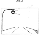
- FIG. 4 is a diagram illustrating an example of the first exposure image acquired in step S102.
- a first exposure image T111 illustrated in FIG. 4 includes an image region T112 corresponding to the electric sign T101 in FIG. 2 .
- image region T112 overexposure due to pixel saturation occurs in an image region T113 corresponding to the light emitting portion of the electric sign T101.
- step S103 the light source detection unit 103 detects the light source region from the first exposure image acquired in step S102.
- the image region T113 in the first exposure image T111 in FIG. 4 is detected as the light source region, and information of the center position, width, and height thereof is calculated.
- step S104 the size specifying unit 104 specifies the size of the electric sign that is the object to be recognized by the object recognition device 10, on the basis of the light source region detected in step S103.
- the size of the object is specified from the light source region. Note that the magnification at this time can be set in advance according to the type of the object as the recognition target.
- step S105 the exposure amount determination unit 101 calculates the second exposure amount C101.
- the exposure amount with which pixel saturation does not occur in the light emitting portion of the electric sign which is the object as the recognition target, at the time of imaging by the imaging device 20 is calculated as the second exposure amount C101.
- step S106 the image acquisition unit 102 acquires an image captured by the imaging device 20 with the second exposure amount C101 determined in step S105, from the imaging device 20 to set the image as a second exposure image.
- FIG. 5 is a diagram illustrating an example of the second exposure image acquired in step S106.
- a second exposure image T121 illustrated in FIG. 5 includes an image region T122 corresponding to the electric sign T101 in FIG. 2 .
- the image region T122 unlike the image region T113 in FIG. 4 , overexposure due to the pixel saturation does not occur in an image region T123 corresponding to the light emitting portion of the electric sign T101.
- step S107 the recognition candidate extraction unit 105 extracts a recognition candidate for performing the recognition processing, from the second exposure image acquired in step S106.
- a region to be extracted as the recognition candidate in the second exposure image is determined on the basis of the center position of the light source region detected in step S103 and the size (height, width) of the electric sign specified in step S104.
- FIG. 6 is a diagram illustrating an example of a recognition candidate extracted in step S107.
- the second exposure image T121 illustrated in FIG. 6 is the same as that illustrated in FIG. 5 .
- a recognition candidate T132 is set around the image region T122 corresponding to the electric sign T101 in the second exposure image T121, and is extracted.
- the center position of the recognition candidate T132 is set from the center position of the light source region detected in step S103.
- the height and width of the recognition candidate T132 are set from the height and width representing the size of the electric sign specified in step S104, respectively.
- step S108 the recognition processing unit 106 performs recognition processing on the recognition candidate extracted in step S107.
- the template matching processing is performed using a template image having the same size as the extracted recognition candidate, and a template image having the highest correlation is specified among the plurality of template images.
- the object recognition device 10 of the present embodiment performs the recognition processing by estimating the size of the object from the image captured using the exposure amount with which at least a part of the light emitting portion is pixel saturated.
- the size of the template image used for the recognition processing can be narrowed down according to the size of the object, so that the processing time can be reduced. As a result, it is possible to accurately recognize the object in a short processing time.
- FIG. 7 is a functional block diagram illustrating a configuration of an object recognition device according to the second embodiment of the present invention.
- an object recognition device 10A of the present embodiment is connected to the imaging device 20 and the vehicle control device 30, similar to the object recognition device 10 according to the first embodiment described with reference to FIG. 1 .
- the object recognition device 10A of the present embodiment includes an exposure amount determination unit 201, an image acquisition unit 202, a light source detection unit 203, a size specifying unit 204, a recognition candidate extraction unit 205, a recognition processing unit 206, and a size information storage unit 207.
- the object recognition device 10A is configured using a computer having, for example, an arithmetic device such as a CPU and a storage device such as a ROM, a RAM, and a flash memory, and is operated as each functional block described above by executing a control program stored in the storage device by the arithmetic device. Note that some or all of the functions of the object recognition device 10A may be configured using hardware such as an FPGA.
- the exposure amount determination unit 201 calculates two types of exposure amounts for controlling the brightness of the imaging device 20, that is, a first exposure amount F201 and a second exposure amount C201, and outputs these calculated exposure amounts to the imaging device 20.
- the image acquisition unit 202 acquires, as the first exposure image and the second exposure image, two types of images respectively captured by the imaging device 20 with the first exposure amount F201 and the second exposure amount C201 that are determined by the exposure amount determination unit 201.
- the light source detection unit 203 detects the light source region from the first exposure image, and outputs the detection result to the size specifying unit 204 and the recognition candidate extraction unit 205.
- the size specifying unit 204 specifies the size of the object to be recognized by the object recognition device 10A, from each piece of information of the center position, the width, and the height of the light source region indicated by the output of the light source detection unit 203, and outputs the size to the recognition candidate extraction unit 205.
- the light source detection unit 203 estimates the size of the object on the image by referring to the size information stored in the size information storage unit 207, and specifies the size. The details of the size information stored in the size information storage unit 207 will be described later.
- the recognition candidate extraction unit 205 extracts the recognition candidate from the second exposure image on the basis of the position of the light source region detected by the light source detection unit 203 and the size of the object specified by the size specifying unit 204. Similar to the recognition processing unit 106 in FIG. 1 , the recognition processing unit 206 performs recognition processing on the recognition candidate extracted from the second exposure image by the recognition candidate extraction unit 205, and recognizes the type of the object and the display content in the object.
- the size information storage unit 207 stores size information indicating the relationship between the light emitting portion of the object as the recognition target and the size of the object.
- This size information can be expressed, for example, for each of the width and height of the object, as a magnification of the size of the object relative to the light emitting portion.
- the size information is not limited to the width and height of the object.
- the magnification with respect to the radius can be stored as the size information in the size information storage unit 207.
- any information regarding the relationship between the light emitting portion and the size of the object can be stored as the size information in the size information storage unit 207.
- the size information stored in the size information storage unit 207 may be rewritable in a stage before shipment such as a production line or the like of a factory in a case where a destination of the object recognition device 10A is determined.
- a stage before shipment such as a production line or the like of a factory
- the size information regarding the light emitting portion and the size of an object such as an electric sign arranged in the country is stored in the size information storage unit 207.
- the size information corresponding to the destination is stored.
- FIG. 8 is a flowchart illustrating a flow of processing of the object recognition device 10A according to the second embodiment of the present invention.
- the object recognition device 10A of the present embodiment is mounted on a vehicle, and performs the processing illustrated in the flowchart of FIG. 8 at predetermined processing cycles by, for example, an arithmetic device such as a CPU.
- an arithmetic device such as a CPU.
- the object recognition device 10A sequentially performs first exposure amount calculation processing (S201), image acquisition processing (S202), light source detection processing (S203), object type determination processing (S204), object size calculation processing (S205), second exposure amount calculation processing (S206), image acquisition processing (S207), recognition candidate extraction processing (S208), and recognition processing (S209), and thereby recognizes the type and display contents of the electric sign as the recognition target.
- first exposure amount calculation processing S201
- image acquisition processing S202
- light source detection processing S203
- object type determination processing S204
- object size calculation processing S205
- second exposure amount calculation processing S206
- image acquisition processing S207
- recognition candidate extraction processing S208
- recognition processing S209
- steps S201 to S203 processing similar to the processing in steps S101 to S103 in FIG. 3 is performed by the exposure amount determination unit 201, the image acquisition unit 202, and the light source detection unit 203, respectively.
- step S204 the size specifying unit 104 determines which object type of size information is referred to in the size information stored in the size information storage unit 207 on the basis of the light source region detected in step S203.
- the object as the recognition target is the electric sign
- the result that the object type is the electric sign is obtained by the object type determination processing in step S204.
- step S205 the size specifying unit 104 calculates the size of the object to be recognized by the object recognition device 10A by referring to the size information stored in the size information storage unit 207 on the basis of the determination result in step S204.
- the size of the object is calculated with reference to the size information illustrated in the table of FIG. 9 .
- FIG. 9 is a diagram illustrating an example of the size information stored in the size information storage unit 207.
- the magnifications of the height and the width with respect to the object including the light emitting portion are described in a table format for each type of object.
- the second row describes size information on the road sign
- the third row describes size information on the vehicle.
- step S204 in the object type determination processing (S204), the determination result that the type of the object as the recognition target is the electric sign is obtained as described above. Therefore, in step S205, by referring to the portion of the road sign in the size information of FIG. 9 , it can be seen that both the magnifications of the electric sign with respect to the width and the height of the light emitting portion detected as the light source region are 1.2 times. Therefore, the size of the electric sign in the captured image can be specified by multiplying the width and height of the light source region acquired in the light source detection processing (S203) by the magnifications illustrated in FIG. 9 , respectively.
- steps S206 to S209 processing similar to the processing in steps S105 to S108 in FIG. 3 is performed by the exposure amount determination unit 201, the image acquisition unit 202, the recognition candidate extraction unit 205, and the recognition processing unit 206, respectively.
- the size of the object as the recognition target can be estimated more accurately by using the relationship between the light emitting portion and the size created in advance. As a result, it is possible to select the region where the recognition processing is to be performed, and it is possible to improve the recognition accuracy more accurately.
- the object recognition device 10A further includes the size information storage unit 207 in which size information indicating the relationship between the light emitting portion of the object and the size of the object is stored for each type of the object.
- the size specifying unit 24 specifies the size of the object by referring to the size information stored in the size information storage unit 207 on the basis of the size of the light source region detected by the light source detection unit 203.
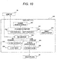
- FIG. 10 is a functional block diagram illustrating a configuration of an object recognition device according to the third embodiment of the present invention.
- an object recognition device 10B of the present embodiment is connected to the imaging device 20 and the vehicle control device 30, similar to the object recognition device 10 according to the first embodiment described with reference to FIG. 1 .
- the object recognition device 10B of the present embodiment includes an exposure amount determination unit 301, an image acquisition unit 302, a light source detection unit 303, a size specifying unit 304, a recognition candidate extraction unit 305, a recognition processing unit 306, an environment information acquisition unit 307, and a luminance information storage unit 308.
- the object recognition device 10B is configured using a computer having, for example, an arithmetic device such as a CPU and a storage device such as a ROM, a RAM, and a flash memory, and is operated as each functional block described above by executing a control program stored in the storage device by the arithmetic device. Note that some or all of the functions of the object recognition device 10B may be configured using hardware such as an FPGA.
- the environment information acquisition unit 307 acquires environment information around the object recognition device 10B, and outputs the environment information to the exposure amount determination unit 301.
- the environment information acquired by the environment information acquisition unit 307 is, for example, information on a time zone or a location (country, region, or the like) in which the object recognition device 10B is operating, and corresponds to information indicating a traveling environment of the host vehicle on which the object recognition device 10B is mounted.
- the environment information acquisition unit 307 is connected to a navigation system (not illustrated), and can acquire environment information by acquiring information on a location and a time zone from the navigation system.
- the navigation system receives, for example, a global positioning system (GPS) signal, and specifies the location corresponding to its own current position by comparing a position indicated by the received GPS signal with a map. In addition, it is possible to specify the time zone by detecting the current time from the received GPS signal.
- GPS global positioning system
- the environment information acquisition unit 307 can acquire the environment information using any other means.
- the luminance information storage unit 308 stores luminance information regarding the brightness of the light emitting portion of the object as the recognition target.
- this luminance information for example, the brightness of the light emitting portion is set for each location or time zone.
- the luminance information can be represented by various physical quantities such as luminance [cd/m 2 ] and illuminance [lx] .
- the exposure amount determination unit 301 determines a first exposure amount F301 and a second exposure amount C301 by referring to the luminance information stored in the luminance information storage unit 308 on the basis of the environment information acquired by the environment information acquisition unit 307. Specifically, the exposure amount determination unit 301 acquires the brightness of the light emitting portion of the object as the recognition target corresponding to the environment information acquired by the environment information acquisition unit 307, from the luminance information stored in the luminance information storage unit 308. Then, the first exposure amount F301 and the second exposure amount C301 are set on the basis of the acquired brightness of the light emitting portion.
- the first exposure amount F301 is set such that a pixel value of the light emitting portion in the captured image is a predetermined reference value or more
- the second exposure amount C301 is set such that a pixel value of the light emitting portion in the captured image is a predetermined reference value or less.
- the reference values in these settings may be the same value or different values.
- the image acquisition unit 302 acquires, as the first exposure image and the second exposure image, two types of images respectively captured by the imaging device 20 with the first exposure amount F301 and the second exposure amount C301 that are determined by the exposure amount determination unit 301.
- the light source detection unit 303 detects the light source region from the first exposure image, and outputs the detection result to the size specifying unit 304 and the recognition candidate extraction unit 305.
- the size specifying unit 304 specifies the size of the object to be recognized by the object recognition device 10B, from each piece of information of the center position, the width, and the height of the light source region indicated by the output of the light source detection unit 303, and outputs the size to the recognition candidate extraction unit 305.
- the recognition candidate extraction unit 305 extracts the recognition candidate from the second exposure image on the basis of the position of the light source region detected by the light source detection unit 303 and the size of the object specified by the size specifying unit 304. Similar to the recognition processing unit 106 in FIG. 1 , the recognition processing unit 306 performs recognition processing on the recognition candidate extracted from the second exposure image by the recognition candidate extraction unit 305, and recognizes the type of the object and the display content in the object.
- FIG. 11 is a flowchart illustrating a flow of processing of the object recognition device 10B according to the third embodiment of the present invention.
- the object recognition device 10B of the present embodiment is mounted on a vehicle, and performs the processing illustrated in the flowchart of FIG. 11 at predetermined processing cycles by, for example, an arithmetic device such as a CPU.
- an arithmetic device such as a CPU.
- the object recognition device 10B sequentially performs environment information acquisition processing (S300), first exposure amount setting processing (S301), image acquisition processing (S302), light source detection processing (S303), size specification processing (S304), second exposure amount setting processing (S305), image acquisition processing (S306), recognition candidate extraction processing (S307), and recognition processing (S308), and thereby recognizes the type and display contents of the electric sign as the recognition target.
- environment information acquisition processing S300
- first exposure amount setting processing S301
- image acquisition processing S302
- S303 light source detection processing
- S304 size specification processing
- S305 second exposure amount setting processing
- image acquisition processing S306
- recognition candidate extraction processing S307
- recognition processing recognition processing
- step S300 the environment information acquisition unit 307 acquires the environment information around the object recognition device 10B.
- information on the current time and the traveling country of the host vehicle is acquired as the environment information around the object recognition device 10B.
- the exposure amount determination unit 301 sets the first exposure amount F301 by referring to the luminance information stored in the luminance information storage unit 308 on the basis of the environment information acquired in step S300.
- the luminance information illustrated in the table of FIG. 12 the brightness of the light emitting portion of the electric sign which is the object to be recognized by the object recognition device 10B is specified, and the first exposure amount F301 corresponding to the brightness is set.
- FIG. 12 is a diagram illustrating an example of the luminance information stored in the luminance information storage unit 308.
- the luminance information in FIG. 12 the brightness of the light emitting portion of the electric sign is described in a table format for each time zone and traveling country. Specifically, each row in the table corresponds to a time zone, each column corresponds to a traveling country (Japan, Germany), and information on the brightness of the light emitting portion of the electric sign is stored for each combination thereof.
- the brightness of the light emitting portion of the electric sign in the time zone from 6 o'clock to 9 o'clock is 50 [cd/m 2 ]
- the brightness of the light emitting portion of the electric sign in the time zone from 9 o'clock to 15 o'clock is 100 [cd/m 2 ]
- the brightness of the light emitting portion of the electric sign in the time zone from 15 o'clock to 19 o'clock is 70 [cd/m 2 ]
- the brightness of the light emitting portion of the electric sign in the time zone from 19 o'clock to 6 o'clock is 60 [cd/m 2 ].
- the exposure amount with which pixel saturation occurs at the time of imaging can be set as the first exposure amount F301 on the basis of the brightness.
- steps S302 to S304 processing similar to the processing in steps S102 to S104 in FIG. 3 is performed by the image acquisition unit 302, the light source detection unit 303, and the size specifying unit 304, respectively.
- step S305 the exposure amount determination unit 301 sets the second exposure amount C301 by referring to the luminance information stored in the luminance information storage unit 308 on the basis of the environment information acquired in step S300.
- the luminance information illustrated in the table of FIG. 12 the brightness of the light emitting portion of the electric sign which is the object to be recognized by the object recognition device 10B is specified, and the second exposure amount C301 corresponding to the brightness is set.
- the brightness of the light emitting portion of the electric sign is 60 [cd/m 2 ] at 20 o'clock, which is the current time, in Japan, which is the traveling country of the host vehicle. Therefore, the exposure amount with which pixel saturation does not occur at the time of imaging can be set as the second exposure amount C301 on the basis of the brightness.
- steps S306 to S308 processing similar to the processing in steps S106 to S108 in FIG. 3 is performed by the image acquisition unit 302, the recognition candidate extraction unit 305, and the recognition processing unit 306, respectively.
- the object recognition device 10B of the present embodiment adaptively changes the exposure amount at the time of imaging by acquiring the luminance information regarding the brightness of the light emitting portion corresponding to the current environment around the object recognition device 10B.
- the exposure amount at the time of imaging for an object of which the brightness is changed according to a location or a time zone, such as the light emitting portion of the electric sign, and it is possible to improve the detection accuracy and the recognition accuracy of the object.
- the object recognition device 10B further includes the environment information acquisition unit 307 that acquires the environment information around the object recognition device 10B, and the luminance information storage unit 308 that stores the luminance information of the light emitting portion of the object for each environment.
- the exposure amount determination unit 301 determines the first exposure amount F301 and the second exposure amount C301 by referring to the luminance information stored in the luminance information storage unit 308 on the basis of the environment information acquired by the environment information acquisition unit 307. With this configuration, the exposure amount at the time of imaging can be set more appropriately, and thus it is possible to improve the detection accuracy and the recognition accuracy of the object.
- the environment information acquisition unit 307 can acquire information including at least one of a time zone and a location in which the object recognition device 10B is operating, as the environment information. With this configuration, information required for setting the exposure amount at the time of imaging can be reliably and easily acquired as the environment information.
- FIG. 13 is a functional block diagram illustrating a configuration of an object recognition device according to the fourth embodiment of the present invention.
- an object recognition device 10C of the present embodiment is connected to the imaging device 20 and the vehicle control device 30, similar to the object recognition device 10 according to the first embodiment described with reference to FIG. 1 .
- the object recognition device 10C of the present embodiment includes an exposure amount determination unit 401, an image acquisition unit 402, a light source detection unit 403, a size specifying unit 404, a recognition candidate extraction unit 405, a recognition processing unit 406, a three-dimensional position calculation unit 407, and a behavior information acquisition unit 408.
- the object recognition device 10C is configured using a computer having, for example, an arithmetic device such as a CPU and a storage device such as a ROM, a RAM, and a flash memory, and is operated as each functional block described above by executing a control program stored in the storage device by the arithmetic device. Note that some or all of the functions of the object recognition device 10C may be configured using hardware such as an FPGA.
- the exposure amount determination unit 401 calculates two types of exposure amounts for controlling the brightness of the imaging device 20, that is, a first exposure amount F401 and a second exposure amount C401, and outputs these calculated exposure amounts to the imaging device 20.
- the image acquisition unit 402 acquires, as the first exposure image and the second exposure image, two types of images respectively captured by the imaging device 20 with the first exposure amount F401 and the second exposure amount C401 that are determined by the exposure amount determination unit 401.
- the light source detection unit 403 detects the light source region from the first exposure image, and outputs the detection result to the size specifying unit 404, the recognition candidate extraction unit 405, and the three-dimensional position calculation unit 407.
- the size specifying unit 404 specifies the size of the object to be recognized by the object recognition device 10C, from each piece of information of the center position, the width, and the height of the light source region indicated by the output of the light source detection unit 403, and outputs the size to the recognition candidate extraction unit 405 and the three-dimensional position calculation unit 407.
- the three-dimensional position calculation unit 407 calculates the three-dimensional position of the object as the recognition target, from the output of the light source detection unit 403 and the size specifying unit 404, and outputs the calculated three-dimensional position to the recognition candidate extraction unit 405.
- the three-dimensional position calculation unit 407 has, for example, actual size information of an object in the real world and information regarding optical parameters of the imaging device 20.
- the optical parameter is a parameter regarding a lens or an imaging element included in the imaging device 20, such as a focal length or an actual size of a pixel.
- the three-dimensional position calculation unit 407 estimates a distance in a depth direction from the object recognition device 10C to the object using the size information of the object on the captured image output by the size specifying unit 404 and the actual size information and optical parameters of the object held by the three-dimensional position calculation unit 407. Then, the position of the object with respect to the object recognition device 10C is estimated for each of the horizontal direction and the vertical direction orthogonal to the depth direction, using the estimated distance in the depth direction, the center position of the light source region detected by the light source detection unit 403, and the optical parameters held by the three-dimensional position calculation unit 407.
- the three-dimensional position calculation unit 407 calculates the three-dimensional position of the object by estimating the position of the object based on the object recognition device 10C for each of the depth direction, the horizontal direction, and the vertical direction in this manner.
- the three-dimensional position of the object calculated by the three-dimensional position calculation unit 407 is output to the recognition candidate extraction unit 405.
- the behavior information acquisition unit 408 acquires behavior information regarding the behavior of a moving body on which the object recognition device 10C is mounted. Specifically, for example, in a case where the moving body is a vehicle, information on a traveling speed, a steering angle, and a yaw rate, and the like of the vehicle can be acquired as the behavior information of the vehicle via a network such as a controller area network (CAN) provided in the vehicle. Note that the behavior information acquisition unit 408 may acquire other information as the behavior information. In addition, the behavior information may be acquired via a network other than the CAN, or the behavior information may be acquired by another method. As long as the information relates to the behavior of the moving body on which the object recognition device 10C is mounted, the behavior information acquisition unit 408 can use arbitrary information acquired by an arbitrary method as the behavior information.
- a network such as a controller area network (CAN) provided in the vehicle.
- the behavior information acquisition unit 408 may acquire other information as the behavior information.
- the behavior information may be acquired via a network other than the
- the recognition candidate extraction unit 405 extracts a recognition candidate from the second exposure image on the basis of the output of each of the light source detection unit 403, the size specifying unit 404, the three-dimensional position calculation unit 407, and the behavior information acquisition unit 408. Specifically, first, the movement amount of the moving body in a period from when the imaging device 20 captures the first exposure image to when the imaging device 20 captures the second exposure image is calculated on the basis of the behavior information acquired by the behavior information acquisition unit 408. Next, the three-dimensional position of the object at the time of capturing the second exposure image is estimated by applying the calculated movement amount to the three-dimensional position of the object at the time of capturing the first exposure image, which is calculated by the three-dimensional position calculation unit 407.
- a recognition candidate is extracted by extracting, from the second exposure image, a region corresponding to the size of the object specified by the size specifying unit 204 at the estimated three-dimensional position.
- the recognition candidate extraction unit 405 can extract a recognition candidate corresponding to the three-dimensional position of the object, from the second exposure image in this manner, for example.
- the recognition processing unit 406 performs recognition processing, on the recognition candidate extracted from the second exposure image by the recognition candidate extraction unit 405, and recognizes the type of the object and the display content in the object.
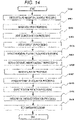
- FIG. 14 is a flowchart illustrating a flow of processing of the object recognition device 10C according to the fourth embodiment of the present invention.
- the object recognition device 10C of the present embodiment is mounted on a vehicle, and performs the processing illustrated in the flowchart of FIG. 14 at predetermined processing cycles by, for example, an arithmetic device such as a CPU.
- an arithmetic device such as a CPU.
- the object recognition device 10C sequentially performs first exposure amount calculation processing (S400), image acquisition processing (S401), light source detection processing (S402), size specification processing (S403), three-dimensional position calculation processing (S404), second exposure amount calculation processing (S405), image acquisition processing (S406), vehicle information acquisition processing (S407), object position prediction processing (S408), recognition candidate extraction processing (S409), and recognition processing (S410), and thereby recognizes the type and display contents of the electric sign as the recognition target.
- first exposure amount calculation processing S400
- image acquisition processing S401
- light source detection processing S402
- size specification processing S403
- three-dimensional position calculation processing S404
- second exposure amount calculation processing S405
- image acquisition processing S406
- vehicle information acquisition processing S407
- object position prediction processing S408
- recognition candidate extraction processing S409
- recognition processing recognition processing
- steps S400 to S403 processing similar to the processing in steps S101 to S104 in FIG. 3 is performed by the exposure amount determination unit 401, the image acquisition unit 402, the light source detection unit 403, and the size specifying unit 404, respectively.
- step S404 the three-dimensional position calculation unit 407 calculates the three-dimensional position of the object on the basis of the position of the light source region detected in step S402 and the size of the object as the recognition target specified in step S403.
- the three-dimensional position of the object is calculated according to the processing flow illustrated in FIG. 15 described below.
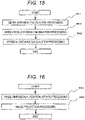
- FIG. 15 is a flowchart of the three-dimensional position calculation processing.
- the three-dimensional position calculation unit 407 sequentially performs depth distance calculation processing (S411), horizontal distance calculation processing (S412), and vertical distance calculation processing (S413), and thereby acquires three-dimensional position information of the object.
- a depth distance Z is obtained using the following Equation (1).
- Z f / w * R / O
- Equation (1) f represents the focal length of the imaging device 20
- w represents the size of the imaging element of the imaging device 20
- R represents the actual size of the object as the recognition target
- O represents the size of the object on the captured image specified in step S403. Note that, as long as R and O are in the same direction, either the width direction or the height direction may be used. That is, the actual dimension width of the object as the recognition target and the width on the captured image may be used as R and O, respectively, or the actual dimension height of the object as the recognition target and the height on the captured image may be used as R and O, respectively.
- a horizontal distance X is obtained using the following Equation (2).
- X wx / f * Z * cx ⁇ ox
- Equation (2) wx represents the horizontal width of the imaging element included in the imaging device 20
- f represents the focal length of the imaging device 20
- Z represents the depth distance of the object obtained by Equation (1) in the depth distance calculation processing in step S411
- cx represents the position of the light source region in the horizontal direction on the captured image detected in step S402
- ox represents the central position of the captured image in the horizontal direction.
- a vertical distance Y is obtained using the following Equation (3).
- Y wy / f * Z * cy ⁇ oy
- Equation (3) wy represents the vertical width of the imaging element included in the imaging device 20
- f represents the focal length of the imaging device 20
- Z represents the depth distance of the object obtained by Equation (1) in the depth distance calculation processing in step S411
- cy represents the position of the light source region in the vertical direction on the captured image detected in step S402
- oy represents the central position of the captured image in the vertical direction.
- step S404 the three-dimensional position of the object as the recognition target is acquired by the above calculation.
- steps S405 and S406 processing similar to the processing in steps S105 and S106 in FIG. 3 is performed by the exposure amount determination unit 401 and the image acquisition unit 402, respectively.
- the behavior information acquisition unit 408 acquires behavior information of the moving body.
- behavior information for example, information on a traveling speed, a steering angle, a yaw rate, and the like of a vehicle that is a moving body is acquired as the behavior, information.
- the recognition candidate extraction unit 405 predicts the position of the object in the second exposure image on the basis of the three-dimensional position of the object calculated in step S404 and the behavior information acquired in step S407.
- the position of the object is predicted according to the processing flow illustrated in FIG. 16 described below.
- FIG. 16 is a flowchart of the object position prediction processing.
- the recognition candidate extraction unit 405 sequentially performs three-dimensional position update processing (S421) and image projection processing (S422), and thereby predicts the position of the object.
- the three-dimensional position of the object calculated in step S404 is updated to the three-dimensional position at the time of capturing the second exposure image, by using the behavior information acquired in step S407. That is, since the three-dimensional position of the object calculated in step S407 is the position of the object at the time of capturing the first exposure image, the three-dimensional position of the object is updated on the basis of the movement amount of the moving body in the period from when the imaging device 20 captures the first exposure image to when the imaging device 20 captures the second exposure image.
- the movement amount of the vehicle as the moving body is calculated for each of the depth direction, the horizontal direction, and the vertical direction using the information on the speed, the steering angle, the yaw rate, and the like included in the behavior information. Thereafter, the three-dimensional position is updated to the three-dimensional position at the time of capturing the second exposure image by subtracting the movement amount of the vehicle from the three-dimensional position calculated in step S407.
- the position of the object in the second exposure image is predicted by projecting the three-dimensional position of the object updated in step S421 on the second exposure image.
- step S408 the position of the object in the second exposure image is predicted by the above processing.
- the recognition candidate extraction unit 405 extracts a recognition candidate for performing the recognition processing, from the second exposure image on the basis of the position of the object predicted in step S408.
- a region to be extracted as the recognition candidate in the second exposure image is determined by applying the size (height, width) of the object specified in step S403 to the position of the object on the second exposure image obtained in step S422.
- the width and height of the region to be extracted as the recognition candidate may be determined in consideration of the movement amount of the vehicle calculated in step S421 and the actual size of the object.
- step S410 the recognition processing unit 406 performs recognition processing similar to that in step S107 in FIG. 3 on the recognition candidate extracted in step S409.
- the region to be extracted as the recognition candidate from the second exposure image is determined in consideration of the movement amount of the moving body in the period from when the imaging device 20 captures the first exposure image to when the imaging device 20 captures the second exposure image.
- the object recognition device 10C further includes the three-dimensional position calculation unit 407 that calculates the three-dimensional position of the object, and the behavior information acquisition unit 408 that acquires the behavior information regarding the behavior of the moving body on which the object recognition device 10C is mounted.
- the recognition candidate extraction unit 405 extracts the recognition candidate on the basis of the position of the light source region, the size of the object, the three-dimensional position of the object, and the behavior information. With this configuration, the recognition candidate can be determined in consideration of the movement amount of the moving body, and thus it is possible to improve the recognition performance for the object.
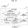
- FIG. 17 is a functional block diagram illustrating a configuration of an object recognition device according to the fifth embodiment of the present invention.
- an object recognition device 10D of the present embodiment is connected to the imaging device 20 and the vehicle control device 30, similar to the object recognition device 10 according to the first embodiment described with reference to FIG. 1 .
- the object recognition device 10D of the present embodiment includes an exposure amount determination unit 501, an image acquisition unit 502, a light source detection unit 503, a size specifying unit 504, a recognition candidate extraction unit 505, a recognition processing unit 506, an environment information acquisition unit 507, a luminance information storage unit 508, and a recognition candidate correction unit 509.
- the object recognition device 10D is configured using a computer having, for example, an arithmetic device such as a CPU and a storage device such as a ROM, a RAM, and a flash memory, and is operated as each functional block described above by executing a control program stored in the storage device by the arithmetic device. Note that some or all -of the functions of the object recognition device 10D may be configured using hardware such as an FPGA.
- the environment information acquisition unit 507 acquires environment information around the object recognition device 10D, and outputs the environment information to the exposure amount determination unit 501. Similar to the luminance information storage unit 308 in FIG. 10 described in the third embodiment, the luminance information storage unit 508 stores luminance information regarding the brightness of the light emitting portion of the object as the recognition target.
- the exposure amount determination unit 501 determines a first exposure amount F501 and a second exposure amount C501 by referring to the luminance information stored in the luminance information storage unit 508 on the basis of the environment information acquired by the environment information acquisition unit 507.
- the image acquisition unit 502 acquires, as the first exposure image and the second exposure image, two types of images respectively captured by the imaging device 20 with the first exposure amount F501 and the second exposure amount C501 that are determined by the exposure amount determination unit 501.
- the light source detection unit 503 detects the light source region from the first exposure image, and outputs the detection result to the size specifying unit 504 and the recognition candidate extraction unit 505.
- the size specifying unit 504 specifies the size of the object to be recognized by the object recognition device 10D, from each piece of information of the center position, the width, and the height of the light source region indicated by the output of the light source detection unit 503, and outputs the size to the recognition candidate extraction unit 505.
- the recognition candidate extraction unit 505 extracts the recognition candidate from the second exposure image on the basis of the position of the light source region detected by the light source detection unit 503 and the size of the object specified by the size specifying unit 504.
- the recognition candidate correction unit 509 corrects at least one of the position, size, and shape of the recognition candidate extracted by the recognition candidate extraction unit 505, on the second exposure image, extracts the recognition candidate after the correction, and outputs the recognition candidate after the correction to the recognition processing unit 506.
- the recognition candidate correction unit 509 can correct the position, size, and shape of the recognition candidate by once enlarging the region output as the recognition candidate by the recognition candidate extraction unit 505 in the second exposure image and reducing the region on the basis of the luminance information of the enlarged region.
- the brightness of the light emitting portion of the object in the second exposure image is estimated on the basis of the luminance information stored in the luminance information storage unit 508, and each pixel having a luminance value similar to the estimated brightness of the light emitting portion, that is, each pixel of which a luminance difference with the light emitting portion is less than a predetermined threshold is extracted from the enlarged region of the recognition candidate. Then, the region of the recognition candidate is reduced such that, for example, the pixel density in the region is equal to or greater than a predetermined value on the basis of the distribution of the extracted pixels.
- the correction of the recognition candidate can be performed by setting the position, size, and shape of the recognition candidate of which the region has been reduced on the second exposure image as the position, size, and shape of the recognition candidate after the correction.
- the correction of the recognition candidate may be performed by binarizing the luminance information of the enlarged region.
- the luminance information can be binarized by setting the luminance value of the pixel of which the difference with the brightness of the light emitting portion is less than the predetermined threshold as 255 and setting the luminance value of the pixel of which the difference with the brightness of the light emitting portion is equal to or greater than the threshold as 0.
- the projection histograms are calculated in the vertical direction and the horizontal direction, the peak of each histogram is detected, and thereby the position, size, and shape of the recognition candidate after the correction can be determined.
- a model capable of estimating a regression coefficient with respect to the position of the object may be learned for each brightness of the light emitting portion, and the position, size, and shape of the recognition candidate after the correction may be determined by switching the model to be used according to the brightness of the light emitting portion of the object in the second exposure image estimated from the luminance information.
- the recognition processing unit 506 performs recognition processing similar to that of the recognition processing unit 106 in FIG. 1 on the recognition candidate corrected on the second exposure image by the recognition candidate correction unit 509, and thereby recognizes the type of the object and the display content of the object.
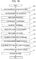
- FIG. 18 is a flowchart illustrating a flow of processing of the object recognition device 10D according to the fifth embodiment of the present invention.
- the object recognition device 10D of the present embodiment is mounted on a vehicle, and performs the processing illustrated in the flowchart of FIG. 18 at predetermined processing cycles by, for example, an arithmetic device such as a CPU.
- an arithmetic device such as a CPU.
- the object recognition device 10D sequentially performs environment information acquisition processing (S500), first exposure amount setting processing (S501), image acquisition processing (S502), light source detection processing (S503), size specification processing (S504), second exposure amount setting processing (S505), image acquisition processing (S506), recognition candidate extraction processing (S507), recognition candidate enlargement processing (S508), light emitting portion brightness estimation processing (S509), recognition candidate re-extraction processing (S510), and recognition processing (S511), and thereby recognizes the type and display contents of the electric sign as the recognition target.
- S500 environment information acquisition processing
- S501 first exposure amount setting processing
- image acquisition processing S502
- light source detection processing S503
- size specification processing S504
- second exposure amount setting processing S505
- image acquisition processing S506
- recognition candidate extraction processing S507
- recognition candidate enlargement processing S508
- S509 recognition candidate enlargement processing
- S510 recognition candidate re-extraction processing
- S511 recognition processing
- step S500 the environment information acquisition unit 507 acquires the environment information around the object recognition device 10D, similar to step S300 in FIG. 11 .
- step S501 the exposure amount determination unit 501 sets the first exposure amount F501 by referring to the luminance information stored in the luminance information storage unit 508 on the basis of the environment information acquired in step S500, similar to step S301 in FIG. 11 .
- steps S502 to S504 processing similar to the processing in steps S102 to S104 in FIG. 3 is performed by the image acquisition unit 502, the light source detection unit 503, and the size specifying unit 504, respectively.
- step S505 the exposure amount determination unit 501 sets the second exposure amount C501 by referring to the luminance information stored in the luminance information storage unit 508 on the basis of the environment information acquired in step S500, similar to step S305 in FIG. 11 .
- steps S506 and S507 processing similar to the processing in steps S106 and S107 in FIG. 3 is performed by the image acquisition unit 502 and the recognition candidate extraction unit 505, respectively.
- the recognition candidate correction unit 509 enlarges the recognition candidate extracted in step S507 on the second exposure image.
- the recognition candidate is enlarged by multiplying the region of the second exposure image extracted as the recognition candidate by predetermined magnifications in the width direction and the height direction.
- the magnifications to be multiplied in the width direction and the height direction may be the same value or different values.
- the recognition candidate correction unit 509 estimates the brightness of the light emitting portion of the object in the second exposure image by referring to the luminance information stored in the luminance information storage unit 508.
- the brightness of the light emitting portion in the second exposure image can be estimated by calculating the luminance value of the second exposure image corresponding to the brightness of the light emitting portion indicated by the luminance information on the basis of the second exposure amount C501 set in step S505.
- step S510 the recognition candidate correction unit 509 resets the recognition candidate by reducing the recognition candidate enlarged in step S508, on the basis of the brightness of the light emitting portion in the second exposure image estimated in step S509. Then, the reset recognition candidate is re-extracted as a recognition candidate after the correction.
- the recognition candidate is re-extracted according to the processing flow illustrated in FIG. 19 described below.
- FIG. 19 is a flowchart of the recognition candidate re-extraction processing.
- the recognition candidate correction unit 509 sequentially performs image binarization processing (S520), projection histogram calculation (S521), width estimation processing (S522), and height estimation processing (S523), and thereby re-extracts the recognition candidate.
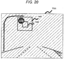
- a second exposure image T501 illustrated in FIG. 20 is acquired in step S506, and from the second exposure image T501, an image region T502 is extracted as the recognition candidate in step S507, and an image region T503 is obtained as a recognition candidate after enlargement in step S508.
- the luminance value of each pixel in the image region T503 in FIG. 20 is binarized on the basis of the brightness of the light emitting portion estimated in step S509. Specifically, for example, as described above, the luminance value of the pixel of which the difference with the brightness of the light emitting portion is less than the predetermined threshold is set as 255, and the luminance value of the pixel of which the difference with the brightness of the light emitting portion is equal to or greater than the threshold is set as 0.
- FIG. 21 is a diagram illustrating an example of a recognition candidate after the binarization processing and a projection histogram.
- a binarized image T511 illustrates a result of performing the binarization processing on each pixel of the image region T503 that is the recognition candidate after enlargement illustrated in FIG. 20 .
- each pixel of which the luminance value is set as 255 by the binarization processing is indicated in white
- each pixel of which the luminance value is set as 0 is indicated in black.
- Each pixel indicated in white corresponds to the light emitting portion of the electric sign which is the object as the recognition target
- each pixel indicated in black corresponds to the other portion.
- the projection histogram for the column direction and the row direction of the binarized image T511 obtained by the image binarization processing in step S520 is calculated.
- the projection histogram is calculated by adding the number of pixels having a luminance value of 255 in the binarized image T511 in the column direction and the row direction.
- a histogram T512 is an example of the projection histogram calculated for the binarized image T511 in the column direction
- a histogram T513 is an example of the projection histogram calculated for the binarized image T511 in the row direction.
- the width of the recognition candidate after the correction is estimated on the basis of the histogram obtained by the projection histogram calculation in step S521.
- the width of the recognition candidate after the correction is estimated using the histogram T512 calculated for the binarized image T511 in the column direction, that is, the histogram T512 indicating the peak position in the horizontal direction.
- a rising point and a falling point located at both ends of the peak portion having a value equal to or larger than a threshold T514 in the histogram T512 are acquired as a minimum point P1 and a maximum point P2, respectively.
- the number of columns between the acquired points P1 and P2 is estimated as the width of the recognition candidate after correction.
- the height of the recognition candidate after the correction is estimated on the basis of the histogram obtained by the projection histogram calculation in step S521.
- the height of the recognition candidate after the correction is estimated using the histogram T513 calculated for the binarized image T511 in the row direction, that is, the histogram T513 indicating the peak position in the vertical direction.
- a rising point and a falling point located at both ends of the peak portion having a value equal to or larger than a threshold T515 in the histogram T513 are acquired as a minimum point P3 and a maximum point P4, respectively.
- the number of rows between the acquired points P3 and P4 is estimated as the height of the recognition candidate after correction.
- the recognition candidate re-extraction processing in step S510 the width and height of the recognition candidate after correction are estimated by the above processing. Then, the recognition candidate is re-extracted by re-setting the recognition candidate on the second exposure image with the estimated width and height.
- step S511 the recognition processing unit 506 performs recognition processing similar to that in step S107 in FIG. 3 on the recognition candidate re-extracted in step S510.
- the object recognition device 10D of the present embodiment corrects the recognition candidate temporarily extracted from the second exposure image by performing the image processing, in which the brightness of the light emitting portion is taken into consideration, on the second exposure image. As a result, even in a case where it is difficult for the recognition candidate extraction unit 505 to extract an appropriate recognition candidate from the second exposure image, it is possible to maintain a high recognition accuracy.
- the object recognition device 10D further includes the recognition candidate correction unit 509 that corrects at least one of the position, size, and shape of the recognition candidate extracted by the recognition candidate extraction unit 505.
- the recognition processing unit 506 performs the recognition processing on the recognition candidate corrected by the recognition candidate correction unit 509.
- the recognition candidate correction unit 509 corrects the recognition candidate by enlarging the recognition candidate extracted by the recognition candidate extraction unit 505 and reducing the recognition candidate on the basis of the information on the luminance value of the enlarged recognition candidate. Specifically, the recognition candidate correction unit 509 estimates the brightness of the light emitting portion of the object in the second exposure image, and reduces the recognition candidate on the basis of the distribution of pixels having a luminance value similar to the brightness of the light emitting portion in the enlarged recognition candidate. With this configuration, it is possible to appropriately correct the recognition candidate in consideration of the brightness of the light emitting portion of the object in the second exposure image.
- the present invention can be applied as long as an object having a high-luminance light emitting portion, such as a preceding vehicle having a light emitting portion such as a brake lamp, a following vehicle having a light emitting portion such as a headlight, a traffic light, a signboard indicating a destination, and various electric bulletin boards is set as the recognition target.
- a high-luminance light emitting portion such as a preceding vehicle having a light emitting portion such as a brake lamp, a following vehicle having a light emitting portion such as a headlight, a traffic light, a signboard indicating a destination, and various electric bulletin boards is set as the recognition target.
Landscapes
- Engineering & Computer Science (AREA)
- Multimedia (AREA)
- Physics & Mathematics (AREA)
- General Physics & Mathematics (AREA)
- Theoretical Computer Science (AREA)
- Signal Processing (AREA)
- Software Systems (AREA)
- Data Mining & Analysis (AREA)
- Computer Vision & Pattern Recognition (AREA)
- Evolutionary Computation (AREA)
- Medical Informatics (AREA)
- Artificial Intelligence (AREA)
- Computing Systems (AREA)
- General Engineering & Computer Science (AREA)
- Mathematical Physics (AREA)
- Image Analysis (AREA)
- Traffic Control Systems (AREA)
Applications Claiming Priority (2)
| Application Number | Priority Date | Filing Date | Title |
|---|---|---|---|
| JP2019097048A JP7289723B2 (ja) | 2019-05-23 | 2019-05-23 | 物体認識装置 |
| PCT/JP2020/019399 WO2020235462A1 (fr) | 2019-05-23 | 2020-05-15 | Dispositif de reconnaissance d'objet |
Publications (2)
| Publication Number | Publication Date |
|---|---|
| EP3975151A1 true EP3975151A1 (fr) | 2022-03-30 |
| EP3975151A4 EP3975151A4 (fr) | 2023-01-25 |
Family
ID=73454030
Family Applications (1)
| Application Number | Title | Priority Date | Filing Date |
|---|---|---|---|
| EP20808827.8A Pending EP3975151A4 (fr) | 2019-05-23 | 2020-05-15 | Dispositif de reconnaissance d'objet |
Country Status (4)
| Country | Link |
|---|---|
| EP (1) | EP3975151A4 (fr) |
| JP (1) | JP7289723B2 (fr) |
| CN (1) | CN113826107A (fr) |
| WO (1) | WO2020235462A1 (fr) |
Families Citing this family (5)
| Publication number | Priority date | Publication date | Assignee | Title |
|---|---|---|---|---|
| CN112511749A (zh) * | 2020-11-30 | 2021-03-16 | 上海摩象网络科技有限公司 | 目标对象的自动曝光量控制方法、装置及电子设备 |
| JP2022187078A (ja) * | 2021-06-07 | 2022-12-19 | 株式会社Jvcケンウッド | 制御システム、制御方法およびプログラム |
| CN113179375A (zh) * | 2021-06-09 | 2021-07-27 | 北京澎思科技有限公司 | 曝光处理方法、装置、电子设备、存储介质及程序产品 |
| JP7739205B2 (ja) * | 2022-03-07 | 2025-09-16 | Astemo株式会社 | 車載カメラシステム、および、車載カメラの露光条件決定方法 |
| CN115546837B (zh) * | 2022-10-16 | 2023-06-23 | 三峡大学 | 变电站进出综合管理系统 |
Family Cites Families (20)
| Publication number | Priority date | Publication date | Assignee | Title |
|---|---|---|---|---|
| JP4253275B2 (ja) * | 2003-08-11 | 2009-04-08 | 株式会社日立製作所 | 車両制御システム |
| JP4253271B2 (ja) * | 2003-08-11 | 2009-04-08 | 株式会社日立製作所 | 画像処理システム及び車両制御システム |
| JP4867365B2 (ja) * | 2006-01-30 | 2012-02-01 | ソニー株式会社 | 撮像制御装置、撮像装置および撮像制御方法 |
| JP5320331B2 (ja) * | 2010-03-17 | 2013-10-23 | 日立オートモティブシステムズ株式会社 | 車載用環境認識装置及び車載用環境認識システム |
| JP2013040996A (ja) * | 2011-08-11 | 2013-02-28 | Nikon Corp | 露出演算装置およびカメラ |
| JP2014203114A (ja) * | 2013-04-01 | 2014-10-27 | 株式会社デンソー | 物体認識装置 |
| KR101353052B1 (ko) * | 2013-07-31 | 2014-01-20 | 주식회사 피엘케이 테크놀로지 | 교통표지판 인식을 위한 차량용 영상인식시스템 |
| JP5961207B2 (ja) * | 2014-03-28 | 2016-08-02 | 富士重工業株式会社 | 車外環境認識装置 |
| JP6317607B2 (ja) * | 2014-03-28 | 2018-04-25 | 株式会社Subaru | 車外環境認識装置 |
| JP6396840B2 (ja) * | 2015-04-10 | 2018-09-26 | 日立オートモティブシステムズ株式会社 | 物体検出装置 |
| JP6537385B2 (ja) * | 2015-07-17 | 2019-07-03 | 日立オートモティブシステムズ株式会社 | 車載環境認識装置 |
| CN106709412B (zh) * | 2015-11-17 | 2021-05-11 | 腾讯科技(深圳)有限公司 | 交通标志检测方法和装置 |
| CN105825203B (zh) * | 2016-03-30 | 2018-12-18 | 大连理工大学 | 基于点对匹配和几何结构匹配的地面箭头标志检测与识别方法 |
| JP6786279B2 (ja) * | 2016-07-05 | 2020-11-18 | 日立オートモティブシステムズ株式会社 | 画像処理装置 |
| JP6713938B2 (ja) * | 2017-01-30 | 2020-06-24 | アルパイン株式会社 | 周辺状況把握支援システム |
| CN107688811B (zh) * | 2017-09-12 | 2020-11-03 | 北京文安智能技术股份有限公司 | 车牌识别方法及装置 |
| JP2019053619A (ja) * | 2017-09-15 | 2019-04-04 | 株式会社東芝 | 信号識別装置、信号識別方法、及び運転支援システム |
| JP2019146012A (ja) * | 2018-02-20 | 2019-08-29 | 日立オートモティブシステムズ株式会社 | 撮像装置 |
| CN110874921A (zh) * | 2018-08-31 | 2020-03-10 | 百度在线网络技术(北京)有限公司 | 智能路侧单元及其信息处理方法 |
| CN109598244B (zh) * | 2018-12-07 | 2023-08-22 | 吉林大学 | 一种交通信号灯识别系统及其识别方法 |
-
2019
- 2019-05-23 JP JP2019097048A patent/JP7289723B2/ja active Active
-
2020
- 2020-05-15 EP EP20808827.8A patent/EP3975151A4/fr active Pending
- 2020-05-15 CN CN202080036066.XA patent/CN113826107A/zh active Pending
- 2020-05-15 WO PCT/JP2020/019399 patent/WO2020235462A1/fr not_active Ceased
Also Published As
| Publication number | Publication date |
|---|---|
| CN113826107A (zh) | 2021-12-21 |
| EP3975151A4 (fr) | 2023-01-25 |
| JP2020191010A (ja) | 2020-11-26 |
| JP7289723B2 (ja) | 2023-06-12 |
| WO2020235462A1 (fr) | 2020-11-26 |
Similar Documents
| Publication | Publication Date | Title |
|---|---|---|
| EP3975151A1 (fr) | Dispositif de reconnaissance d'objet | |
| EP3637313B1 (fr) | Appareil et procédé d'estimation de distance | |
| US9536155B2 (en) | Marking line detection system and marking line detection method of a distant road surface area | |
| US7957559B2 (en) | Apparatus and system for recognizing environment surrounding vehicle | |
| US10185879B2 (en) | Image processing device | |
| US8175806B2 (en) | Car navigation system | |
| JP5747549B2 (ja) | 信号機検出装置及びプログラム | |
| KR102052833B1 (ko) | 영상 추적을 이용한 차량 속도 검출 장치 및 방법 | |
| EP1887521B1 (fr) | Dispositif de reconnaissance de vehicule et panneau routier | |
| CN105022985B (zh) | 车道识别装置 | |
| KR101583947B1 (ko) | 영상 내 안개 제거 장치 및 그 방법 | |
| EP2933790A1 (fr) | Dispositif d'estimation d'angle d'attitude/emplacement d'objet mobile et procédé d'estimation d'angle d'attitude/emplacement d'objet mobile | |
| EP2960829A2 (fr) | Dispositif et procédé de l'estimation de limite de voie | |
| US20160012282A1 (en) | Object Sensing Device | |
| WO2012039496A1 (fr) | Dispositif et programme d'estimation de trajectoire | |
| JP2013203374A (ja) | 車両用表示装置、その制御方法及びプログラム | |
| JP5065172B2 (ja) | 車両灯火判定装置及びプログラム | |
| EP3113145A1 (fr) | Dispositif de calcul d'emplacement local et procédé de calcul d'emplacement local | |
| US20150379334A1 (en) | Object recognition apparatus | |
| JP2017211200A (ja) | カメラ校正装置及びカメラ校正方法 | |
| EP3648458A1 (fr) | Dispositif de traitement d'image et procédé de conversion d'image | |
| EP3396620A1 (fr) | Dispositif de commande d'affichage et procédé de commande d'affichage | |
| JP2023061621A (ja) | 画像処理装置 | |
| JP2023047584A (ja) | 位置管理システム、および、位置管理方法 | |
| JP2011095846A (ja) | 車両位置検出装置、車両位置検出方法、及び車両位置検出プログラム |
Legal Events
| Date | Code | Title | Description |
|---|---|---|---|
| STAA | Information on the status of an ep patent application or granted ep patent |
Free format text: STATUS: THE INTERNATIONAL PUBLICATION HAS BEEN MADE |
|
| PUAI | Public reference made under article 153(3) epc to a published international application that has entered the european phase |
Free format text: ORIGINAL CODE: 0009012 |
|
| STAA | Information on the status of an ep patent application or granted ep patent |
Free format text: STATUS: REQUEST FOR EXAMINATION WAS MADE |
|
| 17P | Request for examination filed |
Effective date: 20211223 |
|
| AK | Designated contracting states |
Kind code of ref document: A1 Designated state(s): AL AT BE BG CH CY CZ DE DK EE ES FI FR GB GR HR HU IE IS IT LI LT LU LV MC MK MT NL NO PL PT RO RS SE SI SK SM TR |
|
| DAV | Request for validation of the european patent (deleted) | ||
| DAX | Request for extension of the european patent (deleted) | ||
| A4 | Supplementary search report drawn up and despatched |
Effective date: 20230103 |
|
| RIC1 | Information provided on ipc code assigned before grant |
Ipc: G06T 7/00 20170101ALI20221221BHEP Ipc: G08G 1/09 20060101ALI20221221BHEP Ipc: G08G 1/04 20060101AFI20221221BHEP |
|
| STAA | Information on the status of an ep patent application or granted ep patent |
Free format text: STATUS: EXAMINATION IS IN PROGRESS |
|
| 17Q | First examination report despatched |
Effective date: 20250130 |
|
| RAP3 | Party data changed (applicant data changed or rights of an application transferred) |
Owner name: ASTEMO, LTD. |