EP3975320A1 - Batteriemodul und herstellungsverfahren dafür - Google Patents
Batteriemodul und herstellungsverfahren dafür Download PDFInfo
- Publication number
- EP3975320A1 EP3975320A1 EP21792184.0A EP21792184A EP3975320A1 EP 3975320 A1 EP3975320 A1 EP 3975320A1 EP 21792184 A EP21792184 A EP 21792184A EP 3975320 A1 EP3975320 A1 EP 3975320A1
- Authority
- EP
- European Patent Office
- Prior art keywords
- cooling plate
- module frame
- bottom part
- module
- battery
- Prior art date
- Legal status (The legal status is an assumption and is not a legal conclusion. Google has not performed a legal analysis and makes no representation as to the accuracy of the status listed.)
- Pending
Links
Images



Classifications
-
- H—ELECTRICITY
- H01—ELECTRIC ELEMENTS
- H01M—PROCESSES OR MEANS, e.g. BATTERIES, FOR THE DIRECT CONVERSION OF CHEMICAL ENERGY INTO ELECTRICAL ENERGY
- H01M10/00—Secondary cells; Manufacture thereof
- H01M10/60—Heating or cooling; Temperature control
- H01M10/65—Means for temperature control structurally associated with the cells
- H01M10/655—Solid structures for heat exchange or heat conduction
- H01M10/6556—Solid parts with flow channel passages or pipes for heat exchange
-
- H—ELECTRICITY
- H01—ELECTRIC ELEMENTS
- H01M—PROCESSES OR MEANS, e.g. BATTERIES, FOR THE DIRECT CONVERSION OF CHEMICAL ENERGY INTO ELECTRICAL ENERGY
- H01M10/00—Secondary cells; Manufacture thereof
- H01M10/04—Construction or manufacture in general
- H01M10/0404—Machines for assembling batteries
-
- H—ELECTRICITY
- H01—ELECTRIC ELEMENTS
- H01M—PROCESSES OR MEANS, e.g. BATTERIES, FOR THE DIRECT CONVERSION OF CHEMICAL ENERGY INTO ELECTRICAL ENERGY
- H01M10/00—Secondary cells; Manufacture thereof
- H01M10/60—Heating or cooling; Temperature control
- H01M10/61—Types of temperature control
- H01M10/613—Cooling or keeping cold
-
- H—ELECTRICITY
- H01—ELECTRIC ELEMENTS
- H01M—PROCESSES OR MEANS, e.g. BATTERIES, FOR THE DIRECT CONVERSION OF CHEMICAL ENERGY INTO ELECTRICAL ENERGY
- H01M10/00—Secondary cells; Manufacture thereof
- H01M10/60—Heating or cooling; Temperature control
- H01M10/62—Heating or cooling; Temperature control specially adapted for specific applications
- H01M10/625—Vehicles
-
- H—ELECTRICITY
- H01—ELECTRIC ELEMENTS
- H01M—PROCESSES OR MEANS, e.g. BATTERIES, FOR THE DIRECT CONVERSION OF CHEMICAL ENERGY INTO ELECTRICAL ENERGY
- H01M10/00—Secondary cells; Manufacture thereof
- H01M10/60—Heating or cooling; Temperature control
- H01M10/65—Means for temperature control structurally associated with the cells
- H01M10/653—Means for temperature control structurally associated with the cells characterised by electrically insulating or thermally conductive materials
-
- H—ELECTRICITY
- H01—ELECTRIC ELEMENTS
- H01M—PROCESSES OR MEANS, e.g. BATTERIES, FOR THE DIRECT CONVERSION OF CHEMICAL ENERGY INTO ELECTRICAL ENERGY
- H01M10/00—Secondary cells; Manufacture thereof
- H01M10/60—Heating or cooling; Temperature control
- H01M10/65—Means for temperature control structurally associated with the cells
- H01M10/655—Solid structures for heat exchange or heat conduction
- H01M10/6551—Surfaces specially adapted for heat dissipation or radiation, e.g. fins or coatings
-
- H—ELECTRICITY
- H01—ELECTRIC ELEMENTS
- H01M—PROCESSES OR MEANS, e.g. BATTERIES, FOR THE DIRECT CONVERSION OF CHEMICAL ENERGY INTO ELECTRICAL ENERGY
- H01M10/00—Secondary cells; Manufacture thereof
- H01M10/60—Heating or cooling; Temperature control
- H01M10/65—Means for temperature control structurally associated with the cells
- H01M10/655—Solid structures for heat exchange or heat conduction
- H01M10/6554—Rods or plates
-
- H—ELECTRICITY
- H01—ELECTRIC ELEMENTS
- H01M—PROCESSES OR MEANS, e.g. BATTERIES, FOR THE DIRECT CONVERSION OF CHEMICAL ENERGY INTO ELECTRICAL ENERGY
- H01M10/00—Secondary cells; Manufacture thereof
- H01M10/60—Heating or cooling; Temperature control
- H01M10/65—Means for temperature control structurally associated with the cells
- H01M10/656—Means for temperature control structurally associated with the cells characterised by the type of heat-exchange fluid
- H01M10/6567—Liquids
- H01M10/6568—Liquids characterised by flow circuits, e.g. loops, located externally to the cells or cell casings
-
- H—ELECTRICITY
- H01—ELECTRIC ELEMENTS
- H01M—PROCESSES OR MEANS, e.g. BATTERIES, FOR THE DIRECT CONVERSION OF CHEMICAL ENERGY INTO ELECTRICAL ENERGY
- H01M50/00—Constructional details or processes of manufacture of the non-active parts of electrochemical cells other than fuel cells, e.g. hybrid cells
- H01M50/20—Mountings; Secondary casings or frames; Racks, modules or packs; Suspension devices; Shock absorbers; Transport or carrying devices; Holders
-
- H—ELECTRICITY
- H01—ELECTRIC ELEMENTS
- H01M—PROCESSES OR MEANS, e.g. BATTERIES, FOR THE DIRECT CONVERSION OF CHEMICAL ENERGY INTO ELECTRICAL ENERGY
- H01M50/00—Constructional details or processes of manufacture of the non-active parts of electrochemical cells other than fuel cells, e.g. hybrid cells
- H01M50/20—Mountings; Secondary casings or frames; Racks, modules or packs; Suspension devices; Shock absorbers; Transport or carrying devices; Holders
- H01M50/204—Racks, modules or packs for multiple batteries or multiple cells
- H01M50/207—Racks, modules or packs for multiple batteries or multiple cells characterised by their shape
- H01M50/209—Racks, modules or packs for multiple batteries or multiple cells characterised by their shape adapted for prismatic or rectangular cells
-
- H—ELECTRICITY
- H01—ELECTRIC ELEMENTS
- H01M—PROCESSES OR MEANS, e.g. BATTERIES, FOR THE DIRECT CONVERSION OF CHEMICAL ENERGY INTO ELECTRICAL ENERGY
- H01M50/00—Constructional details or processes of manufacture of the non-active parts of electrochemical cells other than fuel cells, e.g. hybrid cells
- H01M50/20—Mountings; Secondary casings or frames; Racks, modules or packs; Suspension devices; Shock absorbers; Transport or carrying devices; Holders
- H01M50/244—Secondary casings; Racks; Suspension devices; Carrying devices; Holders characterised by their mounting method
-
- H—ELECTRICITY
- H01—ELECTRIC ELEMENTS
- H01M—PROCESSES OR MEANS, e.g. BATTERIES, FOR THE DIRECT CONVERSION OF CHEMICAL ENERGY INTO ELECTRICAL ENERGY
- H01M50/00—Constructional details or processes of manufacture of the non-active parts of electrochemical cells other than fuel cells, e.g. hybrid cells
- H01M50/20—Mountings; Secondary casings or frames; Racks, modules or packs; Suspension devices; Shock absorbers; Transport or carrying devices; Holders
- H01M50/249—Mountings; Secondary casings or frames; Racks, modules or packs; Suspension devices; Shock absorbers; Transport or carrying devices; Holders specially adapted for aircraft or vehicles, e.g. cars or trains
-
- H—ELECTRICITY
- H01—ELECTRIC ELEMENTS
- H01M—PROCESSES OR MEANS, e.g. BATTERIES, FOR THE DIRECT CONVERSION OF CHEMICAL ENERGY INTO ELECTRICAL ENERGY
- H01M50/00—Constructional details or processes of manufacture of the non-active parts of electrochemical cells other than fuel cells, e.g. hybrid cells
- H01M50/20—Mountings; Secondary casings or frames; Racks, modules or packs; Suspension devices; Shock absorbers; Transport or carrying devices; Holders
- H01M50/258—Modular batteries; Casings provided with means for assembling
-
- H—ELECTRICITY
- H01—ELECTRIC ELEMENTS
- H01M—PROCESSES OR MEANS, e.g. BATTERIES, FOR THE DIRECT CONVERSION OF CHEMICAL ENERGY INTO ELECTRICAL ENERGY
- H01M2220/00—Batteries for particular applications
- H01M2220/20—Batteries in motive systems, e.g. vehicle, ship, plane
-
- H—ELECTRICITY
- H01—ELECTRIC ELEMENTS
- H01M—PROCESSES OR MEANS, e.g. BATTERIES, FOR THE DIRECT CONVERSION OF CHEMICAL ENERGY INTO ELECTRICAL ENERGY
- H01M2220/00—Batteries for particular applications
- H01M2220/30—Batteries in portable systems, e.g. mobile phone, laptop
-
- Y—GENERAL TAGGING OF NEW TECHNOLOGICAL DEVELOPMENTS; GENERAL TAGGING OF CROSS-SECTIONAL TECHNOLOGIES SPANNING OVER SEVERAL SECTIONS OF THE IPC; TECHNICAL SUBJECTS COVERED BY FORMER USPC CROSS-REFERENCE ART COLLECTIONS [XRACs] AND DIGESTS
- Y02—TECHNOLOGIES OR APPLICATIONS FOR MITIGATION OR ADAPTATION AGAINST CLIMATE CHANGE
- Y02E—REDUCTION OF GREENHOUSE GAS [GHG] EMISSIONS, RELATED TO ENERGY GENERATION, TRANSMISSION OR DISTRIBUTION
- Y02E60/00—Enabling technologies; Technologies with a potential or indirect contribution to GHG emissions mitigation
- Y02E60/10—Energy storage using batteries
-
- Y—GENERAL TAGGING OF NEW TECHNOLOGICAL DEVELOPMENTS; GENERAL TAGGING OF CROSS-SECTIONAL TECHNOLOGIES SPANNING OVER SEVERAL SECTIONS OF THE IPC; TECHNICAL SUBJECTS COVERED BY FORMER USPC CROSS-REFERENCE ART COLLECTIONS [XRACs] AND DIGESTS
- Y02—TECHNOLOGIES OR APPLICATIONS FOR MITIGATION OR ADAPTATION AGAINST CLIMATE CHANGE
- Y02P—CLIMATE CHANGE MITIGATION TECHNOLOGIES IN THE PRODUCTION OR PROCESSING OF GOODS
- Y02P70/00—Climate change mitigation technologies in the production process for final industrial or consumer products
- Y02P70/50—Manufacturing or production processes characterised by the final manufactured product
-
- Y—GENERAL TAGGING OF NEW TECHNOLOGICAL DEVELOPMENTS; GENERAL TAGGING OF CROSS-SECTIONAL TECHNOLOGIES SPANNING OVER SEVERAL SECTIONS OF THE IPC; TECHNICAL SUBJECTS COVERED BY FORMER USPC CROSS-REFERENCE ART COLLECTIONS [XRACs] AND DIGESTS
- Y02—TECHNOLOGIES OR APPLICATIONS FOR MITIGATION OR ADAPTATION AGAINST CLIMATE CHANGE
- Y02T—CLIMATE CHANGE MITIGATION TECHNOLOGIES RELATED TO TRANSPORTATION
- Y02T10/00—Road transport of goods or passengers
- Y02T10/60—Other road transportation technologies with climate change mitigation effect
- Y02T10/70—Energy storage systems for electromobility, e.g. batteries
Definitions
- the present disclosure relates to a battery module and a method for manufacturing the same, and more particularly, to a battery module having improved assembling property, and a method for manufacturing the same.
- a secondary battery has attracted much attention as an energy source in various products such as a mobile device and an electric vehicle.
- the secondary battery is a potent energy resource that can replace the use of existing products using fossil fuels, and is in the spotlight as an environment-friendly energy source because it does not generate by-products due to energy use.
- a battery pack of a multi-module structure which is an assembly of battery modules in which a plurality of secondary batteries are connected in series or in parallel.
- a method of configuring a battery module composed of at least one battery cell and then adding other components to at least one battery module to configure a battery pack is common.
- Such a battery module may include a battery cell stack in which a plurality of battery cells are stacked, a module frame for accommodating the battery cell stack, and a heat sink for cooling the plurality of battery cells.
- Fig. 1 is a diagram showing a battery module coupled to a heat sink according to the prior art.
- a conventional battery module includes a battery cell stack in which a plurality of battery cells 10 are stacked, a module frame for accommodating the battery cell stack, and a thermal conductive resin layer 15 located between a bottom part 20 of the module frame and the battery cell stack.
- a battery module can be formed to be coupled with a heat sink 30 under the bottom part 20 of the module frame, that provides a cooling function to the plurality of battery cells 10, thereby forming a battery pack.
- a thermal conductive layer 18 may be further formed between the bottom part 20 of the battery module and the heat sink 30.
- the heat sink includes a lower plate 31 and an upper plate 29, and a refrigerant may flow between the lower plate 31 and the upper plate 29.
- a separate cooling structure for example, a heat sink, is required for each battery pack unit. Therefore, the cooling structure tended to be complicated, and the space between the refrigerant and the battery cell stack 10 is formed by a multi-layer structure consisting of an upper plate 29 and a module frame bottom part 29, whereby there was a limit that it has no choice but to cool the battery cells indirectly.
- a battery module comprising: a battery cell stack in which a plurality of battery cells are stacked; a module frame for accommodating the battery cell stack; and a cooling plate located below the module frame, wherein a bottom part of the module frame and the cooling plate form a heat sink, and wherein a guide part is formed on the bottom part of the module frame, and the cooling plate is coupled to the bottom part of the module frame so as to correspond to the guide part.
- the guide part may include a first guide part formed at both side ends of the bottom part of the module frame and engraved in parallel with the edge side of the both side ends.
- the first guide part may be arranged so as to align with both sides of the cooling plate.
- the guide part may include a second guide part having a groove shape at the rear end edge side of the bottom part of the module frame, and a depression line formed by the groove shape may be arranged so as to correspond to a rear side of the cooling plate.
- the groove shape may be formed by a plurality of grooves, and the depression lines of the plurality of grooves may be located on the same line.
- a method of manufacturing a battery module comprising the steps of: making both sides of the cooling plate correspond to first guide parts formed at both side ends of the bottom part of the module frame; making a rear side of the cooling plate correspond to a second guide part formed to be depressed at a rear end of the bottom part of the module frame; and coupling the cooling plate to the bottom part of the module frame.
- both sides of the cooling plate may be aligned with the guide part lines formed by the first guide parts.
- the rear edge of the cooling plate may be aligned with the depression line of the second guide part.
- the frame part of the cooling plate may be weld-coupled to the bottom part of the module frame.
- a battery pack comprising the above-mentioned battery module.
- the cooling plate can be assembled to the bottom part of the module frame in accordance with the guide part, thereby preventing assembly defects and leakage caused thereby and improving the quality of the battery module.
- cooling structure can be simplified through the cooling structure in which the module frame and the heat sink are integrated.
- terms such as first, second, and the like may be used to describe various components, and the components are not limited by the terms. The terms are used only to discriminate one component from another component.
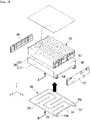
- Fig. 2 is an exploded perspective view of the battery module according to an embodiment of the present disclosure.
- the battery module includes a battery cell stack 100 in which a plurality of battery cells are stacked, a module frame 200 for accommodating the battery cell stack 100; and a cooling plate 300 located on a lower side of the module frame to cool the plurality of battery cells.
- the battery cell according to the embodiment of the present disclosure is a secondary battery and may be configured into a pouch-type secondary battery.
- a battery cell may be composed of a plurality of cells, and the plurality of battery cells may be mutually stacked so as to be electrically connected to each other, thereby forming the battery cell stack 100.
- Each of the plurality of battery cells may include an electrode assembly, a cell case, and an electrode lead protruding from the electrode assembly.
- the module frame 200 accommodates the battery cell stack 100.
- the module frame 200 may include a lower frame 210 for covering the lower surface and both side surfaces of the battery cell stack 100, and an upper plate 220 for covering the upper surface of the battery cell stack 100.
- the structure of the module frame 200 is not limited thereto, and may be a mono frame shape surrounded by four surfaces except the front and rear surfaces of the battery cell stack 100.
- the battery module according to the embodiment of the present disclosure may further include end plates 400 for covering the front and rear surfaces of the battery cell stack 100.
- the battery cell stack 100 accommodated therein can be physically protected through the module frame 200 described above.
- the cooling plate 300 may be formed at the lower part of the module frame 200.
- the cooling plate 300 may include a frame part 310 forming a skeleton of the cooling plate 300 and contacting with the bottom part 211 of the module frame 200, an inlet part 320 formed on one side of the cooling plate 300 to supply a refrigerant from the outside to the inside, an outlet part 330 formed on one side of the heat sink so that the refrigerant flowing inside the heat sink flows to the outside of the heat sink, and a flow passage part 340 that connects the inlet part 320 and the outlet part 330 and allows the refrigerant to flow.
- a cooling integrated heat sink structure may be formed in which the cooling plate 300 on the lower side and the bottom part 211 of the module frame on the upper side are arranged up and down, and the refrigerant flows through the flow passage part 340 formed therebetween.
- the flow passage part 340 may refer to a structure in which a frame part 310 in contact with the lower surface of the lower frame 210 corresponding to the bottom part of the module frame 200 is formed to be depressed downward.
- the upper side of the flow passage part 340 is opened, so that a flow passage is formed between the flow passage part 340 and the bottom part 211 of the module frame 200, and a refrigerant can flow through the flow passage.
- the battery module according to the embodiment of the present disclosure can have a cooling integrated structure in which the bottom part 211 of the module frame 200 serves to correspond to the upper plate of the cooling plate 300.
- the refrigerant can flow directly between the flow passage part 340 of the cooling plate 300 and the bottom part 211 of the module frame 200, thereby increasing the cooling efficiency due to direct cooling, and through a structure in which the cooling plate 300 is integrated with the bottom part of the module frame 200, the space utilization rate on a battery module and a battery pack on which the battery module is mounted can be further improved.
- the frame part 310 may be formed so as to correspond to the bottom part of the module frame 200.
- the bottom part 211 of the module frame 200 corresponds to the bottom part of the lower frame 210, the frame part 310 and the bottom part of the lower frame 210 may be coupled by welding, etc.
- the rigidity of the entire battery module may be reinforced through the frame part 310.
- the frame part 310 and the bottom part of the lower frame 210 are sealed through weld-coupling, whereby a refrigerant can flow without leakage in the flow passage part 340 formed inside the frame part 310.
- Both the inlet part 320 and the outlet part 330 can be formed on one side of the cooling plate 300. More specifically, both the inlet part 320 and the outlet part 330 may be formed on one side of the cooling plate 300 that is formed at a portion at which the end plate 230 is located. The inlet part 320 and the outlet part 330 may be respectively located at both ends of one side of the cooling plate 300.
- a refrigerant supply part and a refrigerant discharge part are formed on the lower or upper side of the cooling plate 300, so that the refrigerant supplied through the refrigerant supply part may flow into the inlet part 320, and the refrigerant flowing out through the outlet part 330 may be discharged to the outside through the refrigerant discharge part.
- the flow passage part 340 may be formed so as to cover the bottom part of the module frame 200 while being bent.
- the flow passage part 340 is formed in most of areas of the bottom part of the module frame 200 excluding a portion in which the frame part 310 makes contact with the bottom part of the module frame 200, whereby all the portions of the battery cell stack 100, which are arranged so as to occupy most of areas of the bottom part of the module frame 200, can be uniformly cooled.
- the portion at which the flow passage part 340 is bent may be formed of a curved surface.
- angled edge portions are formed in the flow passage part 340, it is likely that a flow of the refrigerant will stagnate at the angled edge portions, thus increasing a temperature deviation and a pressure drop.
- the bending part is treated with curved surfaces as in the embodiment of the present disclosure, the flow of the refrigerant can be made naturally.
- Fig. 3 is a diagram showing a case in which an assembly line of a heat sink does not align as a comparative example.
- Fig. 4 is a section A in Fig. 2 , which is a diagram showing a first guide part according to an embodiment of the present disclosure.
- Fig. 5 is a section A in Fig. 2 , which is a diagram showing a second guide part according to an embodiment of the present disclosure.
- a guide part 2110 is formed on the bottom part 211 of the module frame 200, and the cooling plate 300 is coupled to the bottom part 211 of the module frame 200 to so as to correspond to the guide part 2110.
- the guide part 2110 is formed on the bottom part 211 of the module frame, and the cooling plate 300 is assembled to align with the guide part 2110, thereby improving assembly properties, preventing refrigerant leakage, and improving the quality of the battery module.
- the guide part 2110 may include a first guide part 2111 formed at both side ends of the module frame bottom part 211 and a second guide part 2112 formed in a groove shape on the rear end edge side of the module frame bottom part 211.
- Fig. 4 is a diagram showing a first guide part according to an embodiment of the present disclosure.
- Fig. 6 is a section A in Fig. 2 , which is a diagram showing the first guide part when the cooling plate is coupled to the bottom part of the module frame.
- the first guide part 2111 may be engraved in parallel with the edge sides 211a of both side ends at both side ends of the module frame bottom part 211.
- the first guide part 2111 can be arranged so as to align with both sides 300a of the cooling plate 300 as shown in Fig. 6 .
- the cooling plate 300 may be symmetrically arranged with respect to both side ends of the module frame bottom part 211 through the first guide part 2111.
- Fig. 5 is a diagram showing a second guide part according to an embodiment of the present disclosure.
- Fig. 7 is a section B in Fig. 2 , which is a diagram showing the second guide part when the cooling plate is coupled to the bottom part of the module frame.
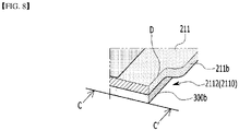
- Fig. 8 is a diagram showing a section taken line C-C' in Fig. 7 .
- the second guide part 2112 may be formed in a groove shape on the rear end edge side 211b of the module frame bottom 211.
- the depression line D of the second guide part 2112 may be arranged so as to align with the rear side 300b of the cooling plate 300 as shown in Figs. 7 and 8 .
- the groove-shaped second guide part 2112 is formed in a plurality of grooves, and the depression lines D of the plurality of grooves may be located on the same line.
- the cooling plate 300 may be arranged so as to correspond to the rear edge of the module frame bottom part 211 through the second guide part 2112.
- the cooling plate 300 can be accurately assembled at a desired position and angle of the module frame bottom part 211 through the first and second guide parts 2111 and 2112 described above.
- a method of manufacturing a battery module includes a step of making both sides 300a of the cooling plate 300 correspond to first guide parts 2111 formed at both side ends of the bottom part 211 of the module frame ( Fig. 6 ), a step of making a rear side 300b of the cooling plate correspond to a second guide part 2112 formed to be depressed at a rear end of the bottom part of the module frame ( Fig. 7 ), and a step of coupling the cooling plate 300 to the bottom part 211 of the module frame.
- both sides 300a of the cooling plate 300 in the step of making both sides 300a of the cooling plate 300 correspond to first guide parts 2111, both sides 300a of the cooling plate 300 can be aligned with the guide part lines formed by the first guide parts 2111.
- the rear side 300b of the cooling plate 300 can be aligned with a depression line D of the second guide part 2112.
- the cooling plate 300 is assembled by aligning the lines formed by the first and second guide parts 2111 and 2112, so that the cooling plate 300 can be precisely arranged at positions corresponding to the edges of the module frame bottom part 211.
- the frame part 310 of the cooling plate 300 can be weld-coupled to the bottom part 311 of the module frame.
- the cooling plate 300 and the module frame bottom part 211 can be sealed and coupled to prevent leakage of the refrigerant flowing therein.
- the above-mentioned battery module can be included in the battery pack.
- the battery pack may have a structure in which one or more of the battery modules according to the embodiment of the present disclosure are gathered, and packed together with a battery management system (BMS) and a cooling device that control and manage battery's temperature, voltage, etc.
- BMS battery management system
- the battery pack can be applied to various devices.
- a device may be applied to a vehicle means such as an electric bicycle, an electric vehicle, or a hybrid vehicle, but the present disclosure is not limited thereto, and is applicable to various devices that can use a battery module, which also belongs to the scope of the present disclosure.
Landscapes
- Chemical & Material Sciences (AREA)
- Chemical Kinetics & Catalysis (AREA)
- Electrochemistry (AREA)
- General Chemical & Material Sciences (AREA)
- Engineering & Computer Science (AREA)
- Manufacturing & Machinery (AREA)
- Aviation & Aerospace Engineering (AREA)
- Battery Mounting, Suspending (AREA)
- Secondary Cells (AREA)
Applications Claiming Priority (2)
| Application Number | Priority Date | Filing Date | Title |
|---|---|---|---|
| KR1020200048917A KR102951964B1 (ko) | 2020-04-22 | 2020-04-22 | 전지 모듈 및 그 제조 방법 |
| PCT/KR2021/004058 WO2021215691A1 (ko) | 2020-04-22 | 2021-04-01 | 전지 모듈 및 그 제조 방법 |
Publications (2)
| Publication Number | Publication Date |
|---|---|
| EP3975320A1 true EP3975320A1 (de) | 2022-03-30 |
| EP3975320A4 EP3975320A4 (de) | 2022-09-21 |
Family
ID=78269679
Family Applications (1)
| Application Number | Title | Priority Date | Filing Date |
|---|---|---|---|
| EP21792184.0A Pending EP3975320A4 (de) | 2020-04-22 | 2021-04-01 | Batteriemodul und herstellungsverfahren dafür |
Country Status (6)
| Country | Link |
|---|---|
| US (1) | US20220247011A1 (de) |
| EP (1) | EP3975320A4 (de) |
| JP (1) | JP7423127B2 (de) |
| KR (1) | KR102951964B1 (de) |
| CN (1) | CN114051669B (de) |
| WO (1) | WO2021215691A1 (de) |
Families Citing this family (1)
| Publication number | Priority date | Publication date | Assignee | Title |
|---|---|---|---|---|
| WO2024262432A1 (ja) * | 2023-06-19 | 2024-12-26 | 株式会社三五 | 蓄電装置 |
Family Cites Families (25)
| Publication number | Priority date | Publication date | Assignee | Title |
|---|---|---|---|---|
| WO2003026049A2 (en) * | 2001-09-18 | 2003-03-27 | Dupont Canada Inc. | Modular fuel cell cartridge and stack |
| DE102008059961B4 (de) * | 2008-12-02 | 2014-08-28 | Daimler Ag | Batterie, umfassend einen Zellverbund aus mehreren parallel und/oder seriell miteinander verschalteten Einzelzellen |
| DE102009040814A1 (de) * | 2009-09-10 | 2011-03-17 | Behr Gmbh & Co. Kg | Verfahren zur Herstellung eines Energiespeicherhalters für ein Fahrzeug |
| JP5513445B2 (ja) * | 2011-06-08 | 2014-06-04 | 本田技研工業株式会社 | 車両用電源装置 |
| DE102011080813A1 (de) * | 2011-08-11 | 2013-02-14 | Behr Gmbh & Co. Kg | Vorrichtung zur Temperierung eines Energiespeichers insbesondere für ein Fahrzeug und Verfahren zum Herstellen derselben |
| KR101288121B1 (ko) * | 2011-08-24 | 2013-07-19 | 삼성에스디아이 주식회사 | 이차전지 및 이차전지 모듈 |
| JP5624015B2 (ja) * | 2011-12-09 | 2014-11-12 | 本田技研工業株式会社 | バッテリの冷却装置 |
| KR101447057B1 (ko) * | 2012-01-26 | 2014-10-07 | 주식회사 엘지화학 | 전지셀의 장착 및 방열을 위한 방열 지지부재를 포함하는 전지모듈 |
| GB2502977B (en) * | 2012-06-11 | 2015-07-15 | Jaguar Land Rover Ltd | A vehicle battery pack, a system for cooling a battery pack and a cooling plate for use in the system |
| DE102012221503B4 (de) * | 2012-11-23 | 2022-01-05 | Vitesco Technologies GmbH | Energiespeicher mit einer Vielzahl von Energiespeicherzellen und mit einem Gehäuse sowie Verfahren zum Herstellen eines Energiespeichers |
| JP6286212B2 (ja) * | 2014-01-20 | 2018-02-28 | ダイキョーニシカワ株式会社 | 電池モジュール |
| KR102198000B1 (ko) * | 2014-02-17 | 2021-01-04 | 삼성에스디아이 주식회사 | 배터리 팩용 케이스 |
| KR102211192B1 (ko) * | 2014-05-30 | 2021-02-02 | 에스케이이노베이션 주식회사 | 단위전지모듈, 전지모듈과 전지팩 및 이들의 제조방법 |
| DE112015002995T5 (de) * | 2014-06-27 | 2017-03-16 | Dana Canada Corporation | Mehrseitige Wärmetauscher mit nachgiebigen Wärmeübertragungsflächen |
| KR101774017B1 (ko) * | 2015-01-13 | 2017-09-01 | 주식회사 엘지화학 | 이차 전지용 카트리지 및 이를 포함하는 배터리 모듈 |
| KR101865995B1 (ko) * | 2015-03-27 | 2018-06-08 | 주식회사 엘지화학 | 배터리 모듈 |
| KR102026386B1 (ko) * | 2015-06-03 | 2019-09-27 | 주식회사 엘지화학 | 배터리 모듈 |
| KR102005488B1 (ko) * | 2015-06-16 | 2019-10-01 | 주식회사 엘지화학 | 이차 전지용 셀 커버 및 이를 포함하는 배터리 모듈 |
| KR101937943B1 (ko) * | 2015-09-02 | 2019-01-11 | 주식회사 엘지화학 | 이차 전지용 카트리지 |
| JP6494870B2 (ja) * | 2015-09-08 | 2019-04-03 | エルジー・ケム・リミテッド | 冷却性能の改善したバッテリーモジュール |
| JP2018181749A (ja) * | 2017-04-20 | 2018-11-15 | 株式会社Fts | バッテリーケース |
| DE102017220862A1 (de) * | 2017-11-22 | 2019-05-23 | Audi Ag | Verfahren zum Herstellen eines Kühlsystems |
| KR102373774B1 (ko) * | 2018-08-21 | 2022-03-14 | 에스케이온 주식회사 | 배터리 모듈 및 이를 포함하는 배터리 팩 |
| CN209071410U (zh) * | 2018-10-25 | 2019-07-05 | 郑州深澜动力科技有限公司 | 一种液冷电池箱体 |
| CN209217042U (zh) * | 2018-11-02 | 2019-08-06 | 陕西科技大学 | 一种可组合式动力电池包 |
-
2020
- 2020-04-22 KR KR1020200048917A patent/KR102951964B1/ko active Active
-
2021
- 2021-04-01 EP EP21792184.0A patent/EP3975320A4/de active Pending
- 2021-04-01 CN CN202180004266.1A patent/CN114051669B/zh active Active
- 2021-04-01 US US17/623,721 patent/US20220247011A1/en active Pending
- 2021-04-01 WO PCT/KR2021/004058 patent/WO2021215691A1/ko not_active Ceased
- 2021-04-01 JP JP2021575021A patent/JP7423127B2/ja active Active
Also Published As
| Publication number | Publication date |
|---|---|
| JP7423127B2 (ja) | 2024-01-29 |
| EP3975320A4 (de) | 2022-09-21 |
| WO2021215691A1 (ko) | 2021-10-28 |
| CN114051669A (zh) | 2022-02-15 |
| KR20210130550A (ko) | 2021-11-01 |
| KR102951964B1 (ko) | 2026-04-10 |
| JP2022537990A (ja) | 2022-08-31 |
| US20220247011A1 (en) | 2022-08-04 |
| CN114051669B (zh) | 2024-07-05 |
Similar Documents
| Publication | Publication Date | Title |
|---|---|---|
| EP3972032A1 (de) | Batteriemodul und batteriepack damit | |
| KR102892942B1 (ko) | 전지팩 | |
| EP4016702A1 (de) | Batteriemodul und batteriepack damit | |
| EP3836293A1 (de) | Batteriemodul und batteriepack damit | |
| EP4016703A1 (de) | Batteriemodul und batteriepack damit | |
| EP4016704B1 (de) | Batteriepack und vorrichtung damit | |
| US12525678B2 (en) | Battery module and battery pack including the same | |
| EP3972034A1 (de) | Batteriemodul und batteriepack damit | |
| EP4210154A1 (de) | Batteriepack und vorrichtung damit | |
| US20210320362A1 (en) | Battery module and manufacturing method thereof | |
| EP4020685A1 (de) | Batteriemodul und herstellungsverfahren dafür | |
| EP4020669A1 (de) | Batteriemodul und herstellungsverfahren dafür | |
| US20220247011A1 (en) | Battery module and manufacturing method thereof | |
| EP4020684A1 (de) | Batteriemodul und herstellungsverfahren dafür | |
| US20220278412A1 (en) | Battery Module and Manufacturing Method Thereof | |
| US12283679B2 (en) | Battery module and battery pack including the same | |
| KR102941247B1 (ko) | 전지 모듈 및 그 제조 방법 |
Legal Events
| Date | Code | Title | Description |
|---|---|---|---|
| STAA | Information on the status of an ep patent application or granted ep patent |
Free format text: STATUS: THE INTERNATIONAL PUBLICATION HAS BEEN MADE |
|
| PUAI | Public reference made under article 153(3) epc to a published international application that has entered the european phase |
Free format text: ORIGINAL CODE: 0009012 |
|
| STAA | Information on the status of an ep patent application or granted ep patent |
Free format text: STATUS: REQUEST FOR EXAMINATION WAS MADE |
|
| 17P | Request for examination filed |
Effective date: 20211223 |
|
| AK | Designated contracting states |
Kind code of ref document: A1 Designated state(s): AL AT BE BG CH CY CZ DE DK EE ES FI FR GB GR HR HU IE IS IT LI LT LU LV MC MK MT NL NO PL PT RO RS SE SI SK SM TR |
|
| A4 | Supplementary search report drawn up and despatched |
Effective date: 20220819 |
|
| RIC1 | Information provided on ipc code assigned before grant |
Ipc: H01M 50/20 20210101ALI20220812BHEP Ipc: H01M 10/613 20140101ALI20220812BHEP Ipc: H01M 10/6551 20140101ALI20220812BHEP Ipc: H01M 10/6554 20140101AFI20220812BHEP |
|
| DAV | Request for validation of the european patent (deleted) | ||
| DAX | Request for extension of the european patent (deleted) | ||
| STAA | Information on the status of an ep patent application or granted ep patent |
Free format text: STATUS: EXAMINATION IS IN PROGRESS |
|
| 17Q | First examination report despatched |
Effective date: 20240202 |