EP3975461B1 - Procédé et appareil de détermination de ressources - Google Patents
Procédé et appareil de détermination de ressources Download PDFInfo
- Publication number
- EP3975461B1 EP3975461B1 EP20833510.9A EP20833510A EP3975461B1 EP 3975461 B1 EP3975461 B1 EP 3975461B1 EP 20833510 A EP20833510 A EP 20833510A EP 3975461 B1 EP3975461 B1 EP 3975461B1
- Authority
- EP
- European Patent Office
- Prior art keywords
- ofdm symbol
- reference signal
- channel measurement
- measurement reference
- dmrs
- Prior art date
- Legal status (The legal status is an assumption and is not a legal conclusion. Google has not performed a legal analysis and makes no representation as to the accuracy of the status listed.)
- Active
Links
Images



Classifications
-
- H—ELECTRICITY
- H04—ELECTRIC COMMUNICATION TECHNIQUE
- H04L—TRANSMISSION OF DIGITAL INFORMATION, e.g. TELEGRAPHIC COMMUNICATION
- H04L5/00—Arrangements affording multiple use of the transmission path
- H04L5/003—Arrangements for allocating sub-channels of the transmission path
- H04L5/0048—Allocation of pilot signals, i.e. of signals known to the receiver
- H04L5/0051—Allocation of pilot signals, i.e. of signals known to the receiver of dedicated pilots, i.e. pilots destined for a single user or terminal
-
- H—ELECTRICITY
- H04—ELECTRIC COMMUNICATION TECHNIQUE
- H04L—TRANSMISSION OF DIGITAL INFORMATION, e.g. TELEGRAPHIC COMMUNICATION
- H04L5/00—Arrangements affording multiple use of the transmission path
- H04L5/0001—Arrangements for dividing the transmission path
- H04L5/0003—Two-dimensional division
- H04L5/0005—Time-frequency
- H04L5/0007—Time-frequency the frequencies being orthogonal, e.g. OFDM(A) or DMT
-
- H—ELECTRICITY
- H04—ELECTRIC COMMUNICATION TECHNIQUE
- H04W—WIRELESS COMMUNICATION NETWORKS
- H04W72/00—Local resource management
- H04W72/04—Wireless resource allocation
- H04W72/044—Wireless resource allocation based on the type of the allocated resource
- H04W72/0446—Resources in time domain, e.g. slots or frames
-
- H—ELECTRICITY
- H04—ELECTRIC COMMUNICATION TECHNIQUE
- H04W—WIRELESS COMMUNICATION NETWORKS
- H04W72/00—Local resource management
- H04W72/04—Wireless resource allocation
- H04W72/044—Wireless resource allocation based on the type of the allocated resource
- H04W72/0453—Resources in frequency domain, e.g. a carrier in FDMA
-
- H—ELECTRICITY
- H04—ELECTRIC COMMUNICATION TECHNIQUE
- H04L—TRANSMISSION OF DIGITAL INFORMATION, e.g. TELEGRAPHIC COMMUNICATION
- H04L5/00—Arrangements affording multiple use of the transmission path
- H04L5/003—Arrangements for allocating sub-channels of the transmission path
- H04L5/0053—Allocation of signalling, i.e. of overhead other than pilot signals
Definitions
- This application relates to the field of communication technologies, and in particular, to a resource determining method and an apparatus.
- a communication system usually uses an intra-frequency networking manner. That is, a plurality of cells in a network may be deployed in a same frequency band. In this way, when a user is at an edge of a serving cell, the user may be subject to co-channel interference from a neighboring cell of the serving cell. Consequently, quality of service and a throughput of the edge user are severely limited. Therefore, to resolve a problem of interference between cells, a coordinated multipoint transmission/reception (coordinated multipoint transmission/reception, CoMP) technology is widely applied.
- CoMP coordinated multipoint transmission/reception
- the coordinated multipoint transmission/reception technology specifically means that a plurality of transmission reception points (transmission reception points, TRPs) cooperate to transmit data to one terminal, or the plurality of TRPs jointly receive data sent by the terminal. Based on an information exchange delay between the plurality of TRPs, CoMP transmission may be classified into ideal backhaul (ideal backhaul, IB) and non-ideal backhaul (non-ideal backhaul, NIB).
- ideal backhaul ideal backhaul, IB
- non-ideal backhaul non-ideal backhaul
- a mechanism of separately delivering downlink control information (downlink control information, DCI) independently by the plurality of TRPs to independently schedule a physical downlink shared channel (physical downlink shared channel, PDSCH) and a demodulation reference signal (demodulation reference signal, DMRS) of the terminal is introduced to ensure performance of the communication system.
- DCI downlink control information
- PDSCH physical downlink shared channel
- DMRS demodulation reference signal
- a plurality of TRPs in a coordinated set may each have a configuration in which an LTE base station and an NR base station are co-sited.
- cell-specific reference signal (cell-specific reference signal, CRS) configuration information is separately configured for each TRP, to indicate a time-frequency resource occupied by a CRS of the TRP.
- CRS cell-specific reference signal
- a DMRS corresponding to a PDSCH independently scheduled by a TRP may be migrated in time domain to avoid an orthogonal frequency division multiplexing (orthogonal frequency division multiplexing, OFDM) symbol occupied by a CRS of the TRP.
- OFDM orthogonal frequency division multiplexing
- EP 3 276 849 Al refers to a 5G or pre-5G communication system for supporting a higher data transmission rate beyond a 4G communication system such as LTE.
- a base station using a large-scale antenna transmits, to a terminal, reference signal resource configuration information including multiple pieces of reference signal configuration information and reference signal port information, for transmission of a reference signal, and transmits the reference signal to the terminal using some or all of channel measurement resources indicated by the multiple pieces of reference signal configuration information and the reference signal port information included in the reference signal resource configuration information.
- the channel measurement resources may correspond to antenna ports, the number of which is indicated by a combination of the multiple pieces of reference signal configuration information and the reference signal port information.
- CN 102 857 458 B refers to a pilot frequency symbol determining method comprising the steps of allocating different demodulation reference signals (DMRS) for data resource in different packets and carrying out precoding or beam forming processing on the data resource in different packets by utilizing different precoding weights or beam forming weights, wherein different DMRS packets are carried on one or more than one of a second OFDM (orthogonal frequency division multiplexing) symbol, a fourth OFDM symbol, a fifth OFDM symbol and an eighth OFDM symbol of an extension circulation prefix subframe.
- DMRS demodulation reference signals
- A/B may represent A or B.
- “And/or” in this specification describes only an association relationship between associated objects and represents that there may be three relationships.
- a and/or B may represent the following three cases: Only A exists, both A and B exist, and only B exists.
- "at least one” means one or more, and "a plurality of” means two or more. Terms such as “first” and “second” do not limit a quantity and an execution sequence, and the terms such as “first” and “second” do not indicate a definite difference either.
- one slot includes 14 OFDM symbols.
- one slot includes 12 OFDM symbols.
- one slot includes 14 OFDM symbols.
- 14 OFDM symbols are sequentially numbered in chronological order from front to back, an earliest OFDM symbol is numbered 0, and a latest OFDM symbol is numbered 13.
- the slot includes the OFDM symbol #0 to the OFDM symbol #13.
- the subframe includes 14 OFDM symbols.
- 14 OFDM symbols are sequentially numbered in chronological order from front to back, an earliest OFDM symbol is numbered 0, and a latest OFDM symbol is numbered 13.
- the subframe includes the OFDM symbol #0 to the OFDM symbol #13.
- the slot in NR is equivalent to the subframe in LTE.
- the QCL information is used to assist in describing beamforming information and a receiving procedure on a receive side of a terminal, represents a large-scale feature of a channel, is usually a long-term observation value, and may further represent receive beam information.
- four types of the QCL information are defined in an existing standard, and are:
- CDM code division multiplexing
- the CDM group includes a plurality of antenna ports.
- a plurality of antenna ports in a same CDM group share a same time-frequency resource, and the plurality of antenna ports in the same CDM group are distinguished in a form of code division, that is, code domain resources of sequences of the plurality of antenna ports in the same CDM group are different.
- the code domain resource is usually an orthogonal code, for example, an orthogonal cover code (orthogonal cover code, OCC).
- OCC code may be used in time domain, frequency domain, space domain (beam domain), and the like.
- Control resource set control resource set, CORESET
- control resource set group control resource set group
- the control resource set group may include one or more control resource sets.
- the terminal may perform channel estimation based on the DMRS, and a result of the channel estimation may be used to receive and demodulate a PDSCH corresponding to the DMRS.
- the DMRS occupies some OFDM symbols on the PDSCH. In other words, the some OFDM symbols on the PDSCH are used to carry the DMRS.
- a base station schedules a time-frequency resource of the PDSCH by using DCI.
- the base station and the terminal pre-agree on positions of time-frequency resources that are on the PDSCH and that are occupied by the DMRS, and the DCI also includes position information of the DMRS.
- the terminal finally determines, based on a pre-agreed position relationship between the PDSCH and the time-frequency resources occupied by the DMRS and the DMRS position information indicated in the DCI, the time-frequency resource occupied by the DMRS.
- the DMRS includes two types: One is a single-symbol (single-symbol) DMRS, and the other is a double-symbol (double-symbol) DMRS.
- the single-symbol DMRS means that a quantity of consecutive OFDM symbols occupied by the DMRS is 1.
- the double-symbol DMRS means that a quantity of consecutive OFDM symbols occupied by the DMRS is 2.
- the following uses the single-symbol DMRS as an example for description.
- DMRSs may be classified into a front-loaded DMRS (front-loaded DMRS) and an additional DMRS (additional DMRS) based on positions of OFDM symbols on a PDSCH and occupied by the DMRSs.
- front-loaded DMRS front-loaded DMRS
- additional DMRS additional DMRS
- the front-loaded DMRS occupies the first OFDM symbol on the PDSCH.
- the terminal may determine the first OFDM symbol on the PDSCH based on a time domain position that is of the PDSCH and that is indicated in DCI, to determine a position of the OFDM symbol occupied by the front-loaded DMRS.
- the PDSCH includes the additional DMRS only when the base station configures, by using higher layer signaling such as RRC signaling, that there is the additional DMRS.
- the higher layer signaling also indicates a quantity of additional DMRSs.
- the quantity may be 1, 2, or 3.
- a position of an OFDM symbol occupied by the additional DMRS is determined based on the quantity of additional DMRSs configured by using the RRC signaling and a corresponding length of the PDSCH in one slot.
- the length of the PDSCH in the slot is a quantity of OFDM symbols occupied by the PDSCH in the slot.
- the additional DMRS occupies at least one of the last two of the OFDM symbols occupied by the PDSCH.
- the quantity of additional DMRSs is 2 or 3
- l d is a quantity of OFDM symbols between the first OFDM symbol in a slot and the last OFDM symbol in a time domain resource of a PDSCH.
- l 0 is used to indicate a position of the first OFDM symbol occupied by the DMRS.
- l 0 2 or 3
- l 0 3
- the first OFDM symbol occupied by the DMRS is an OFDM symbol #3 in the slot.
- l 0 3
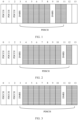
- a position of the DMRS may be shown in FIG. 1 .
- a position of the DMRS may be shown in FIG. 2 .
- time domain positions of the PDSCHs scheduled by the two base stations need to be limited, to ensure that DMRSs on PDSCHs of a plurality of TRPs are aligned in time domain to ensure performance of DMRS-based channel estimation.
- a quantity of OFDM symbols on the other PDSCH is also X if a quantity of OFDM symbols on one PDSCH is X.
- start positions of the PDSCHs in time domain need to be consistent, so that the DMRSs (including a front-loaded DMRS and the additional DMRS) corresponding to the two PDSCHs occupy same OFDM symbols.
- X may be selected from 12 to 14.
- the DMRS corresponding to the PDSCH is a DMRS used to demodulate the PDSCH.
- An OFDM symbol occupied by the DMRS corresponding to the PDSCH is located on a time domain resource of the PDSCH.
- the PDSCH corresponding to the DMRS is a PDSCH demodulated by using the DMRS.
- a time domain resource of the PDSCH corresponding to the DMRS includes an OFDM symbol occupied by the DMRS.
- the CRS is used to implement functions such as performing channel estimation on a downlink physical channel to demodulate data information and performing channel measurement so that the terminal obtains CSI information and reports the CSI information to the base station.
- the CRS supports configurations of one, two, and four antenna ports.
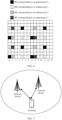
- FIG. 4 shows a resource pattern of a CRS supporting one antenna port.
- the CRS occupies an OFDM symbol #0, an OFDM symbol #4, an OFDM symbol #7, and an OFDM symbol #11 in a subframe.
- FIG. 5 shows a resource pattern of a CRS supporting two antenna ports.
- the CRS occupies an OFDM symbol #0, an OFDM symbol #4, an OFDM symbol #7, and an OFDM symbol #11 in a subframe.
- FIG. 6 shows a resource pattern of a CRS supporting four antenna ports.
- the CRS occupies an OFDM symbol #0, an OFDM symbol #2, an OFDM symbol #4, an OFDM symbol #7, an OFDM symbol #8, and an OFDM symbol #11 in a subframe.
- a set of independent CRS configuration parameters needs to be separately configured for the plurality of TRPs. For example, that CRSs occupy different slots, that the CRSs occupy different OFDM symbols, and/or that the CRSs occupy different RBs and a subcarrier in each RB may be configured for different TRPs. That CRS configuration parameters are independently configured for the different TRPs represents that serving cells corresponding to the different TRPs use time-frequency resource patterns of different CRSs. Different CRS configuration parameters may be configured by using independent RRC signaling, or may be configured by using same RRC signaling. For example, if there is one master TRP (master TRP) in the plurality of TRPs in the coordinated set, the master TRP may send RRC signaling to another TRP, to configure a set of independent CRS configuration parameters for the another TRP.
- master TRP master TRP
- the master TRP may send RRC signaling to another TRP, to configure a set of independent CRS configuration parameters for the another TRP.
- DMRSs corresponding to PDSCHs independently scheduled by the plurality of TRPs may be aligned in time domain.
- a TRP #1 and a TRP #2 form a coordinated set to serve one terminal together.
- the TPR 1 schedules a PDSCH #1 by using DCI delivered on a CORESET 1
- the TRP #2 schedules a PDSCH #2 by using DCI delivered on a CORESET 2
- OFDM symbol lengths of the PDSCH #1 and the PDSCH #2 are both 13 or 14.
- a DMRS on the PDSCH #1 is referred to as a DMRS #1
- a DMRS on the PDSCH #2 is referred to as a DMRS #2.
- a quantity of additional DMRSs is 1.
- Configuration information of a CRS #1 corresponds to a time-frequency resource occupied by the TRP #1 to send a CRS 1
- configuration information of a CRS #2 corresponds to a time-frequency resource occupied by the TRP #2 to send a CRS 2. Because the configuration information of the CRS #1 and the configuration information of the CRS #2 are configured by using independent RRC signaling, the configuration information of the CRS #1 and the configuration information of the CRS #2 may be different.
- the configuration information of the CRS #1 indicates that the CRS #1 occupies an OFDM symbol #0, an OFDM symbol #4, an OFDM symbol #7, and an OFDM symbol #11 in a slot #1
- the configuration information of the CRS #2 indicates that the CRS #2 occupies an OFDM symbol #0, an OFDM symbol #4, an OFDM symbol #7, and an OFDM symbol #11 in a slot #2.
- an OFDM symbol occupied by the DMRS #1 is determined based on the configuration information of the CRS #1
- an OFDM symbol occupied by the DMRS #2 is determined based on the configuration information of the CRS #2.
- the OFDM symbol occupied by the DMRS #1 needs to avoid the OFDM symbols occupied by the CRS #1. Therefore, the DMRS #1 occupies an OFDM symbol #12. In the slot 1, because the CRS #2 does not occupy any OFDM symbol, the DMRS #2 may occupy the OFDM symbol #11. In this way, the DMRS #1 and the DMRS #2 are not aligned in time domain. Consequently, performance of DMRS-based channel estimation of the terminal is affected.
- this application provides a resource determining method.
- the method For specific descriptions of the method, refer to the following descriptions.
- the technical solutions provided in the embodiments of this application may be applied to various communication systems, for example, a new radio (new radio, NR) communication system using a 5th generation (5th generation, 5G) communication technology, a future evolved system, or a plurality of convergent communication systems.
- the technical solutions provided in this application may be applied to a plurality of application scenarios, for example, machine to machine (machine to machine, M2M), macro-micro communication, enhanced mobile broadband (enhanced mobile broadband, eMBB), ultra-reliable and low-latency communication (ultra-reliable & low-latency communication, uRLLC), and massive machine-type communications (massive machine-type communications, mMTC).
- These scenarios may include but are not limited to a scenario of communication between communication devices, a scenario of communication between network devices, a scenario of communication between a network device and a communication device, and the like.
- the following provides descriptions by using an example in which the technical solutions are applied to a scenario of communication between a network device and a terminal.
- a network architecture and a service scenario that are described in the embodiments of this application are intended to describe the technical solutions in the embodiments of this application more clearly, and do not constitute a limitation on the technical solutions provided in the embodiments of this application.
- a person of ordinary skill in the art may learn that with evolution of the network architecture and emergence of a new service scenario, the technical solutions provided in the embodiments of this application are also applicable to similar technical problems.
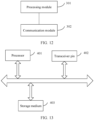
- FIG. 7 is a schematic diagram of an architecture of a communication system to which the technical solutions provided in this application are applicable.
- the communication system may include a plurality of network devices ( FIG. 7 shows only two network devices) and one or more terminals ( FIG. 7 shows only one terminal). As shown in FIG. 7 , the two network devices may simultaneously communicate with the terminal.
- the network device may be a base station, a base station controller, or the like in wireless communication.
- the base station may include various types of base stations, such as a micro base station (also referred to as a small cell), a macro base station, a relay station, and an access point. This is not specifically limited in the embodiments of this application.
- the base station may be a base transceiver station (base transceiver station, BTS) in a global system for mobile communications (global system for mobile communications, GSM) or code division multiple access (code division multiple access, CDMA), a NodeB (NodeB) in wideband code division multiple access (wideband code division multiple access, WCDMA), an evolved NodeB (evolved NodeB, eNB or eNodeB) in long term evolution (long term evolution, LTE), an eNB in an internet of things (internet of things, IoT) or an narrowband internet of things (narrow-band internet of things, NB-IoT), or a base station in a future 5G mobile communication network or a future evolved public land mobile network (public land mobile network, PLMN).
- GSM global system for mobile communications
- CDMA code division multiple access
- NodeB wideband code division multiple access
- WCDMA wideband code division multiple access
- WCDMA wideband code division multiple access
- eNodeB
- an apparatus configured to implement a function of the network device may be a network device, or may be an apparatus, for example, a chip system, that can support the network device in implementing the function.
- an example in which the apparatus configured to implement the function of the network device is the network device is used to describe the technical solutions provided in the embodiments of this application.
- the network device described in this application usually includes a baseband unit (baseband unit, BBU), a remote radio unit (remote radio unit, RRU), an antenna, and a feeder used to connect the RRU and the antenna.
- BBU baseband unit
- RRU remote radio unit
- the BBU is configured to be responsible for signal modulation.
- the RRU is configured to be responsible for radio frequency processing.
- the antenna is configured to be responsible for conversion between a pilot wave on a cable and a space wave in the air.
- a distributed base station greatly shortens a length of the feeder between the RRU and the antenna, to reduce a signal loss, and reduce costs of the feeder.
- the RRU and the antenna are relatively small and can be installed anywhere, making network planning more flexible.
- the RRU may be remotely placed.
- all BBUs may be centralized and placed in a central office (Central Office, CO).
- Central Office Central Office
- a quantity of base station equipment rooms can be greatly reduced, energy consumption of auxiliary devices, especially air conditioners, can be reduced, and carbon emission can be greatly reduced.
- the BBUs can be managed and scheduled centrally, and resources can be allocated more flexibly.
- all physical base stations evolve into virtual base stations. All the virtual base stations share information such as data sent and received by users and channel quality in the BBU baseband pool, and cooperate with each other, to implement joint scheduling.
- the base station may include a centralized unit (centralized unit, CU) and a distributed unit (Distributed Unit, DU).
- the base station may further include an active antenna unit (active antenna unit, AAU).
- the CU implements some functions of the base station, and the DU implements some functions of the base station.
- the CU is responsible for processing a non-real-time protocol and service, and implements functions of a radio resource control (radio resource control, RRC) and a packet data convergence protocol (packet data convergence protocol, PDCP) layer.
- RRC radio resource control
- PDCP packet data convergence protocol
- the DU is responsible for processing a physical layer protocol and a real-time service, and implements functions of a radio link control (radio link control, RLC) layer, a media access control (media access control, MAC) layer, and a physical (physical, PHY) layer.
- RLC radio link control
- MAC media access control
- PHY physical (physical, PHY) layer.
- the AAU implements some physical layer processing functions, radio frequency processing, and a function related to an active antenna.
- Information at the RRC layer eventually becomes information at the PHY layer, or is converted from the information at the PHY layer. Therefore, in this architecture, higher layer signaling, for example, RRC layer signaling or PDCP layer signaling, may also be considered as being sent by the DU or sent by the DU and the AAU.
- the terminal device may be a virtual reality (virtual reality, VR) terminal device, an augmented reality (augmented reality, AR) terminal device, a wireless terminal in industrial control, a wireless terminal in self-driving, a wireless terminal in telemedicine, a wireless terminal in a smart grid, a wireless terminal in a smart city (smart city), a wireless terminal in a smart home (smart home), or the like.
- an apparatus configured to implement a function of the terminal may be a terminal, or may be an apparatus, for example, a chip system, that can support the terminal in implementing the function.
- the chip system may include a chip, or may include the chip and another discrete component.
- an example in which the apparatus configured to implement the function of the terminal is the terminal is used to describe the technical solutions provided in the embodiments of this application.
- the communication apparatus includes at least one processor 101, a communication line 102, a memory 103, and at least one communication interface 104.
- the processor 101 may be a general-purpose central processing unit (central processing unit, CPU), a microprocessor, an application-specific integrated circuit (application-specific integrated circuit, ASIC), or one or more integrated circuits configured to control program execution of the solutions in this application.
- CPU central processing unit
- ASIC application-specific integrated circuit
- the communication line 102 may include a path on which information is transferred between the foregoing components.
- the communication interface 104 which uses any apparatus such as a transceiver, is configured to communicate with another device or communication network, such as an ethernet, a RAN, and a wireless local area network (wireless local area network, WLAN).
- another device or communication network such as an ethernet, a RAN, and a wireless local area network (wireless local area network, WLAN).
- WLAN wireless local area network
- the memory 103 may be a read-only memory (read-only memory, ROM) or another type of static storage device that can store static information and instructions, or a random access memory (random access memory, RAM) or another type of dynamic storage device that can store information and instructions, or may be an electrically erasable programmable read-only memory (electrically erasable programmable read-only memory, EEPROM), a compact disc read-only memory (compact disc read-only memory, CD-ROM) or other compact disc storage, optical disc storage (including a compact disc, a laser disc, an optical disc, a digital versatile disc, a Blu-ray disc, or the like), a disk storage medium or another magnetic storage device, or any other medium that can be configured to carry or store expected program code having an instruction or data structure form and that can be accessed by a computer.
- ROM read-only memory
- RAM random access memory
- EEPROM electrically erasable programmable read-only memory
- CD-ROM compact disc read-only memory
- the memory 103 is not limited thereto.
- the memory may exist independently, and is connected to the processor through the communication line 102.
- the memory may alternatively be integrated with the processor.
- the memory provided in this embodiment of this application may usually be non-volatile.
- the memory 103 is configured to store computer-executable instructions for performing the solutions in this application, and the processor 101 controls execution of the computer-executable instructions.
- the processor 101 is configured to execute the computer-executable instructions stored in the memory 103, to implement the methods provided in the following embodiments of this application.
- the computer-executable instructions in this embodiment of this application may also be referred to as application program code. This is not specifically limited in this embodiment of this application.
- the processor 101 may include one or more CPUs such as a CPU 0 and a CPU 1 shown in FIG. 8 .
- the communication apparatus may include a plurality of processors such as the processor 101 and a processor 107 in FIG. 8 .
- Each of the processors may be a single-core (single-CPU) processor or a multi-core (multi-CPU) processor.
- the processor may be one or more devices, circuits, and/or processing cores configured to process data (for example, computer program instructions).
- the communication apparatus may further include an output device 105 and an input device 106.
- the output device 105 communicates with the processor 101, and may display information in a plurality of manners.
- the output device 105 may be a liquid crystal display (liquid crystal display, LCD), a light emitting diode (light emitting diode, LED) display device, a cathode ray tube (cathode ray tube, CRT) display device, or a projector (projector).
- the input device 106 communicates with the processor 101, and may receive an input from a user in a plurality of manners.
- the input device 106 may be a mouse, a keyboard, a touchscreen device, or a sensor device.
- FIG. 9 shows a resource determining method according to an embodiment of this application. The method includes the following steps.
- a communication apparatus obtains N pieces of channel measurement reference signal configuration information.
- the channel measurement reference signal configuration information is used to indicate a resource occupied by a channel measurement reference signal on one carrier/serving cell/bandwidth part.
- the resource occupied by the channel measurement reference signal includes a time-frequency resource.
- the time-frequency resource occupied by the channel measurement reference signal includes an OFDM symbol.
- the time-frequency resource occupied by the channel measurement reference signal includes a plurality of REs.
- the channel measurement reference signal configuration information may include at least one of the following information: a periodicity and an offset in time domain, a quantity and/or positions of OFDM symbols occupied in one slot/subframe, a quantity and/or positions of occupied RBs, a quantity and/or positions of subcarriers occupied in one RB, a quantity and/or positions of REs, or the like.
- the channel measurement reference signal may include one of a CRS, a CSI-RS, an SSB, or an RMR.
- the N pieces of channel measurement reference signal configuration information may be in a one-to-one correspondence with N TRPs. That is, the N pieces of channel measurement reference signal configuration information may be independently configured for the N TRPs.
- N is a positive integer.
- step S101 may be specifically implemented as follows:
- the TRP generates channel measurement reference signal configuration information of the TRP, and the TRP obtains N-1 pieces of channel measurement reference signal configuration information from other TRPs participating in the cooperative transmission; or the TRP obtains the N pieces of channel measurement reference signal configuration information by using another network device (for example, a core network, a management device, or a master TRP).
- another network device for example, a core network, a management device, or a master TRP.
- step S101 may be specifically implemented as follows: The terminal separately receives channel measurement reference signal configuration information sent by each of the N TRPs; or the terminal receives channel measurement reference signal configuration information sent by one or more of the N TRPs, where one TRP may send a plurality of pieces of channel measurement reference signal configuration information.
- the N pieces of channel measurement reference signal configuration information may be received by the terminal in a same time unit, or may be separately received by the terminal in different time units.
- the communication apparatus determines, based on the N pieces of channel measurement reference signal configuration information, an OFDM symbol occupied by a DMRS in a first time unit.
- the first time unit may be a slot, a mini-slot, a subframe, a transmission time interval, or the like in which a PDSCH corresponding to the DMRS is located.
- the first time unit may be a time domain resource occupied by the PDSCH corresponding to the DMRS.
- the PDSCH corresponding to the DMRS is a PDSCH demodulated by using the DMRS. Therefore, the DMRS may also be referred to as a DMRS on the PDSCH or a DMRS corresponding to the PDSCH.
- the communication apparatus may determine, based on one of the N pieces of channel measurement reference signal configuration information, the OFDM symbol occupied by the DMRS in the first time unit.
- the communication apparatus determines, based on the N pieces of channel measurement reference signal configuration information, the OFDM symbol occupied by the DMRS in the first time unit.
- the time domain position occupied by the channel measurement reference signal includes a position of a slot and a position of the OFDM symbol occupied by the channel measurement reference signal in the slot.
- any OFDM symbol occupied by the DMRS does not overlap any OFDM symbol occupied by the channel measurement reference signals and indicated by the N pieces of channel measurement reference signal configuration information, where the OFDM symbol is an OFDM symbol in a specified slot or subframe.
- OFDM symbols occupied by the channel measurement reference signals and indicated by the N pieces of channel measurement reference signal configuration information specifically include an OFDM symbol occupied by the channel measurement reference signal and indicated by each of the N pieces of channel measurement reference signal configuration information.
- the OFDM symbol occupied by the DMRS satisfies the following rules.
- the first OFDM symbol and the second OFDM symbol are two different OFDM symbols in a same slot or subframe.
- the second OFDM symbol may be a preceding OFDM symbol of the first OFDM symbol.
- the first OFDM symbol is an OFDM symbol #11, and the second OFDM symbol is an OFDM symbol #10.
- the second OFDM symbol may be a next OFDM symbol of the first OFDM symbol.
- the first OFDM symbol is an OFDM symbol #11, and the second OFDM symbol is an OFDM symbol #12.
- a position relationship between the first OFDM symbol and the second OFDM symbol is not limited in this embodiment of this application.
- a position of the first OFDM symbol is an optimal position for channel estimation. Therefore, when the first OFDM symbol is not used to carry a CRS, the first OFDM symbol is used to carry a DMRS. However, when the first OFDM symbol is used to carry the CRS, the first OFDM symbol is not used to carry the DMRS to avoid a conflict between the CRS and the DMRS. In this case, the DMRS is migrated from the first OFDM symbol to the second OFDM symbol.
- the first OFDM symbol and the second OFDM symbol are OFDM symbols other than a start OFDM symbol of the PDSCH corresponding to the DMRS. Specifically, if a quantity of consecutive OFDM symbols occupied by the DMRS is 1, that is, the DMRS is a single-symbol DMRS, the first OFDM symbol and the second OFDM symbol are OFDM symbols other than the first OFDM symbol in a time domain resource of the PDSCH.
- the DMRS is a double-symbol DMRS
- the first OFDM symbol and the second OFDM symbol are OFDM symbols other than the first OFDM symbol and the second OFDM symbol in a time domain resource of the PDSCH.
- the first OFDM symbol and the second OFDM symbol are the last two OFDM symbols in the time domain resource of the PDSCH.
- the first time unit is a slot in which the PDSCH corresponding to the DMRS is located, the first OFDM symbol is the eighth OFDM symbol in the first time unit, and the second OFDM symbol is the ninth OFDM symbol in the first time unit, or the second OFDM symbol is the seventh OFDM symbol in the first time unit.
- rule 1 and rule 2 are applicable to various DMRS configurations.
- a quantity of additional DMRSs may be any one of 1 to 4.
- rule 1 and rule 2 may be implemented separately or together. This is not limited in this application.
- the TRP may transmit the PDSCH in the first time unit, and send the DMRS on the OFDM symbol occupied by the DMRS in the first time unit.
- the terminal may receive the DMRS on the OFDM symbol occupied by the DMRS in the first time unit.
- an OFDM symbol occupied by a DMRS of the TRP in the first time unit is determined based on the N pieces of channel measurement reference signal configuration information, instead of being determined based only on channel measurement reference signal configuration information of the TRP.
- impact of channel measurement reference signal configuration information of another TRP is considered, to ensure that the OFDM symbol occupied by the DMRS of the TRP is the same as an OFDM symbol occupied by a DMRS of the another TRP, and performance of DMRS-based channel estimation of the terminal is ensured.
- one or more pieces of channel measurement reference signal configuration information in the N pieces of channel measurement reference signal configuration information are associated with a control resource set, the control resource set is used to carry DCI, and the DCI is used to schedule the PDSCH corresponding to the DMRS; and/or the one or more pieces of channel measurement reference signal configuration information in the N pieces of channel measurement reference signal configuration information are associated with a CDM group occupied by the DMRS.
- the association relationship between the channel measurement reference signal configuration information and the control resource set may also be referred to as a correspondence between the channel measurement reference signal configuration information and the control resource set, for example, a one-to-one correspondence, a one-to-many correspondence, or a many-to-one correspondence between the channel measurement reference signal configuration information and the control resource set. This is not limited in this embodiment of this application.
- the terminal determines, based on channel measurement reference signal configuration information associated with the control resource set, whether to detect the DCI on the control resource set. Specifically, if a position of an RE occupied by a control resource set overlaps a position of an RE occupied by a channel measurement reference signal and indicated by channel measurement reference signal configuration information associated with the control resource set, the terminal does not detect the DCI on the control resource set. Otherwise, the terminal detects the DCI on the control resource set.
- the base station determines a resource configuration of the control resource set based on channel measurement reference signal configuration information associated with the control resource set, where the resource configuration includes a configuration of a time-frequency resource. Specifically, the base station determines that a position of an RE occupied by a control resource set does not overlap a position of an RE occupied by a channel measurement reference signal and indicated by channel measurement reference signal configuration information associated with the control resource set.
- the base station or the terminal can determine, based on channel measurement reference signal configuration information associated with the control resource set, an RE to which a target PDSCH is mapped, where the target PDSCH is a PDSCH scheduled by using DCI carried on the control resource set.
- the target PDSCH is not mapped to an RE occupied by a channel measurement reference signal and indicated by the channel measurement reference signal configuration information associated with the control resource set.
- the base station does not send the target PDSCH on the RE occupied by the channel measurement reference signal and indicated by the channel measurement reference signal configuration information associated with the control resource set.
- the terminal does not receive the PDSCH on the RE occupied by the channel measurement reference signal and indicated by the channel measurement reference signal configuration information associated with the control resource set.
- An association relationship between the channel measurement reference signal configuration information and the CDM group may also be referred to as a correspondence between the channel measurement reference signal configuration information and the CDM group, for example, a one-to-one correspondence, a one-to-many correspondence, or a many-to-one correspondence between the channel measurement reference signal configuration information and the CDM group. This is not limited in this embodiment of this application.
- the base station or the terminal can determine, based on channel measurement reference signal configuration information associated with the CDM group, an RE to which a PDSCH corresponding to the CDM group is mapped, where the PDSCH corresponding to the CDM group is a PDSCH corresponding to a DMRS occupying the CDM group.
- the PDSCH corresponding to the CDM group is not mapped to an RE occupied by a channel measurement reference signal and indicated by the channel measurement reference signal configuration information associated with the CDM group.
- the base station does not send, on the RE occupied by the channel measurement reference signal and indicated by the channel measurement reference signal configuration information associated with the CDM group, the PDSCH corresponding to the CDM group.
- the terminal does not receive, on the RE occupied by the channel measurement reference signal and indicated by the channel measurement reference signal configuration information associated with the CDM group, the PDSCH corresponding to the CDM group.
- the channel measurement reference signal configuration information may include an identifier/index value of the control resource set, to indicate the control resource set associated with the channel measurement reference signal configuration information; and/or the channel measurement reference signal configuration information may include an identifier/index value of the CDM group, to indicate the CDM group associated with the channel measurement reference signal configuration information.
- a network device may send indication information to the terminal, to indicate the control resource set associated with the channel measurement reference signal configuration information and/or the CDM group associated with the channel measurement reference signal configuration information.
- a resource occupied by a channel measurement reference signal and indicated by the one or more pieces of channel measurement reference signal configuration information includes a plurality of REs. It may be understood that one RE occupies one OFDM symbol in time domain, and occupies one subcarrier in frequency domain.
- the PDSCH corresponding to the DMRS is not mapped to the REs occupied by the channel measurement reference signal and indicated by the one or more pieces of channel measurement reference signal configuration information, to avoid mutual interference between the PDSCH corresponding to the DMRS and the CRS.
- a position of an RE occupied by the control resource set does not overlap positions of the REs occupied by the channel measurement reference signal and indicated by the one or more pieces of channel measurement reference signal configuration information.
- the position of the RE occupied by the control resource set is specifically a position of an RE that needs to be monitored when the terminal monitors the control resource set.
- the terminal does not monitor the control resource set.
- the PDSCH corresponding to the DMRS is not mapped to an RE occupied by a channel measurement reference signal and indicated by channel measurement reference signal configuration information in a first subset; and/or the position of the RE occupied by the control resource set does not overlap a position of an RE occupied by a channel measurement reference signal and indicated by channel measurement reference signal configuration information in a second subset.
- the first subset includes one or more pieces of channel measurement reference signal configuration information in the N pieces of channel measurement reference signal configuration information.
- the second subset includes one or more pieces of channel measurement reference signal configuration information in the N pieces of channel measurement reference signal configuration information. It may be understood that the first subset and the second subset may be the same or different.
- FIG. 10 shows another resource determining method according to an embodiment of this application. The method includes the following steps.
- S201 A terminal receives first DCI and second DCI.
- the first DCI is used to schedule a first PDSCH
- the second DCI is used to schedule a second PDSCH.
- a PUCCH candidate resource pool corresponding to a PUCCH resource selection field in the first DCI is different from a PUCCH candidate resource pool corresponding to a PUCCH resource selection field in the second DCI.
- the first PDSCH and the second PDSCH are located in a same BWP/CC.
- the first PDSCH is different from the second PDSCH.
- QCL information of the first PDSCH is different from QCL information of the second PDSCH.
- a time domain resource occupied by the first PDSCH partially overlaps/completely overlaps a time domain resource occupied by the second PDSCH.
- a DMRS on the first PDSCH is referred to as a first DMRS
- a DMRS on the second PDSCH is referred to as a second DMRS.
- a CDM group occupied by the first DMRS is different from a CDM group occupied by the second DMRS.
- the first DCI is carried in a first control resource set
- the second DCI is carried in a second control resource set.
- the first control resource set and the second control resource set are located in a same BWP/CC. That the first control resource set is different from the second control resource set at least includes one of the following cases: (1) QCL information of the first control resource set is different from QCL information of the second control resource set. (2) A PUCCH resource set corresponding to the first control resource set is different from a PUCCH resource set corresponding to the second control resource set. (3) A PDSCH configuration parameter set corresponding to the first control resource set is different from a PDSCH configuration parameter set corresponding to the second control resource set. (4) The first control resource set and the second control resource set correspond to different candidate hybrid automatic repeat request processes.
- the terminal may receive the first DCI and the second DCI in a same time unit.
- the terminal separately receives the first DCI and the second DCI in different time units.
- the terminal may learn that the first DCI and the second DCI come from different TRPs.
- the terminal may learn that the first DCI and the second DCI come from different TRPs.
- S202 The terminal receives N pieces of channel measurement reference signal configuration information.
- the N pieces of channel measurement reference signal configuration information come from different TRPs.
- the N pieces of channel measurement reference signal configuration information may include first channel measurement reference signal configuration information and/or second channel measurement reference signal configuration information.
- the first channel measurement reference signal configuration information is different from the second channel measurement reference signal configuration information.
- step S101 For related descriptions of the channel measurement reference signal configuration information, refer to step S101.
- the terminal determines, based on the N pieces of channel measurement reference signal configuration information, an OFDM symbol occupied by the first DMRS and an OFDM symbol occupied by the second DMRS in the first time unit.
- neither the first DMRS nor the second DMRS occupies OFDM symbols occupied by channel measurement reference signals and indicated by the N pieces of channel measurement reference signal configuration information.
- the target slot may be any slot in time domain. This is not limited.
- step S203 specifically describes step S203 with reference to different cases of the N pieces of channel measurement reference signal configuration information.
- neither the first DMRS nor the second DMRS occupies an OFDM symbol occupied by a channel measurement reference signal and indicated by the first channel measurement reference signal configuration information
- neither the first DMRS nor the second DMRS occupies an OFDM symbol occupied by a channel measurement reference signal and indicated by the second channel measurement reference signal configuration information.
- step S102 For a manner of determining the OFDM symbol occupied by the first DMRS and the OFDM symbol occupied by the second OFDM symbol, refer to step S102. Details are not described herein again.
- the OFDM symbol occupied by the first DMRS is determined based on the N pieces of channel measurement reference signal configuration information
- the OFDM symbol occupied by the second DMRS is determined based on the N pieces of channel measurement reference signal configuration information
- the OFDM symbol occupied by the first DMRS and the OFDM symbol occupied by the second DMRS are the same, that is, the first DMRS and the second DMRS are aligned in time domain, so that mutual interference between the first DMRS and data on the second PDSCH or mutual interference between the second DMRS and data on the first PDSCH is avoided.
- a TRP #1 schedules a PDSCH #1
- a TRP #2 schedules a PDSCH #2
- symbol lengths of the PDSCH #1 and the PDSCH #2 are both 13 or 14.
- the PDSCH #1 corresponds to a DMRS #1
- the PDSCH #2 corresponds to a DMRS #2.
- a quantity of additional DMRSs is 1.
- the terminal receives configuration information of a CRS #1 delivered by the TRP #1, and the terminal receives configuration information of a CRS #2 delivered by the TRP #2.
- the configuration information of the CRS #1 indicates that the CRS #1 occupies an OFDM symbol #0, an OFDM symbol #4, an OFDM symbol #7, and an OFDM symbol #11 in the slot #1.
- the configuration information of the CRS #2 indicates that the CRS #2 occupies an OFDM symbol #0, an OFDM symbol #4, an OFDM symbol #7, and an OFDM symbol #11 in the slot #2.
- an OFDM symbol occupied by the DMRS #1 is determined based on the configuration information of the CRS #1 and the configuration information of the CRS #2
- an OFDM symbol occupied by the DMRS #2 is determined based on the configuration information of the CRS #1 and the configuration information of the CRS #2.
- both the DMRS #1 and the DMRS #2 occupy an OFDM symbol #12 in the slot #1, and neither the DMRS #1 nor the DMRS #2 occupies the OFDM symbol #11 in the slot #1. It can be learned that, compared with a conventional technology, the technical solution in this embodiment of this application can ensure that DMRSs of different TRPs are aligned in time domain when different TRPs schedule PDSCHs in a same time unit.
- one or more pieces of channel measurement reference signal configuration information in the N pieces of channel measurement reference signal configuration information are associated with the first control resource set; and/or the one or more pieces of channel measurement reference signal configuration information are associated with the CDM group occupied by the first DMRS.
- An RE occupied by a channel measurement reference signal and indicated by the one or more pieces of channel measurement reference signal configuration information associated with the first control resource set may be referred to as a first RE for short.
- An RE occupied by a channel measurement reference signal and indicated by the one or more pieces of channel measurement reference signal configuration information associated with the CDM group occupied by the first DMRS may be referred to as a second RE for short.
- the terminal may determine, based on a position of the first RE and/or a position of the second RE, a position of an RE for mapping the first PDSCH in a time-frequency resource of the first PDSCH.
- the first control resource set does not occupy the first RE and/or the second RE.
- a position of an RE occupied by the first control resource set does not overlap the position of the first RE and/or the position of the second RE.
- the terminal may determine, based on the position of the first RE and/or the position of the second RE, whether to detect DCI on the first control resource set. Specifically, if the position of the RE occupied by the first control resource set overlaps the position of the first RE and/or the position of the second RE, the terminal does not detect the first DCI on the first control resource set. If the position of the RE occupied by the first control resource set does not overlap the position of the first RE and/or the position of the second RE, the terminal detects the first DCI on the first control resource set.
- the one or more pieces of channel measurement reference signal configuration information in the N pieces of channel measurement reference signal configuration information are associated with the second control resource set; and/or the one or more pieces of channel measurement reference signal configuration information are associated with the CDM group occupied by the second DMRS.
- An RE occupied by a channel measurement reference signal and indicated by the one or more pieces of channel measurement reference signal configuration information associated with the second control resource set may be referred to as a third RE for short.
- An RE occupied by a channel measurement reference signal and indicated by the one or more pieces of channel measurement reference signal configuration information associated with the CDM group occupied by the second DMRS may be referred to as a fourth RE for short.
- the second PDSCH is not mapped to the third RE and/or the fourth RE.
- the terminal may determine, based on a position of the third RE and/or a position of the fourth RE, a position of an RE for mapping the second PDSCH in a time-frequency resource of the second PDSCH.
- the second control resource set does not occupy the third RE and/or the fourth RE.
- a position of an RE occupied by the second control resource set does not overlap the position of the third RE and/or the position of the fourth RE.
- the terminal may determine, based on the position of the third RE and/or the position of the fourth RE, whether to detect the DCI on the second control resource set. Specifically, if the position of the RE occupied by the second control resource set overlaps the position of the third RE and/or the position of the fourth RE, the terminal does not detect the second DCI on the second control resource set. If the position of the RE occupied by the second control resource set does not overlap the position of the third RE and/or the position of the fourth RE, the terminal detects the second DCI on the second control resource set.
- the one or more pieces of channel measurement reference signal configuration information associated with the first control resource set are different from the one or more pieces of channel measurement reference signal configuration information associated with the second control resource set.
- the one or more pieces of channel measurement reference signal configuration information associated with the first control resource set are the same as the one or more pieces of channel measurement reference signal configuration information associated with the second control resource set.
- the one or more pieces of channel measurement reference signal configuration information associated with the CDM group occupied by the first DMRS are different from the one or more pieces of channel measurement reference signal configuration information associated with the CDM group occupied by the second DMRS.
- the one or more pieces of channel measurement reference signal configuration information associated with the CDM group occupied by the first DMRS are the same as the one or more pieces of channel measurement reference signal configuration information associated with the CDM group occupied by the second DMRS.
- each of network elements such as the terminal and the network device includes a corresponding hardware structure and/or software module for performing each function.
- a person skilled in the art should be easily aware that, in combination with units and algorithm steps of the examples described in the embodiments disclosed in this specification, this application can be implemented by hardware or a combination of hardware and computer software. Whether a function is performed by hardware or hardware driven by computer software depends on particular applications and design constraints of the technical solutions. A person skilled in the art may use different methods to implement the described functions for each particular application, but it should not be considered that the implementation goes beyond the scope of this application.
- function modules of the terminal and the network device may be obtained through division based on the foregoing method examples.
- each function module may be obtained through division based on each corresponding function, or two or more functions may be integrated into one processing module.
- the integrated module may be implemented in a form of hardware, or may be implemented in a form of a software function module.
- division into the modules is an example, and is merely logical function division. Another division manner may be used during actual implementation. An example in which each function module is obtained through division based on each corresponding function is used below for description.
- FIG. 11 is a schematic diagram of a structure of a communication apparatus according to an embodiment of this application.
- the communication apparatus includes a processing module 201 and a communication module 202.
- the processing module 201 is configured to support the communication apparatus in performing step S102 in FIG. 9 and step S203 in FIG. 10 , and/or is configured to support another process of the technical solutions described in this specification.
- the communication module 202 is configured to support the communication apparatus in performing step S101 in FIG. 9 and steps S201 and S202 in FIG. 10 , and/or is configured to support another process of the technical solutions described in this specification.
- the communication module 202 in FIG. 11 may be implemented by using the communication interface 104 in FIG. 8
- the processing module 201 in FIG. 11 may be implemented by using the processor 101 in FIG. 8 . This is not limited in this embodiment of this application.
- FIG. 12 is a schematic diagram of a structure of a communication apparatus according to an embodiment of this application.
- the communication apparatus includes a processing module 301 and a communication module 302.
- the processing module 301 is configured to support the communication apparatus in performing step S202 in FIG. 10 , and/or is configured to support another process of the technical solutions described in this specification.
- the communication module 302 is configured to support the communication apparatus in performing step S201 in FIG. 9 , and/or is configured to support another process of the technical solutions described in this specification.
- the communication module 302 in FIG. 12 may be implemented by using the communication interface 104 in FIG. 8
- the processing module 301 in FIG. 12 may be implemented by using the processor 101 in FIG. 8 . This is not limited in this embodiment of this application.
- An embodiment of this application further provides a computer-readable storage medium.
- the computer-readable storage medium stores computer instructions.
- the communication apparatus is enabled to perform the methods shown in FIG. 9 and FIG. 10 .
- the computer instructions may be stored in the computer-readable storage medium or may be transmitted from a computer-readable storage medium to another computer-readable storage medium.
- the computer instructions may be transmitted from a website, computer, server, or data center to another website, computer, server, or data center in a wired (for example, a coaxial cable, an optical fiber, or a digital subscriber line (digital subscriber line, DSL)) or wireless (for example, infrared, radio, or microwave) manner.
- wired for example, a coaxial cable, an optical fiber, or a digital subscriber line (digital subscriber line, DSL)
- wireless for example, infrared, radio, or microwave
- the computer-readable storage medium may be any usable medium accessible by a computer, or a data storage device, such as a server or a data center, integrating one or more usable media.
- the usable medium may be a magnetic medium (for example, a floppy disk, a hard disk, or a magnetic tape), an optical medium, a semiconductor medium (for example, a solid-state drive (solid-state drive, SSD)), or the like.
- An embodiment of this application further provides a computer program product including computer instructions.
- the computer program product runs on a communication apparatus, the communication apparatus is enabled to perform the methods shown in FIG. 9 and FIG. 10 .
- the chip shown in FIG. 13 may further include a storage medium 403.
- the chip shown in FIG. 13 may be implemented by using the following circuit or component: one or more field programmable gate arrays (field programmable gate arrays, FPGAs), a programmable logic device (programmable logic device, PLD), a controller, a state machine, gate logic, a discrete hardware component, any other appropriate circuit, or any combination of circuits that can perform various functions described in this application.
- field programmable gate arrays field programmable gate arrays
- PLD programmable logic device
- controller a state machine, gate logic, a discrete hardware component, any other appropriate circuit, or any combination of circuits that can perform various functions described in this application.
- the terminal, the network device, the computer storage medium, the computer program product, and the chip provided in the embodiments of this application are all configured to perform the methods provided above. Therefore, for beneficial effects that can be achieved by the terminal, the network device, the computer storage medium, the computer program product, and the chip, refer to the beneficial effects corresponding to the methods provided above. Details are not described herein again.
Landscapes
- Engineering & Computer Science (AREA)
- Signal Processing (AREA)
- Computer Networks & Wireless Communication (AREA)
- Mobile Radio Communication Systems (AREA)
Claims (14)
- Procédé de détermination de ressources effectué par un terminal, le procédé comprenant les étapes consistant à :• obtenir (S101) N éléments d'informations de configuration de signal de référence de mesure de canal,∘ dans lequel chaque élément parmi les N éléments d'informations de configuration de signal de référence de mesure de canal est une information de configuration de signal de référence de mesure de canal configurée indépendamment pour un point de transmission et de réception, TRP, différent parmi N TRP, dans lequel les N TRP participent à une transmission coopérative pour desservir le terminal,∘ dans lequel chaque élément parmi les N éléments d'informations de configuration de signal de référence de mesure de canal est utilisé pour indiquer une ressource du domaine temporel occupée par un signal de référence de mesure de canal sur une porteuse ou une cellule de desserte ou une partie de largeur de bande, la ressource du domaine temporel occupée par le signal de référence de mesure de canal comprend un symbole de multiplexage par répartition orthogonale de la fréquence, OFDM, et N est un nombre entier positif supérieur à 1 ; et• déterminer (S 102), sur la base des N éléments d'informations de configuration de signal de référence de mesure de canal, un symbole OFDM occupé par un signal de référence de démodulation, DMRS, dans une première unité de temps, de sorte que le symbole OFDM occupé par le DMRS ne chevauche pas, dans la première unité de temps, un symbole OFDM quelconque occupé par des signaux de référence de mesure de canal indiqués par les N éléments d'informations de configuration de signal de référence de mesure de canal.
- Procédé de détermination de ressources selon la revendication 1, dans lequel, si un symbole OFDM occupé par un signal de référence de mesure de canal et indiqué par au moins l'un parmi les N éléments d'informations de configuration de signal de référence de mesure de canal comprend un premier symbole OFDM, le symbole OFDM occupé par le DMRS n'est pas le premier symbole OFDM, et le symbole OFDM occupé par le DMRS est un deuxième symbole OFDM.
- Procédé de détermination de ressources selon la revendication 1, dans lequel, si des symboles OFDM occupés par les signaux de référence de mesure de canal et indiqués par les N éléments d'informations de configuration de signal de référence de mesure de canal ne comprennent pas un premier symbole OFDM, le symbole OFDM occupé par le DMRS est un premier symbole OFDM, et le symbole OFDM occupé par le DMRS n'est pas un deuxième symbole OFDM.
- Procédé de détermination de ressources selon la revendication 2 ou 3, dans lequel le premier symbole OFDM et le deuxième symbole OFDM sont des symboles OFDM autres qu'un symbole OFDM de départ d'un canal physique partagé de liaison descendante, PDSCH, correspondant au DMRS.
- Procédé de détermination de ressources selon l'une quelconque des revendications 2 à 4, dans lequel la première unité de temps est un créneau dans lequel se trouve le PDSCH correspondant au DMRS, le premier symbole OFDM est le douzième symbole OFDM dans le créneau, et le deuxième symbole OFDM est le treizième symbole OFDM dans le créneau.
- Procédé de détermination de ressources effectué par un point de transmission et de réception, TRP, parmi N TRP, les N TRP participant à une transmission coopérative pour desservir un terminal, le procédé comprenant les étapes consistant à :• obtenir (S 101) N éléments d'informations de configuration de signal de référence de mesure de canal,∘ dans lequel chaque élément parmi les N éléments d'informations de configuration de signal de référence de mesure de canal est une information de configuration de signal de référence de mesure de canal configurée indépendamment pour un point de transmission et de réception, TRP, différent parmi les N TRP,∘ dans lequel chaque élément parmi les N éléments d'informations de configuration de signal de référence de mesure de canal est utilisé pour indiquer une ressource du domaine temporel occupée par un signal de référence de mesure de canal sur une porteuse ou une cellule de desserte ou une partie de largeur de bande, la ressource du domaine temporel occupée par le signal de référence de mesure de canal comprend un symbole de multiplexage par répartition orthogonale de la fréquence, OFDM, et N est un nombre entier positif supérieur à 1 ; et• déterminer (S 102), sur la base des N éléments d'informations de configuration de signal de référence de mesure de canal, un symbole de multiplexage par répartition orthogonale de la fréquence, OFDM, occupé par un signal de référence de démodulation, DMRS, dans une première unité de temps, de sorte que le symbole OFDM occupé par le DMRS ne chevauche pas, dans la première unité de temps, un symbole OFDM quelconque occupé par des signaux de référence de mesure de canal indiqués par les N éléments d'informations de configuration de signal de référence de mesure de canal.
- Procédé de détermination de ressources selon la revendication 6, dans lequel, si un symbole OFDM occupé par un signal de référence de mesure de canal et indiqué par au moins l'un parmi les N éléments d'informations de configuration de signal de référence de mesure de canal est un premier symbole OFDM, le symbole OFDM occupé par le DMRS n'est pas le premier symbole OFDM, et le symbole OFDM occupé par le DMRS est un deuxième symbole OFDM.
- Procédé de détermination de ressources selon la revendication 6, dans lequel, si des symboles OFDM occupés par les signaux de référence de mesure de canal et indiqués par les N éléments d'informations de configuration de signal de référence de mesure de canal ne comprennent pas un premier symbole OFDM, le symbole OFDM occupé par le DMRS est le premier symbole OFDM, et le symbole OFDM occupé par le DMRS n'est pas un deuxième symbole OFDM.
- Procédé de détermination de ressources selon la revendication 7 ou 8, dans lequel le premier symbole OFDM et le deuxième symbole OFDM sont des symboles OFDM autres qu'un symbole OFDM de départ d'un canal physique partagé de liaison descendante, PDSCH, correspondant au DMRS.
- Procédé de détermination de ressources selon l'une quelconque des revendications 7 à 9, dans lequel la première unité de temps est un créneau dans lequel se trouve le PDSCH correspondant au DMRS, le premier symbole OFDM est le douzième symbole OFDM dans le créneau, et le deuxième symbole OFDM est le treizième symbole OFDM dans le créneau.
- Terminal configuré pour effectuer le procédé selon l'une quelconque des revendications 1 à 5.
- Point de transmission et de réception, TRP, configuré pour effectuer l'un quelconque des procédés selon les revendications 6 à 10.
- Support de stockage lisible par ordinateur comprenant des instructions, qui, lorsqu'elles sont exécutées par un ordinateur d'un terminal, amènent le terminal à mettre en œuvre le procédé selon l'une quelconque des revendications 1 à 5.
- Support de stockage lisible par ordinateur comprenant des instructions, qui, lorsqu'elles sont exécutées par un ordinateur d'un point de transmission et de réception, TRP, amènent le TRP à mettre en œuvre le procédé selon l'une quelconque des revendications 6 à 10.
Applications Claiming Priority (2)
| Application Number | Priority Date | Filing Date | Title |
|---|---|---|---|
| CN201910557346.4A CN112134664B (zh) | 2019-06-25 | 2019-06-25 | 资源确定方法及装置 |
| PCT/CN2020/096199 WO2020259341A1 (fr) | 2019-06-25 | 2020-06-15 | Procédé et appareil de détermination de ressources |
Publications (3)
| Publication Number | Publication Date |
|---|---|
| EP3975461A1 EP3975461A1 (fr) | 2022-03-30 |
| EP3975461A4 EP3975461A4 (fr) | 2022-08-03 |
| EP3975461B1 true EP3975461B1 (fr) | 2025-02-26 |
Family
ID=73849791
Family Applications (1)
| Application Number | Title | Priority Date | Filing Date |
|---|---|---|---|
| EP20833510.9A Active EP3975461B1 (fr) | 2019-06-25 | 2020-06-15 | Procédé et appareil de détermination de ressources |
Country Status (4)
| Country | Link |
|---|---|
| US (1) | US12192141B2 (fr) |
| EP (1) | EP3975461B1 (fr) |
| CN (2) | CN112134664B (fr) |
| WO (1) | WO2020259341A1 (fr) |
Families Citing this family (10)
| Publication number | Priority date | Publication date | Assignee | Title |
|---|---|---|---|---|
| US12160310B2 (en) * | 2019-03-21 | 2024-12-03 | Qualcomm Incorporated | Semi-dynamic rate matching |
| CN116889023A (zh) | 2021-02-09 | 2023-10-13 | 中兴通讯股份有限公司 | 用于上报信道状态信息的系统和方法 |
| CN114915388B (zh) * | 2021-02-09 | 2024-08-16 | 维沃移动通信有限公司 | 资源确定、配置方法及通信设备 |
| CN115694754B (zh) * | 2021-07-29 | 2026-04-28 | 华为技术有限公司 | 一种参考信号资源确定的方法及装置 |
| US11937106B2 (en) * | 2021-08-23 | 2024-03-19 | Qualcomm Incorporated | CRS rate matching request in DSS |
| CN115915349A (zh) * | 2021-08-24 | 2023-04-04 | 展讯通信(上海)有限公司 | 一种通信方法及相关装置 |
| CN116158009A (zh) * | 2021-09-22 | 2023-05-23 | 北京小米移动软件有限公司 | 一种波束测量和上报的方法及其装置 |
| CN115004619B (zh) * | 2022-04-29 | 2024-03-15 | 北京小米移动软件有限公司 | 控制信道接收、发送方法和装置、通信装置和存储介质 |
| WO2024031504A1 (fr) * | 2022-08-11 | 2024-02-15 | 新华三技术有限公司 | Procédé et appareil d'envoi de signaux, procédé et appareil de réception de signaux, dispositif, et support de stockage |
| CN121359560A (zh) * | 2023-10-26 | 2026-01-16 | 北京小米移动软件有限公司 | 信道测量信息确定方法、终端、网络设备 |
Family Cites Families (12)
| Publication number | Priority date | Publication date | Assignee | Title |
|---|---|---|---|---|
| US8712399B2 (en) * | 2009-05-06 | 2014-04-29 | Texas Instruments Incorporated | Coordinated multi-point transmission in a cellular network |
| CN102088434B (zh) * | 2009-12-04 | 2015-05-13 | 中兴通讯股份有限公司 | 解调参考信号发送方法、序列生成方法及发射、接收装置 |
| CN102857458B (zh) * | 2011-06-30 | 2018-01-02 | 中兴通讯股份有限公司 | 导频符号确定方法及装置 |
| CN102395163B (zh) * | 2011-06-30 | 2017-09-15 | 中兴通讯股份有限公司 | 协作多点传输系统中信息的交互方法及协作多点传输系统 |
| CN103347298B (zh) * | 2012-12-31 | 2019-02-19 | 上海华为技术有限公司 | 参考信号配置方法和参考信号发送方法及相关设备 |
| EP4161168A1 (fr) * | 2015-03-27 | 2023-04-05 | Samsung Electronics Co., Ltd. | Dispositif et procédé d'attribution de ressources dans un système d'antenne à grande échelle |
| US9647864B2 (en) * | 2015-04-10 | 2017-05-09 | Motorola Mobility Llc | Method and apparatus for reception of control signaling |
| US10419244B2 (en) * | 2016-09-30 | 2019-09-17 | Qualcomm Incorporated | Demodulation reference signal management in new radio |
| CN108631986B (zh) * | 2017-03-24 | 2020-09-11 | 电信科学技术研究院 | 一种确定下行控制信道dmrs资源的方法和装置 |
| EP3637664B1 (fr) * | 2017-06-09 | 2023-08-23 | LG Electronics Inc. | Procédé de transmission/réception de signal de référence dans un système de communications sans fil, et dispositif associé |
| US11019619B2 (en) * | 2017-11-03 | 2021-05-25 | Qualcomm Incorporated | Reference signal multiplexing in shortened transmission time intervals |
| CN109802792B (zh) * | 2017-11-17 | 2021-09-21 | 华为技术有限公司 | 接收参考信号的方法和发送参考信号的方法 |
-
2019
- 2019-06-25 CN CN201910557346.4A patent/CN112134664B/zh active Active
- 2019-06-25 CN CN202210110588.0A patent/CN114584271B/zh active Active
-
2020
- 2020-06-15 EP EP20833510.9A patent/EP3975461B1/fr active Active
- 2020-06-15 WO PCT/CN2020/096199 patent/WO2020259341A1/fr not_active Ceased
-
2021
- 2021-12-23 US US17/560,681 patent/US12192141B2/en active Active
Also Published As
| Publication number | Publication date |
|---|---|
| CN114584271B (zh) | 2025-03-25 |
| US12192141B2 (en) | 2025-01-07 |
| US20220116180A1 (en) | 2022-04-14 |
| CN112134664B (zh) | 2022-02-15 |
| WO2020259341A1 (fr) | 2020-12-30 |
| CN112134664A (zh) | 2020-12-25 |
| EP3975461A1 (fr) | 2022-03-30 |
| CN114584271A (zh) | 2022-06-03 |
| EP3975461A4 (fr) | 2022-08-03 |
Similar Documents
| Publication | Publication Date | Title |
|---|---|---|
| US12192141B2 (en) | Resource determining method and apparatus | |
| US11832089B2 (en) | Systems and methods for multicast resource allocation | |
| EP3573276B1 (fr) | Procede de station de base, appareil de station de base et support lisible par ordinateur pour determiner une relation de quasi-colocalisation | |
| US11451356B2 (en) | Resource configuration method and node | |
| EP3955678A1 (fr) | Procédé et appareil de transmission et réception de données | |
| US20180262919A1 (en) | Communication Method and Apparatus | |
| CN111769918B (zh) | Dmrs端口的指示方法及装置 | |
| US11363499B2 (en) | Resource configuration method, apparatus, and system | |
| US20220224466A1 (en) | Uplink transmission method and apparatus | |
| EP4535704A1 (fr) | Procédé et appareil d'indication pour signal de référence | |
| US12621818B2 (en) | Beam failure recovery method and apparatus | |
| US20230199786A1 (en) | Method and apparatus for transmitting or receiving data using cooperative communication in wireless communication system | |
| US20200022169A1 (en) | Information transmission method, apparatus, and system | |
| WO2022062838A1 (fr) | Procédé et appareil de configuration de ressource | |
| US12438588B2 (en) | UE operations for beam management in multi-TRP operation | |
| CN113950071B (zh) | 一种通信方法及装置 | |
| WO2024152939A1 (fr) | Procédé et appareil de détermination d'informations de planification | |
| CN112399575B (zh) | 通信方法及装置 | |
| EP4311341A1 (fr) | Procédé de communication et dispositif de communication | |
| CN103249053A (zh) | 用户设备的调度和业务配置方法及装置 | |
| EP4311144A2 (fr) | Procédé de transmission de données, point d'accès et station | |
| KR20250142329A (ko) | 무선 통신 시스템에서 빔 실패 복구를 위한 방법 및 장치 | |
| WO2021147106A1 (fr) | Procédé et dispositif de configuration de dmrs |
Legal Events
| Date | Code | Title | Description |
|---|---|---|---|
| STAA | Information on the status of an ep patent application or granted ep patent |
Free format text: STATUS: THE INTERNATIONAL PUBLICATION HAS BEEN MADE |
|
| PUAI | Public reference made under article 153(3) epc to a published international application that has entered the european phase |
Free format text: ORIGINAL CODE: 0009012 |
|
| STAA | Information on the status of an ep patent application or granted ep patent |
Free format text: STATUS: REQUEST FOR EXAMINATION WAS MADE |
|
| 17P | Request for examination filed |
Effective date: 20211220 |
|
| AK | Designated contracting states |
Kind code of ref document: A1 Designated state(s): AL AT BE BG CH CY CZ DE DK EE ES FI FR GB GR HR HU IE IS IT LI LT LU LV MC MK MT NL NO PL PT RO RS SE SI SK SM TR |
|
| A4 | Supplementary search report drawn up and despatched |
Effective date: 20220701 |
|
| RIC1 | Information provided on ipc code assigned before grant |
Ipc: H04L 5/00 20060101AFI20220627BHEP |
|
| DAV | Request for validation of the european patent (deleted) | ||
| DAX | Request for extension of the european patent (deleted) | ||
| GRAP | Despatch of communication of intention to grant a patent |
Free format text: ORIGINAL CODE: EPIDOSNIGR1 |
|
| STAA | Information on the status of an ep patent application or granted ep patent |
Free format text: STATUS: GRANT OF PATENT IS INTENDED |
|
| INTG | Intention to grant announced |
Effective date: 20241030 |
|
| GRAS | Grant fee paid |
Free format text: ORIGINAL CODE: EPIDOSNIGR3 |
|
| GRAA | (expected) grant |
Free format text: ORIGINAL CODE: 0009210 |
|
| STAA | Information on the status of an ep patent application or granted ep patent |
Free format text: STATUS: THE PATENT HAS BEEN GRANTED |
|
| AK | Designated contracting states |
Kind code of ref document: B1 Designated state(s): AL AT BE BG CH CY CZ DE DK EE ES FI FR GB GR HR HU IE IS IT LI LT LU LV MC MK MT NL NO PL PT RO RS SE SI SK SM TR |
|
| REG | Reference to a national code |
Ref country code: GB Ref legal event code: FG4D |
|
| REG | Reference to a national code |
Ref country code: CH Ref legal event code: EP |
|
| P01 | Opt-out of the competence of the unified patent court (upc) registered |
Free format text: CASE NUMBER: APP_4472/2025 Effective date: 20250127 |
|
| REG | Reference to a national code |
Ref country code: DE Ref legal event code: R096 Ref document number: 602020046910 Country of ref document: DE |
|
| REG | Reference to a national code |
Ref country code: IE Ref legal event code: FG4D |
|
| REG | Reference to a national code |
Ref country code: NL Ref legal event code: MP Effective date: 20250226 |
|
| PG25 | Lapsed in a contracting state [announced via postgrant information from national office to epo] |
Ref country code: RS Free format text: LAPSE BECAUSE OF FAILURE TO SUBMIT A TRANSLATION OF THE DESCRIPTION OR TO PAY THE FEE WITHIN THE PRESCRIBED TIME-LIMIT Effective date: 20250526 |
|
| PG25 | Lapsed in a contracting state [announced via postgrant information from national office to epo] |
Ref country code: FI Free format text: LAPSE BECAUSE OF FAILURE TO SUBMIT A TRANSLATION OF THE DESCRIPTION OR TO PAY THE FEE WITHIN THE PRESCRIBED TIME-LIMIT Effective date: 20250226 |
|
| PG25 | Lapsed in a contracting state [announced via postgrant information from national office to epo] |
Ref country code: PL Free format text: LAPSE BECAUSE OF FAILURE TO SUBMIT A TRANSLATION OF THE DESCRIPTION OR TO PAY THE FEE WITHIN THE PRESCRIBED TIME-LIMIT Effective date: 20250226 |
|
| PG25 | Lapsed in a contracting state [announced via postgrant information from national office to epo] |
Ref country code: ES Free format text: LAPSE BECAUSE OF FAILURE TO SUBMIT A TRANSLATION OF THE DESCRIPTION OR TO PAY THE FEE WITHIN THE PRESCRIBED TIME-LIMIT Effective date: 20250226 |
|
| PGFP | Annual fee paid to national office [announced via postgrant information from national office to epo] |
Ref country code: GB Payment date: 20250501 Year of fee payment: 6 |
|
| REG | Reference to a national code |
Ref country code: LT Ref legal event code: MG9D |
|
| PG25 | Lapsed in a contracting state [announced via postgrant information from national office to epo] |
Ref country code: NO Free format text: LAPSE BECAUSE OF FAILURE TO SUBMIT A TRANSLATION OF THE DESCRIPTION OR TO PAY THE FEE WITHIN THE PRESCRIBED TIME-LIMIT Effective date: 20250526 Ref country code: IS Free format text: LAPSE BECAUSE OF FAILURE TO SUBMIT A TRANSLATION OF THE DESCRIPTION OR TO PAY THE FEE WITHIN THE PRESCRIBED TIME-LIMIT Effective date: 20250626 |
|
| PG25 | Lapsed in a contracting state [announced via postgrant information from national office to epo] |
Ref country code: NL Free format text: LAPSE BECAUSE OF FAILURE TO SUBMIT A TRANSLATION OF THE DESCRIPTION OR TO PAY THE FEE WITHIN THE PRESCRIBED TIME-LIMIT Effective date: 20250226 |
|
| PG25 | Lapsed in a contracting state [announced via postgrant information from national office to epo] |
Ref country code: HR Free format text: LAPSE BECAUSE OF FAILURE TO SUBMIT A TRANSLATION OF THE DESCRIPTION OR TO PAY THE FEE WITHIN THE PRESCRIBED TIME-LIMIT Effective date: 20250226 |
|
| PG25 | Lapsed in a contracting state [announced via postgrant information from national office to epo] |
Ref country code: PT Free format text: LAPSE BECAUSE OF FAILURE TO SUBMIT A TRANSLATION OF THE DESCRIPTION OR TO PAY THE FEE WITHIN THE PRESCRIBED TIME-LIMIT Effective date: 20250626 Ref country code: LV Free format text: LAPSE BECAUSE OF FAILURE TO SUBMIT A TRANSLATION OF THE DESCRIPTION OR TO PAY THE FEE WITHIN THE PRESCRIBED TIME-LIMIT Effective date: 20250226 |
|
| PG25 | Lapsed in a contracting state [announced via postgrant information from national office to epo] |
Ref country code: GR Free format text: LAPSE BECAUSE OF FAILURE TO SUBMIT A TRANSLATION OF THE DESCRIPTION OR TO PAY THE FEE WITHIN THE PRESCRIBED TIME-LIMIT Effective date: 20250527 Ref country code: BG Free format text: LAPSE BECAUSE OF FAILURE TO SUBMIT A TRANSLATION OF THE DESCRIPTION OR TO PAY THE FEE WITHIN THE PRESCRIBED TIME-LIMIT Effective date: 20250226 |
|
| REG | Reference to a national code |
Ref country code: AT Ref legal event code: MK05 Ref document number: 1771724 Country of ref document: AT Kind code of ref document: T Effective date: 20250226 |
|
| PG25 | Lapsed in a contracting state [announced via postgrant information from national office to epo] |
Ref country code: SE Free format text: LAPSE BECAUSE OF FAILURE TO SUBMIT A TRANSLATION OF THE DESCRIPTION OR TO PAY THE FEE WITHIN THE PRESCRIBED TIME-LIMIT Effective date: 20250226 |
|
| PG25 | Lapsed in a contracting state [announced via postgrant information from national office to epo] |
Ref country code: SM Free format text: LAPSE BECAUSE OF FAILURE TO SUBMIT A TRANSLATION OF THE DESCRIPTION OR TO PAY THE FEE WITHIN THE PRESCRIBED TIME-LIMIT Effective date: 20250226 |
|
| PG25 | Lapsed in a contracting state [announced via postgrant information from national office to epo] |
Ref country code: DK Free format text: LAPSE BECAUSE OF FAILURE TO SUBMIT A TRANSLATION OF THE DESCRIPTION OR TO PAY THE FEE WITHIN THE PRESCRIBED TIME-LIMIT Effective date: 20250226 |
|
| PG25 | Lapsed in a contracting state [announced via postgrant information from national office to epo] |
Ref country code: IT Free format text: LAPSE BECAUSE OF FAILURE TO SUBMIT A TRANSLATION OF THE DESCRIPTION OR TO PAY THE FEE WITHIN THE PRESCRIBED TIME-LIMIT Effective date: 20250226 |
|
| PG25 | Lapsed in a contracting state [announced via postgrant information from national office to epo] |
Ref country code: AT Free format text: LAPSE BECAUSE OF FAILURE TO SUBMIT A TRANSLATION OF THE DESCRIPTION OR TO PAY THE FEE WITHIN THE PRESCRIBED TIME-LIMIT Effective date: 20250226 |
|
| PG25 | Lapsed in a contracting state [announced via postgrant information from national office to epo] |
Ref country code: CZ Free format text: LAPSE BECAUSE OF FAILURE TO SUBMIT A TRANSLATION OF THE DESCRIPTION OR TO PAY THE FEE WITHIN THE PRESCRIBED TIME-LIMIT Effective date: 20250226 Ref country code: EE Free format text: LAPSE BECAUSE OF FAILURE TO SUBMIT A TRANSLATION OF THE DESCRIPTION OR TO PAY THE FEE WITHIN THE PRESCRIBED TIME-LIMIT Effective date: 20250226 |
|
| PG25 | Lapsed in a contracting state [announced via postgrant information from national office to epo] |
Ref country code: RO Free format text: LAPSE BECAUSE OF FAILURE TO SUBMIT A TRANSLATION OF THE DESCRIPTION OR TO PAY THE FEE WITHIN THE PRESCRIBED TIME-LIMIT Effective date: 20250226 |
|
| PG25 | Lapsed in a contracting state [announced via postgrant information from national office to epo] |
Ref country code: SK Free format text: LAPSE BECAUSE OF FAILURE TO SUBMIT A TRANSLATION OF THE DESCRIPTION OR TO PAY THE FEE WITHIN THE PRESCRIBED TIME-LIMIT Effective date: 20250226 |
|
| REG | Reference to a national code |
Ref country code: DE Ref legal event code: R097 Ref document number: 602020046910 Country of ref document: DE |
|
| PLBE | No opposition filed within time limit |
Free format text: ORIGINAL CODE: 0009261 |
|
| REG | Reference to a national code |
Ref country code: DE Ref legal event code: R119 Ref document number: 602020046910 Country of ref document: DE |
|
| STAA | Information on the status of an ep patent application or granted ep patent |
Free format text: STATUS: NO OPPOSITION FILED WITHIN TIME LIMIT |
|
| REG | Reference to a national code |
Ref country code: CH Ref legal event code: L10 Free format text: ST27 STATUS EVENT CODE: U-0-0-L10-L00 (AS PROVIDED BY THE NATIONAL OFFICE) Effective date: 20260107 |
|
| REG | Reference to a national code |
Ref country code: CH Ref legal event code: H13 Free format text: ST27 STATUS EVENT CODE: U-0-0-H10-H13 (AS PROVIDED BY THE NATIONAL OFFICE) Effective date: 20260127 |
|
| PG25 | Lapsed in a contracting state [announced via postgrant information from national office to epo] |
Ref country code: MC Free format text: LAPSE BECAUSE OF FAILURE TO SUBMIT A TRANSLATION OF THE DESCRIPTION OR TO PAY THE FEE WITHIN THE PRESCRIBED TIME-LIMIT Effective date: 20250226 |
|
| 26N | No opposition filed |
Effective date: 20251127 |
|
| PG25 | Lapsed in a contracting state [announced via postgrant information from national office to epo] |
Ref country code: LU Free format text: LAPSE BECAUSE OF NON-PAYMENT OF DUE FEES Effective date: 20250615 |
|
| REG | Reference to a national code |
Ref country code: BE Ref legal event code: MM Effective date: 20250630 |
|
| PG25 | Lapsed in a contracting state [announced via postgrant information from national office to epo] |
Ref country code: IE Free format text: LAPSE BECAUSE OF NON-PAYMENT OF DUE FEES Effective date: 20250615 Ref country code: DE Free format text: LAPSE BECAUSE OF NON-PAYMENT OF DUE FEES Effective date: 20260101 |
|
| PG25 | Lapsed in a contracting state [announced via postgrant information from national office to epo] |
Ref country code: BE Free format text: LAPSE BECAUSE OF NON-PAYMENT OF DUE FEES Effective date: 20250630 |
|
| PG25 | Lapsed in a contracting state [announced via postgrant information from national office to epo] |
Ref country code: FR Free format text: LAPSE BECAUSE OF NON-PAYMENT OF DUE FEES Effective date: 20250630 |
|
| PG25 | Lapsed in a contracting state [announced via postgrant information from national office to epo] |
Ref country code: CH Free format text: LAPSE BECAUSE OF NON-PAYMENT OF DUE FEES Effective date: 20250630 |