EP3975663A1 - Ensemble capteur de température pour plaque de cuisson à induction - Google Patents
Ensemble capteur de température pour plaque de cuisson à induction Download PDFInfo
- Publication number
- EP3975663A1 EP3975663A1 EP21198697.1A EP21198697A EP3975663A1 EP 3975663 A1 EP3975663 A1 EP 3975663A1 EP 21198697 A EP21198697 A EP 21198697A EP 3975663 A1 EP3975663 A1 EP 3975663A1
- Authority
- EP
- European Patent Office
- Prior art keywords
- temperature sensor
- circuit board
- guiding support
- induction
- induction coil
- Prior art date
- Legal status (The legal status is an assumption and is not a legal conclusion. Google has not performed a legal analysis and makes no representation as to the accuracy of the status listed.)
- Withdrawn
Links
- 230000006698 induction Effects 0.000 title claims abstract description 122
- 238000010411 cooking Methods 0.000 claims abstract description 41
- 230000005611 electricity Effects 0.000 claims abstract description 5
- 239000000758 substrate Substances 0.000 claims description 14
- 239000011521 glass Substances 0.000 claims description 3
- 239000006112 glass ceramic composition Substances 0.000 claims description 3
- 239000012858 resilient material Substances 0.000 claims description 3
- 230000000712 assembly Effects 0.000 description 13
- 238000000429 assembly Methods 0.000 description 13
- 239000000463 material Substances 0.000 description 8
- 230000005672 electromagnetic field Effects 0.000 description 7
- 238000004519 manufacturing process Methods 0.000 description 6
- 238000000034 method Methods 0.000 description 5
- RYGMFSIKBFXOCR-UHFFFAOYSA-N Copper Chemical compound [Cu] RYGMFSIKBFXOCR-UHFFFAOYSA-N 0.000 description 4
- 238000010438 heat treatment Methods 0.000 description 4
- 239000000203 mixture Substances 0.000 description 4
- 230000004044 response Effects 0.000 description 4
- 230000008901 benefit Effects 0.000 description 3
- 229910052802 copper Inorganic materials 0.000 description 3
- 239000010949 copper Substances 0.000 description 3
- 230000008569 process Effects 0.000 description 3
- 238000004804 winding Methods 0.000 description 3
- 230000000295 complement effect Effects 0.000 description 2
- 230000008602 contraction Effects 0.000 description 2
- 238000001514 detection method Methods 0.000 description 2
- 238000005516 engineering process Methods 0.000 description 2
- 239000003302 ferromagnetic material Substances 0.000 description 2
- 230000004907 flux Effects 0.000 description 2
- 239000011888 foil Substances 0.000 description 2
- 239000010445 mica Substances 0.000 description 2
- 229910052618 mica group Inorganic materials 0.000 description 2
- 238000004806 packaging method and process Methods 0.000 description 2
- 230000003071 parasitic effect Effects 0.000 description 2
- 125000006850 spacer group Chemical group 0.000 description 2
- 229910000859 α-Fe Inorganic materials 0.000 description 2
- NFLLKCVHYJRNRH-UHFFFAOYSA-N 8-chloro-1,3-dimethyl-7H-purine-2,6-dione 2-(diphenylmethyl)oxy-N,N-dimethylethanamine Chemical compound O=C1N(C)C(=O)N(C)C2=C1NC(Cl)=N2.C=1C=CC=CC=1C(OCCN(C)C)C1=CC=CC=C1 NFLLKCVHYJRNRH-UHFFFAOYSA-N 0.000 description 1
- 230000004913 activation Effects 0.000 description 1
- XAGFODPZIPBFFR-UHFFFAOYSA-N aluminium Chemical compound [Al] XAGFODPZIPBFFR-UHFFFAOYSA-N 0.000 description 1
- 229910052782 aluminium Inorganic materials 0.000 description 1
- 230000033228 biological regulation Effects 0.000 description 1
- 238000004891 communication Methods 0.000 description 1
- 239000012141 concentrate Substances 0.000 description 1
- 230000000694 effects Effects 0.000 description 1
- 239000012777 electrically insulating material Substances 0.000 description 1
- 238000009998 heat setting Methods 0.000 description 1
- 238000009434 installation Methods 0.000 description 1
- 238000009413 insulation Methods 0.000 description 1
- 239000012212 insulator Substances 0.000 description 1
- 239000004973 liquid crystal related substance Substances 0.000 description 1
- 230000005291 magnetic effect Effects 0.000 description 1
- 230000007257 malfunction Effects 0.000 description 1
- 238000012986 modification Methods 0.000 description 1
- 230000004048 modification Effects 0.000 description 1
- 239000000615 nonconductor Substances 0.000 description 1
- 230000003287 optical effect Effects 0.000 description 1
- 230000000284 resting effect Effects 0.000 description 1
- 238000005476 soldering Methods 0.000 description 1
- 239000007787 solid Substances 0.000 description 1
Images




Classifications
-
- H—ELECTRICITY
- H05—ELECTRIC TECHNIQUES NOT OTHERWISE PROVIDED FOR
- H05B—ELECTRIC HEATING; ELECTRIC LIGHT SOURCES NOT OTHERWISE PROVIDED FOR; CIRCUIT ARRANGEMENTS FOR ELECTRIC LIGHT SOURCES, IN GENERAL
- H05B6/00—Heating by electric, magnetic or electromagnetic fields
- H05B6/02—Induction heating
- H05B6/06—Control, e.g. of temperature, of power
- H05B6/062—Control, e.g. of temperature, of power for cooking plates or the like
-
- G—PHYSICS
- G01—MEASURING; TESTING
- G01K—MEASURING TEMPERATURE; MEASURING QUANTITY OF HEAT; THERMALLY-SENSITIVE ELEMENTS NOT OTHERWISE PROVIDED FOR
- G01K1/00—Details of thermometers not specially adapted for particular types of thermometer
- G01K1/14—Supports; Fastening devices; Arrangements for mounting thermometers in particular locations
-
- G—PHYSICS
- G01—MEASURING; TESTING
- G01K—MEASURING TEMPERATURE; MEASURING QUANTITY OF HEAT; THERMALLY-SENSITIVE ELEMENTS NOT OTHERWISE PROVIDED FOR
- G01K7/00—Measuring temperature based on the use of electric or magnetic elements directly sensitive to heat ; Power supply therefor, e.g. using thermoelectric elements
- G01K7/16—Measuring temperature based on the use of electric or magnetic elements directly sensitive to heat ; Power supply therefor, e.g. using thermoelectric elements using resistive elements
- G01K7/22—Measuring temperature based on the use of electric or magnetic elements directly sensitive to heat ; Power supply therefor, e.g. using thermoelectric elements using resistive elements the element being a non-linear resistance, e.g. thermistor
-
- H—ELECTRICITY
- H05—ELECTRIC TECHNIQUES NOT OTHERWISE PROVIDED FOR
- H05B—ELECTRIC HEATING; ELECTRIC LIGHT SOURCES NOT OTHERWISE PROVIDED FOR; CIRCUIT ARRANGEMENTS FOR ELECTRIC LIGHT SOURCES, IN GENERAL
- H05B6/00—Heating by electric, magnetic or electromagnetic fields
- H05B6/02—Induction heating
- H05B6/10—Induction heating apparatus, other than furnaces, for specific applications
- H05B6/12—Cooking devices
- H05B6/1209—Cooking devices induction cooking plates or the like and devices to be used in combination with them
-
- G—PHYSICS
- G01—MEASURING; TESTING
- G01K—MEASURING TEMPERATURE; MEASURING QUANTITY OF HEAT; THERMALLY-SENSITIVE ELEMENTS NOT OTHERWISE PROVIDED FOR
- G01K2207/00—Application of thermometers in household appliances
-
- H—ELECTRICITY
- H05—ELECTRIC TECHNIQUES NOT OTHERWISE PROVIDED FOR
- H05B—ELECTRIC HEATING; ELECTRIC LIGHT SOURCES NOT OTHERWISE PROVIDED FOR; CIRCUIT ARRANGEMENTS FOR ELECTRIC LIGHT SOURCES, IN GENERAL
- H05B2206/00—Aspects relating to heating by electric, magnetic, or electromagnetic fields covered by group H05B6/00
- H05B2206/02—Induction heating
- H05B2206/022—Special supports for the induction coils
-
- H—ELECTRICITY
- H05—ELECTRIC TECHNIQUES NOT OTHERWISE PROVIDED FOR
- H05B—ELECTRIC HEATING; ELECTRIC LIGHT SOURCES NOT OTHERWISE PROVIDED FOR; CIRCUIT ARRANGEMENTS FOR ELECTRIC LIGHT SOURCES, IN GENERAL
- H05B2213/00—Aspects relating both to resistive heating and to induction heating, covered by H05B3/00 and H05B6/00
- H05B2213/07—Heating plates with temperature control means
Definitions
- Induction cooktops have a better efficiency than electric cooktops. For example, heating cookware via induction provides for a greater fraction of absorbed energy that is converted into heat that heats the cookware. In operation, the presence of the cookware on the cooktop causes magnetic flux close to the pot or pan resulting in cooking energy being transferred to the cookware. While the primary focus of this disclosure is on induction cooktops, it should be appreciated that the temperature sensor assembly disclosed herein may find utility in other types of cooktops and other consumer appliances. Therefore, it should be understood that the present disclosure is not limited to induction cooktops only.
- the guiding support has a top end, a bottom end, and a tubular structure that circumscribes at least a portion of the temperature sensor in a clearance fit.
- the top end of the guiding support is disposed in contact with the flange of the temperature sensor and the bottom end of the guiding support is disposed in contact with the cantilever end.
- the substrate is made of a resilient material such that the cantilevered leaf-spring structure of the circuit board provides a biasing force when flexed that is transmitted through the guiding support to the flange at the upper end of the temperature sensor.
- the guiding support is free to slide, tilt, and gimbal relative to the temperature sensor while remaining a load bearing structure that transmits the biasing force created by the deflection of the cantilevered leaf-spring structure to the flange of the temperature sensor.
- this takes the load off the temperature sensor and specifically the connection between the wire(s) at the lower end of the temperature sensor and the cantilever end.
- the connection between the wire(s) at the lower end of the temperature sensor and the cantilever end may be, for example, a soldered connection, which can fail under load.
- Manufacturing is also simplified because the temperature sensor assembly can be assembled separately from the coil beam assembly.
- an induction cooking apparatus 20 and temperature sensor assembly 22 for a cooktop 24 are illustrated.
- Example embodiments will now be described more fully with reference to the accompanying drawings. Example embodiments are provided so that this disclosure will be thorough, and will fully convey the scope to those who are skilled in the art. Numerous specific details are set forth such as examples of specific components, devices, and methods, to provide a thorough understanding of embodiments of the present disclosure. It will be apparent to those skilled in the art that specific details need not be employed, that example embodiments may be embodied in many different forms and that neither should be construed to limit the scope of the disclosure. In some example embodiments, well-known processes, well-known device structures, and well-known technologies are not described in detail.
- first, second, third, etc. may be used herein to describe various elements, components, regions, layers and/or sections, these elements, components, regions, layers and/or sections should not be limited by these terms. These terms may be only used to distinguish one element, component, region, layer or section from another region, layer or section. Terms such as “first,” “second,” and other numerical terms when used herein do not imply a sequence or order unless clearly indicated by the context. Thus, a first element, component, region, layer or section discussed below could be termed a second element, component, region, layer or section without departing from the teachings of the example embodiments.
- the cooktop 24 is shown, as seen from above.
- the cooktop 24 is an induction cooktop that includes an array of induction coils 26 distributed over a cooking region 28.
- the temperature sensor assembly 22 described herein is not necessarily limited to cooktops that are configured for induction heating and may find utility in other cooktop and consumer appliance applications.
- the induction coils 26 are electrically connected to a controller 30.
- the controller 30 is configured to supply electricity to the induction coils 26.
- the controller 30 can selectively activate (i.e. turn on and turn off) the induction coils 26 in response to an input to a user interface 32 that is electrically connected to the controller 30.
- the controller 30 may activate one or more cooking regions 28 formed by the induction coils 26 in response to an input or user selection.
- the controller 30 may comprise a first electrical circuit 34 that is electrically connected to the induction coils 26.
- the first electrical circuit 34 supplies electricity to the induction coils 26 and may include switching devices (e.g.
- solid state switches that are configured to generate variable frequency/variable amplitude electric current that is fed to the induction coils 26.
- the induction coils 26 may be driven such that an electromagnetic field is generated to heat cookware 36 (e.g. pans, pots, etc.) that is placed in an activated cooking region 28.
- the induction coils 26 may be independently activated (i.e., turned on) by the controller 30. Activation of the induction coils 26 may be in response to a user defined heat setting received via the user interface 32 in conjunction with a detection of cookware 36 in the cooking region 28. In response to the user defined setting and the detection of the cookware 36, the controller 30 may activate the induction coils 26 that are covered or partially covered by the cookware 36. Accordingly, the cooktop 24 may provide for the cooking region(s) 28 to be selectively energized providing for a plurality of flexible cooking regions or zones that is sometimes referred to as "cook anywhere" functionality.
- the user interface 32 may include one or more of the following components, a dial, touchpad, a digital read out, a digital display, and a touchscreen display.
- the user interface 32 may correspond to a touch interface configured to perform heat control and selection of the induction coils 26 for a cooking operation.
- the user interface 32 may comprise a plurality of sensors configured to detect the presence of a finger of an operator proximate thereto.
- the sensors of the user interface 32 may correspond to various forms of sensors.
- the sensors of the user interface may correspond to capacitive, resistive, and/or optical sensors.
- the user interface 32 may further comprise a display configured to communicate at least one function of the cooktop 24.
- the display may correspond to various forms of displays, for example, a light emitting diode (LED) display, a liquid crystal display (LCD), etc.
- the display may correspond to a segmented display configured to depict one or more alpha-numeric characters to communicate a cooking function of the cooktop 24.
- the display may further be operable to communicate one or more error messages or status messages from the controller 30.
- the induction coils 26 may be grouped to form coil beam assemblies 38.
- the coil beam assemblies 38 may be arranged in an alternating, staggered, or complementary arrangement comprising a plurality of coil beam assemblies 38 that are favorably arranged to position the induction coils 26 at evenly spaced or distributed locations in the array. Such even spacing allows the induction coils 26 to evenly distribute cooking energy over the cooking region(s) 28.
- the cooktop 24 may comprise a variety of novel components, both structural and electrical, that provide for improved quality and performance, ease of manufacturing benefits, and cost savings. Though the cooktop 24, induction cooking apparatus 20, and temperature sensor assembly 22 described herein are discussed in reference to specific examples, various components of these assemblies may be implemented alone or in combination.
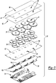
- the larger induction cooking apparatus 20 which includes the coil beam assembly 38, cooktop panel 40, controller 30, and temperature sensor assembly 22.
- Each of the induction coils 26 included on one of the coil beam assemblies 38 is mounted above and supported on a beam 42 that extends horizontally/laterally across a burner box 44 of the cooktop 24 between a first beam end 46 and a second beam end 48.
- the beam 42 may be made from a variety of different materials; however, the beam 42 is preferably made of a non-ferromagnetic material like aluminum, for example, such that the beam 42 is not influenced by the induction coils 26 that it supports.
- ferrite foils 50 may be positioned between each induction coil 26 and the beam 42 to direct the electromagnetic field up towards the cooking region 28.
- the coil beam assemblies 38 extend in complementary parallel groups beneath the cooktop panel 40.
- the cooktop panel 40 may be made of glass or a glass-ceramic material and includes an upper surface 58 and a lower surface 60.
- a mica sheet 62 may be provided between the lower surface 60 of the cooktop panel 40 and the induction coils 26 to provide insulation.
- the upper surface 58 of the cooktop panel 40 is configured to support cookware 36 of various shapes and sizes and therefore acts as the cooking surface.
- the induction coils 26, together with the ferrite foils 50 concentrate a field of electromagnetic flux above the upper surface 58 of the cooktop panel 40 in the cooking region(s) 28.
- the controller 30 is positioned beneath the coil beam assembly 38.
- the controller 30 includes a first circuit board 64 that is electrically connected to the induction coils 26 in the coil beam assembly 38.
- the first circuit board 64 may be a printed circuit board (PCB) that includes the first electrical circuit 34, which is printed as conductive traces on a first substrate 66 that forms the first circuit board 64.
- PCB printed circuit board
- some materials that may be utilized for the first substrate 66 include, but are not limited to: FR-1, FR-4, FR-5, G-10, and G-11.
- the first electrical circuit 34 of the controller 30 is configured to generate one or more high frequency switching signals.
- the switching signals cause the induction coils 26 to generate the electromagnetic field in cookware 36 placed on the upper surface 58 of the cooktop panel 40.
- the controller 30 may also be referred to as an inverter or an induction power converter.
- the first electrical circuit 34 includes a plurality of conductive connections and is configured to communicate control signals and/or driving current to the induction coils 26.
- the conductive connections of the first electrical circuit 34 are arranged in electrical communication with the induction coils 26 via one or more electrical connectors 68 that are electrically connected to copper windings 70 forming the induction coils 26.
- the electrical connectors 68 may correspond to lead wires (as illustrated) or fast-connect terminals (e.g., "faston” connectors). If the latter option is utilized, the conductive connections of the first electrical circuit 34 may be configured as female terminals and the electrical connectors 68 on the induction coils 26 may be configured as male terminals or vice versa to establish an electrical connection between the first electrical circuit 34 and the induction coils 26.
- the copper windings 70 of the induction coils 26 may be wound on coil formers 72.
- Each coil formers 72 may be, for example, a plastic bobbin or housing.
- the copper windings 70 of each induction coil 26 may be wound on one coil former 72.
- the first electrical circuit 34 may extend along a length of the beam 42 such that the conductive contacts of the first electrical circuit 34 are aligned with the electrical connectors 68 on each induction coil 26.
- the induction coils 26 in each coil beam assembly 38 may share a single electrical circuit 34.
- the coil beam assemblies 38 are positioned over the first circuit board 64 with the electrical connectors 68 of the induction coils 26 aligned with the corresponding conductive contacts of the first electrical circuit 34. Then the coil beam assemblies 38 are lowered such that electrical connectors 68 of the induction coils 26 engage the corresponding conductive contacts of the first electrical circuit 34.
- the controller 30, including the first circuit board 64 may be mounted to and supported by the bottom wall 52 of the burner box 44 or positioned in a plastic support tray. As previously discussed, the beam 42 is mounted in the burner box 44 at a position that is spaced above the first circuit board 64.
- the temperature sensor 80 and the guiding support 82 are arranged in a clearance fit with one another and the opening 78 such that both the temperature sensor 80 and the guiding support 82 are free to move, slide, and tilt within the opening 78 in the induction coil 26. It should also be appreciated that both the beam 42 and the mica sheet 62 have apertures 84, 85 that are aligned with the openings 78 in the induction coils 26 through which the temperature sensor 80 may extend.
- the temperature sensor 80 extends axially along a temperature sensor axis 86 between an upper end 88 and a lower end 90.
- the upper end 88 of the temperature sensor 80 sits above the top surface 74 of the induction coil 26 and the lower end 90 of the temperature sensor 80 includes one or more wires 92.
- each wire 92 may be encased in an insulator sleeve 94 along part of their length.
- the temperature sensors 80 may correspond to negative temperature coefficient (NTC) sensors configured to adjust a resistance based on a temperature proximate to each temperature sensor 80.
- NTC negative temperature coefficient
- each temperature sensor 80 may include a thermistor 96 and a sensor enclosure 98 that surrounds at least a portion of the thermistor 96.
- the sensor enclosure 98 protects the thermistor 96 and may optionally act as an electrical insulator.
- the temperature sensors 80 communicate temperature signals for the induction coils 26. These temperature signals are utilized for temperature control and regulation purposes.
- the second circuit board 100 includes a second substrate 108 and a second electrical circuit 110 that is disposed on the second substrate 108.
- the second circuit board 100 may be a printed circuit board (PCB), where the second electrical circuit 110 is formed by conductive traces that are printed on the second substrate 108 of the second circuit board 100.
- the one or more wires 92 of the temperature sensor 80 are electrically connected to the second electrical circuit 110.
- the wires 92 of the temperature sensor 80 may be soldered to the conductive traces forming the second electrical circuit 110.
- the second electrical circuit 110 receives the temperature signals from the temperature sensor(s) 80.
- the second electrical circuit 110 may be configured to process the temperature signals itself or may simply be configured to transmit the temperature signals to the controller 30.
- the induction cooking apparatus 20 may include an electronic interface between the first circuit board 64 and the second circuit board 100 that is configured to pass signals (e.g. temperature signals) from the second circuit board 100 to the first circuit board 64.
- the second circuit board 100 includes one or more cantilevered leaf-spring structures 112 that support the temperature sensors 80.
- Each cantilevered leaf-spring structure 112 is integral with the second substrate 108 and is formed by a U-shaped slot 114 that extends through the second circuit board 100.
- the cantilevered leaf-spring structure 112 therefore operates as a living hinge.
- the cantilevered leaf-spring structure 112 includes a cantilever arm 116 that extends to a cantilever end 118, which is a free or terminal end that is not connected to the second circuit board 100 except through the cantilever arm 116.
- FIGs 6A and 6B illustrate the cantilevered leaf-spring structure 112 in its natural state before deflection, such as prior to installation of the cooktop panel 40 over the burner box 44.
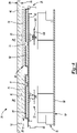
- FIGs 7A and 7B after the cooktop panel 40 is installed over the burner box 44, the lower surface 60 of the cooktop panel 40 and the second circuit board 100 are vertically spaced by a predetermined distance 122 that is less than a mounting height 124 of the temperature sensor 80.
- the cantilevered leaf-spring structure 112 is downwardly flexed and applies a biasing force 126 to the temperature sensor 80 that is directed upwards towards the cooktop panel 40.
- the second circuit board 100 for the temperature sensors 80 By including a second circuit board 100 for the temperature sensors 80, which is separate and distinct from the first circuit board 64 powering the induction coils 26, packaging constraints are avoided. For example, space on the first circuit board 64 is crowded by numerous electronic components, making it difficult to find room for the U-shaped slot 114 and cantilevered leaf-spring structure 112 that is connected to each temperature sensor 80. By providing a second circuit board 100 for the temperature sensors 80, sufficient room is created for the cantilevered leaf-spring structures 112. In addition, the thickness and material composition of the second circuit board 100 can be selected to specifically provide the desired mechanical properties of the cantilevered leaf-spring structure(s) 112.
- the top end 146 of the guiding support 82 is disposed in contact with the flange 136 of the temperature sensor 80 and the bottom end 148 of the guiding support 82 is disposed in contact with the cantilever end 118 such that the biasing force 126 that the cantilevered leaf-spring structure 112 provides when flexed is transmitted through the guiding support 82 to the flange 136 at the upper end 88 of the temperature sensor 80.
- the top end 146 of guiding support 82 includes an end face 154 that is bounded by an inner circumferential edge 156 and an outer circumferential edge 158.
- the guiding support 82 is free to slide, tilt, and gimbal relative to both the temperature sensor 80 and the cantilevered leaf-spring structure 112 while remaining a load bearing structure that transmits the biasing force 126 created by the deflection of the cantilevered leaf-spring structure 112 to the flange 136 at the upper end 88 of the temperature sensor 80.
- the guiding support 82 can move and tilt independently of the temperature sensor 80 and the cantilevered leaf-spring structure 112.
- this takes the load off the temperature sensor 80 and specifically the connection between the wires 92 at the lower end 90 of the temperature sensor 80 and the cantilever end 118.
- connection between the wires 92 at the lower end 90 of the temperature sensor 80 and the cantilever end 118 may be, for example, a soldered connection, which can fail under load.
- the guiding support 82 takes the load of the wires 92 and this connection and therefore provides greater durability.
Landscapes
- Physics & Mathematics (AREA)
- Electromagnetism (AREA)
- General Physics & Mathematics (AREA)
- Nonlinear Science (AREA)
- Induction Heating Cooking Devices (AREA)
Applications Claiming Priority (1)
| Application Number | Priority Date | Filing Date | Title |
|---|---|---|---|
| IN202011041810 | 2020-09-25 |
Publications (1)
| Publication Number | Publication Date |
|---|---|
| EP3975663A1 true EP3975663A1 (fr) | 2022-03-30 |
Family
ID=77913048
Family Applications (1)
| Application Number | Title | Priority Date | Filing Date |
|---|---|---|---|
| EP21198697.1A Withdrawn EP3975663A1 (fr) | 2020-09-25 | 2021-09-23 | Ensemble capteur de température pour plaque de cuisson à induction |
Country Status (2)
| Country | Link |
|---|---|
| US (1) | US20220104315A1 (fr) |
| EP (1) | EP3975663A1 (fr) |
Families Citing this family (2)
| Publication number | Priority date | Publication date | Assignee | Title |
|---|---|---|---|---|
| US20240344708A1 (en) * | 2023-04-14 | 2024-10-17 | Haier Us Appliance Solutions, Inc. | Removable control system for a heating coil or cooktop |
| US20250334272A1 (en) * | 2024-04-25 | 2025-10-30 | Whirlpool Corporation | Spring based temperature sensor holders for a cooktop |
Citations (3)
| Publication number | Priority date | Publication date | Assignee | Title |
|---|---|---|---|---|
| JP2013084372A (ja) * | 2011-10-06 | 2013-05-09 | Daihen Corp | 電磁誘導加熱調理器 |
| US20150341990A1 (en) * | 2012-10-22 | 2015-11-26 | Panasonic Corporation | Induction heating cooker |
| EP3544377A1 (fr) * | 2018-03-23 | 2019-09-25 | Whirlpool Corporation | Caractéristiques de compression de capteur de température pour ensemble de plaque de cuisson à induction |
-
2020
- 2020-11-05 US US17/089,878 patent/US20220104315A1/en not_active Abandoned
-
2021
- 2021-09-23 EP EP21198697.1A patent/EP3975663A1/fr not_active Withdrawn
Patent Citations (3)
| Publication number | Priority date | Publication date | Assignee | Title |
|---|---|---|---|---|
| JP2013084372A (ja) * | 2011-10-06 | 2013-05-09 | Daihen Corp | 電磁誘導加熱調理器 |
| US20150341990A1 (en) * | 2012-10-22 | 2015-11-26 | Panasonic Corporation | Induction heating cooker |
| EP3544377A1 (fr) * | 2018-03-23 | 2019-09-25 | Whirlpool Corporation | Caractéristiques de compression de capteur de température pour ensemble de plaque de cuisson à induction |
Also Published As
| Publication number | Publication date |
|---|---|
| US20220104315A1 (en) | 2022-03-31 |
Similar Documents
| Publication | Publication Date | Title |
|---|---|---|
| US20250344295A1 (en) | Induction coil compression apparatus for beam assembly | |
| EP3651550B1 (fr) | Dispositif de chauffage par induction possédant une structure de refroidissement améliorée | |
| US11405989B2 (en) | Temperature sensor compression features for induction cooktop assembly | |
| US11310874B2 (en) | Induction cooktop with improved magnetic flux concentrating foil | |
| US7786414B2 (en) | Induction heating device and hob having such an induction heating device | |
| WO2014056785A1 (fr) | Appareil de cuisson sans fil fonctionnant sur une table de cuisson à chauffage par induction | |
| US11388785B2 (en) | Connection interface for induction coil array | |
| EP3996470B1 (fr) | Appareil de cuisson à induction comportant un dissipateur thermique | |
| KR20110040120A (ko) | 조리기기용 가열장치와 그 제조방법 및 조리기기 | |
| EP3975663A1 (fr) | Ensemble capteur de température pour plaque de cuisson à induction | |
| CN114251689A (zh) | 用于感应式炉灶的温度传感器组件 | |
| EP4007450B1 (fr) | Cuisinière électrique | |
| US11284480B2 (en) | Sensor holding tray fixing | |
| JP4086285B2 (ja) | 誘導加熱調理器 | |
| US20210071873A1 (en) | Embossed feature for cooktop assembly | |
| CN217546343U (zh) | 一种电磁加热单元以及电磁烹饪器具 | |
| CN215777227U (zh) | 电磁加热锅具组件 | |
| JP4843460B2 (ja) | 誘導加熱調理器 | |
| EP3448120B1 (fr) | Plaque de cuisson | |
| JP2025001890A (ja) | 誘導加熱調理器 | |
| KR20250043242A (ko) | 조리기기 | |
| KR20220060669A (ko) | 전기 레인지 | |
| KR20190096028A (ko) | 조리기기 |
Legal Events
| Date | Code | Title | Description |
|---|---|---|---|
| PUAI | Public reference made under article 153(3) epc to a published international application that has entered the european phase |
Free format text: ORIGINAL CODE: 0009012 |
|
| STAA | Information on the status of an ep patent application or granted ep patent |
Free format text: STATUS: THE APPLICATION HAS BEEN PUBLISHED |
|
| AK | Designated contracting states |
Kind code of ref document: A1 Designated state(s): AL AT BE BG CH CY CZ DE DK EE ES FI FR GB GR HR HU IE IS IT LI LT LU LV MC MK MT NL NO PL PT RO RS SE SI SK SM TR |
|
| STAA | Information on the status of an ep patent application or granted ep patent |
Free format text: STATUS: THE APPLICATION IS DEEMED TO BE WITHDRAWN |
|
| 18D | Application deemed to be withdrawn |
Effective date: 20221001 |