EP3975794B1 - Ensemble de sangles convertible de sac de golf - Google Patents
Ensemble de sangles convertible de sac de golf Download PDFInfo
- Publication number
- EP3975794B1 EP3975794B1 EP20814157.2A EP20814157A EP3975794B1 EP 3975794 B1 EP3975794 B1 EP 3975794B1 EP 20814157 A EP20814157 A EP 20814157A EP 3975794 B1 EP3975794 B1 EP 3975794B1
- Authority
- EP
- European Patent Office
- Prior art keywords
- strap
- puck
- side opening
- slit
- opening
- Prior art date
- Legal status (The legal status is an assumption and is not a legal conclusion. Google has not performed a legal analysis and makes no representation as to the accuracy of the status listed.)
- Active
Links
Images


Classifications
-
- A—HUMAN NECESSITIES
- A45—HAND OR TRAVELLING ARTICLES
- A45C—PURSES; LUGGAGE; HAND CARRIED BAGS
- A45C13/00—Details; Accessories
- A45C13/30—Straps; Bands
-
- A—HUMAN NECESSITIES
- A45—HAND OR TRAVELLING ARTICLES
- A45F—TRAVELLING OR CAMP EQUIPMENT: SACKS OR PACKS CARRIED ON THE BODY
- A45F3/00—Travelling or camp articles; Sacks or packs carried on the body
- A45F3/02—Sacks or packs carried on the body by means of one strap passing over the shoulder
-
- A—HUMAN NECESSITIES
- A45—HAND OR TRAVELLING ARTICLES
- A45F—TRAVELLING OR CAMP EQUIPMENT: SACKS OR PACKS CARRIED ON THE BODY
- A45F3/00—Travelling or camp articles; Sacks or packs carried on the body
- A45F3/04—Sacks or packs carried on the body by means of two straps passing over the two shoulders
-
- A—HUMAN NECESSITIES
- A45—HAND OR TRAVELLING ARTICLES
- A45F—TRAVELLING OR CAMP EQUIPMENT: SACKS OR PACKS CARRIED ON THE BODY
- A45F3/00—Travelling or camp articles; Sacks or packs carried on the body
- A45F3/04—Sacks or packs carried on the body by means of two straps passing over the two shoulders
- A45F3/047—Sacks or packs carried on the body by means of two straps passing over the two shoulders with adjustable fastenings for the shoulder straps or waist belts
-
- A—HUMAN NECESSITIES
- A45—HAND OR TRAVELLING ARTICLES
- A45F—TRAVELLING OR CAMP EQUIPMENT: SACKS OR PACKS CARRIED ON THE BODY
- A45F3/00—Travelling or camp articles; Sacks or packs carried on the body
- A45F3/14—Carrying-straps; Pack-carrying harnesses
-
- A—HUMAN NECESSITIES
- A63—SPORTS; GAMES; AMUSEMENTS
- A63B—APPARATUS FOR PHYSICAL TRAINING, GYMNASTICS, SWIMMING, CLIMBING, OR FENCING; BALL GAMES; TRAINING EQUIPMENT
- A63B55/00—Bags for golf clubs; Stands for golf clubs for use on the course; Wheeled carriers specially adapted for golf bags
- A63B55/408—Releasably mounted accessories fitted outside the bag, e.g. straps or holders
-
- A—HUMAN NECESSITIES
- A44—HABERDASHERY; JEWELLERY
- A44B—BUTTONS, PINS, BUCKLES, SLIDE FASTENERS, OR THE LIKE
- A44B11/00—Buckles; Similar fasteners for interconnecting straps or the like, e.g. for safety belts
- A44B11/02—Buckles; Similar fasteners for interconnecting straps or the like, e.g. for safety belts frictionally engaging surface of straps
-
- A—HUMAN NECESSITIES
- A45—HAND OR TRAVELLING ARTICLES
- A45C—PURSES; LUGGAGE; HAND CARRIED BAGS
- A45C3/00—Flexible luggage; Handbags
- A45C2003/007—Sport bags
-
- A—HUMAN NECESSITIES
- A45—HAND OR TRAVELLING ARTICLES
- A45F—TRAVELLING OR CAMP EQUIPMENT: SACKS OR PACKS CARRIED ON THE BODY
- A45F3/00—Travelling or camp articles; Sacks or packs carried on the body
- A45F2003/001—Accessories
-
- A—HUMAN NECESSITIES
- A45—HAND OR TRAVELLING ARTICLES
- A45F—TRAVELLING OR CAMP EQUIPMENT: SACKS OR PACKS CARRIED ON THE BODY
- A45F4/00—Travelling or camp articles which may be converted into other articles or into objects for other use; Sacks or packs carried on the body and convertible into other articles or into objects for other use
- A45F4/02—Sacks or packs convertible into other articles or into objects for other use
- A45F2004/023—Sacks or packs convertible into other articles or into objects for other use into articles covered by groups A45F3/00 - A45F3/15
-
- A—HUMAN NECESSITIES
- A45—HAND OR TRAVELLING ARTICLES
- A45F—TRAVELLING OR CAMP EQUIPMENT: SACKS OR PACKS CARRIED ON THE BODY
- A45F5/00—Holders or carriers for hand articles; Holders or carriers for use while travelling or camping
- A45F2005/002—Holders or carriers for hand articles; Holders or carriers for use while travelling or camping combined with other objects
-
- A—HUMAN NECESSITIES
- A45—HAND OR TRAVELLING ARTICLES
- A45F—TRAVELLING OR CAMP EQUIPMENT: SACKS OR PACKS CARRIED ON THE BODY
- A45F5/00—Holders or carriers for hand articles; Holders or carriers for use while travelling or camping
-
- A—HUMAN NECESSITIES
- A63—SPORTS; GAMES; AMUSEMENTS
- A63B—APPARATUS FOR PHYSICAL TRAINING, GYMNASTICS, SWIMMING, CLIMBING, OR FENCING; BALL GAMES; TRAINING EQUIPMENT
- A63B55/00—Bags for golf clubs; Stands for golf clubs for use on the course; Wheeled carriers specially adapted for golf bags
Definitions
- Carry bags generally comprise a strap system that allows the user carry the weight of the bag on their shoulders.
- the strap system is a single strap system that allows the user to carry the bag on one side of their body.
- the strap system is a double-strap system that allows the user to wear the bag like a backpack.
- the double-strap systems often have crisscrossing straps that are worn like a backpack.
- the bag can be lifted by one strap and carried at the right side of the user's body.
- the orientation of the double-strap designs prevents the user from conveniently using a single strap on the left side of the user's body.
- the strap is not configured to distribute the weight of the bag accurately when the bag is carried on the left side of the user's body.
- double-strap systems do not function well for single strap carrying because the straps are fixed to each other at a crisscrossing intersection. The intersection can run into the user's elbow when the user is picking up the bag by a single strap.
- TWM300990U discloses a buckle for a rucksack.
- US6152342 discloses a golf bag with a double strap and buckle.
- the second section 106 comprises a second end and a second attachment end 112.
- the second end is coupled to the golf bag.
- the second attachment end 112 can be coupled to the back puck 100.
- the second attachment end 112 is permanently coupled, attached, sewn onto the back puck 100, and/or removably attached with snap-fit or other detachable coupling mechanisms.
- the second end can be coupled to the back of the golf bag, offset towards a left side of the golf bag.
- the first and second ends of the first strap 102 can be configured to be removable from the golf bag.
- the first strap 102 further comprises a padded portion.
- the discontinuity of the first strap 102 prevents the first strap 102 from rubbing against and creating friction with the second strap 108.
- the second strap 108 can slide freely through the back puck 100, without being hindered by the crossing of the first strap 102, which is attached to edges of the back puck 100.
- the first strap 102 can be continuous, so long as the second strap 108 is positioned below the first strap 102 in a channel, so that the second strap 108 does not contact the first strap 102.
- the second strap 108 can be continuous.
- the second strap 108 can comprise a first end and a second end.
- the first and second ends are coupled to the golf bag.
- the first end of the second strap 108 can be coupled to the back of the golf bag, offset towards the left side of the golf bag.
- the second end of the second strap 108 can be coupled to the back of the golf bag, offset towards the right side of the golf bag.
- the first and second ends of the second strap 108 can be configured to be removable from the golf bag.
- the second strap 108 further comprises a padded portion.
- the first and second straps 102, 108 comprise a strap width 180 and a strap thickness 182.
- the back puck 100 can configure the first and second straps 102, 108.
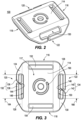
- the back puck 100 comprises a central body 114, a first side 120, a second side 122, a front, and a rear.
- the central body 114 comprises a top 116 and a bottom 118.
- the top 116 comprises a first attachment opening 152 for receiving the first attachment end 110 of the first strap 102.
- the first attachment opening 152 can be cut from the central body 114 such that a plane extending through the first attachment opening 152 can be orthogonal to a plane extending through the central body 114.
- the bottom 118 comprises a second attachment opening 154 for receiving the second attachment end 112 of the first strap 102.
- the second attachment opening 154 can be cut from the central body 114 such that a plane extending through the second attachment opening 154 can be orthogonal to a plane extending through the central body 114.
- the first and/or second attachment end 112 of the first strap 102 can be looped through the first and/or second attachment opening 154 and secured back onto the first strap 102 by stitching.
- the central body 114 of the back puck 100 can comprise a logo or emblem 190.
- the logo or emblem 190 can be embossed, printed, or cut through the central body 114. In the illustrated embodiment, the logo 190 is cut through the central body 114.
- the first and second sides 120, 122 of the back puck 100 can be configured to removably receive the second strap 108.
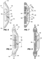
- the first side 120 and the second side 122 can be angled downward from the central body 114 towards the rear of the puck.
- the first and second side 122 can be angled downward from the central body 114 at equal angles.
- the first side 120 can be angled downward from the central body 114 at a first side angle 160 between 10 and 90 degrees.
- the second side 122 can be angled downward from the central body 114 at a second side angle 160 between 10 degrees and 90 degrees.
- the first side angle 160 and/or the second side angle 162 can be between 10 and 20 degrees, 20 and 30 degrees, 30 and 40 degrees, 40 and 50 degrees, 50 and 60 degrees, 60 and 70 degrees, 70 and 80 degrees, 80 and 90 degrees.
- the first side 120 can comprise a first top corner 124, a first bottom corner 126, and a first arm 132.
- the first arm 132 comprises a top first arm portion 136 and a bottom first arm portion 138.
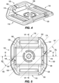
- the first arm 132 is discontinuous such that the space between the top first arm portion 136 and the bottom first arm portion 138 defines a first slit 144.
- the top first arm portion 136 can connect to and extend from the first top corner 124.
- the bottom first arm portion 138 can connect to and extend from the first bottom corner 138.
- the second side 122 can comprise a second top corner 128, a second bottom corner 130, and a second arm 134.
- the second arm 134 comprises a top second arm portion 140 and a bottom second arm portion 142.
- the second arm 134 is discontinuous such that the space between the top second arm portion 140 and the bottom second arm portion 142 defines a second slit 146.
- the top second arm portion 140 can connect to and extend from the second top corner 128.
- the bottom second arm portion 142 can connect to and extend from the second bottom corner 130.
- the first slit 144 and the second slit 146 allow the second strap to be engaged or disengaged from the back puck 100.
- the first and second slits 144, 146 in the first and second arms 132, 134, respectively, allow the strap system to convert between the single-strap configuration and the double-strap configuration.
- the first side 120 defines a first side opening 148, configured to receive the second strap 108.
- the first top corner 124, the first bottom corner 126, the first arm 132, and the central body 114 of the back puck 100 can form boundaries for the first side opening 148.
- the first arm 132 defines an edge of the first side opening 148.
- the first slit 144 can open into the first side opening 148.
- the second side 122 defines a second side opening 150, configured to receive the second strap 108.
- the second top corner 128, the second bottom corner 130, the second arm 134, and the central body 114 can form boundaries for the second side opening 150.
- the second arm 134 defines an edge of the second side opening 150, and the second slit 146 can open into the second side opening 150.
- the first side opening 148 comprises a first side opening width 164 and a first side opening height 168.
- the second side opening 150 comprises a second side opening width 166 and a second side opening height 170.
- the first side opening width 164 and the second side opening width 166 may be the same width.
- the first side opening height 168 and the second side opening height 170 may be the same height.
- the first side opening width 164 and second side opening width 166 are in a range of 20 mm to 30 mm.
- the first side opening width 164 and second side opening width 166 can be between 20 mm and 22 mm, 22 mm and 24 mm, 24 mm and 26 mm, 26 mm and 28 mm, or 28 mm and 30 mm.
- the first and/or second side opening widths 164, 166 can be 20 mm, 21 mm, 22 mm, 23 mm, 24 mm, 25 mm, 26 mm, 27 mm, 28 mm, 29 mm, or 30 mm.
- the first side opening width 164 and second side opening width 166 are greater than the second strap width 180.
- the first side opening height 168 and the second side opening height 170 are in a range of 2 mm to 8 mm.
- the first side opening height 168 and the second side opening height 170 can be between 2 mm and 3 mm, 3 mm and 4 mm, 4 mm and 5 mm, 5 mm and 6 mm, 6 mm and 7 mm, or 7 mm and 8 mm.
- the first and/or second side opening heights 168, 170 can be 2 mm, 3 mm, 4 mm, 5 mm, 6 mm, 7 mm, or 8 mm.
- the first side opening 148 and the second side opening 150 are sized to receive the second strap 108.
- the first and second side opening widths 164, 166 are greater than the second strap width 180.
- the first and second side opening heights 168, 170 are greater than the second side strap thickness 182.
- the first and second side opening widths 164, 166 and heights 168, 170 allow the second strap 108 to fit comfortably within and slide freely through the first and second side openings 148, 150.
- the first slit 144 and the second slit 146 comprise a slit width 172.
- the slit width 172 can be measured perpendicularly from a plane tangent to an end of the top arm portion 136 or 140 to a plane tangent to an end of the bottom arm portion 138 or 142, respectively.
- the slit width 172 is in a range of 0.5 mm to 5 mm.
- the slit width 172 can be between 0.5 mm and 0.7 mm, 0.7 mm and 0.9 mm, 0.9 mm and 1.1 mm, 1 mm and 1.5 mm, 1.5 mm and 2 mm, 2 mm and 3 mm, 3 mm and 4 mm, or 4 mm and 5 mm. In some embodiments, the slit width 172 can be 0.5 mm, 0.6 mm, 0.7 mm, 0.8 mm, 0.9 mm, or 1.0 mm. The slit width 172 is greater than the second strap thickness 182. The first slit 144 and second slit 146 allow for insertion and removal of the second strap 108 from the first side opening 148 and the second side opening 150, respectively.
- the first slit 144 can be closer to the top 116 than the bottom 118 of the back puck 100, and the second slit 146 can be closer to the bottom 118 than the top 116 of the back puck 100.
- the top first arm portion 136 can be shorter than the bottom first arm portion 138.
- the top second arm portion 140 can be longer than the bottom second arm portion 142.
- the position of the first slit 144 and the second slit 146 as defined by the lengths of the arm portions affects the ability of the back puck 100 to retain the second strap 108 without it slipping out when the golf bag is in the double-strap configuration.
- the material of the second strap 108 can constrict within the first side opening 148 and the second side opening 150.
- the second strap 108 can constrict towards the first top corner 124 at the top 116 of the puck 100.
- the location of the first slit 144 closer to the top 116 (and the first top corner 124) than the bottom 118 (and the first bottom corner 126) can prevent an edge of the second strap 108 from slipping out when the strap 108 is bunched up.
- the second strap 108 can constrict towards the second bottom corner 130 at the bottom 118 of the puck 100.
- the location of the second slit 146 closer to the bottom 118 (and the second bottom corner 130) than the top 116 (and the second top corner 128) can prevent an edge of the second strap 108 from slipping out when the strap 108 is bunched up. Therefore, the lengths of the top first arm portion 136, bottom first arm portion 138, top second arm portion 140, and bottom second arm portion 142 can prevent the second strap 108 from slipping out through the first and second slits 144, 146. This security helps loosely retain the second strap 108 within the back puck, so that the second strap 108 is slidably connected to the first strap 102.
- the first and/or second slit 144, 146 can be angled with respect to the first and/or second arm 132, 134, respectively. In some embodiments, the first and/or second slit 144, 146 can be angled roughly parallel to a reference line 174 drawn from the first top corner 124 of the puck 100 to the second bottom corner 130 of the puck 100. In some embodiments, the first and/or second slit 144, 146 can comprise any angle suitable for insertion and removal of the second strap 108. In some embodiments, a longitudinal axis 178 is defined in a direction from the first side 120 to the second side 122, and centered between the top 116 and bottom 118 of the back puck, as taken from the rear view.
- a first slit reference line 145 runs parallel through the first slit, as taken from the rear view.
- a second slit reference line 147 runs parallel through the second slit, as taken from the rear view.
- the first slit 144 is angled at a first slit angle ⁇ 1 , which is measured counterclockwise from the longitudinal axis 178 to the first slit reference line 145.
- the second slit 146 is angled at a second slit angle ⁇ 2 , which is measured counterclockwise from the longitudinal axis 178 to the second slit reference line 147.
- the first slit angle ⁇ 1 can be equal to the second slit angle ⁇ 2 .
- the first slit angle ⁇ 1 and/or the second slit angle ⁇ 2 have a value of between 0 and 80 degrees. In some embodiments, the first slit angle ⁇ 1 and/or the second slit angle ⁇ 2 is between 0 and 10 degrees, 10 and 20 degrees, 20 and 30 degrees, 30 and 40 degrees, 40 and 50 degrees, 50 and 60 degrees, 60 and 70 degrees, or 70 and 80 degrees.
- the angulation of the first and second slits 144 and 146 helps prevent the second strap from inadvertently falling out of the back puck (exiting the first and/or second slit 144, 146) in the double-strap configuration, while also allowing the second strap to be quickly removed to convert the strap system to the single-strap configuration.
- the design of the first and second slits 144, 146 allows quick and versatile conversion and configuration of the strap system.
- the first side opening 148 and the second side opening 150 can be configured to removably receive the second strap 108 of the golf bag.
- a linear pathway 158 extends through the first side 120 opening and the second side opening 150.
- the linear pathway comprises the space directly between the first side opening 148 and the second side opening 150. No part of the back puck 100 intersects the linear pathway.
- the pathway comprises a pathway width having the same width as the first side opening width 164 and second side opening width 166.
- a channel 156 cuts into the central body 114.
- the channel 156 runs parallel to the linear pathway 158.
- the linear pathway 158 runs through the channel 156.
- the channel 156 extends from the first side opening 148 to the second side opening 150.
- the channel 156 can be as wide as the first side opening 148 and the second side opening 150.
- the channel 156 can be cut or recessed into the face of the central body 114, such that the plane of the channel 156 is parallel to the plane of the central body 114.
- the channel 156 can have a certain depth 176. The depth 176 of the channel 156 can be less than the thickness of the central body 114.
- the channel depth 176 can be between 0 mm and 3 mm. In some embodiments, the channel depth 176 can be between 0 mm and 0.5 mm, 0.5 mm and 1 mm, 1 mm and 1.5 mm, 1.5 mm and 2 mm, 2 mm and 2.5 mm, or 2.5 mm and 3 mm.
- the first side 120 opening, second side opening 150, and the channel 156 of the back puck 100 are configured to allow free movement of the second strap 108 along the linear pathway 158.
- the first strap 102 is independent from the second strap 108.
- the second strap 108 is disengaged from the back puck 100.
- the back puck 100 can be held and fixed between the first and second sections 104, 106 of the first strap 102.
- the second strap 108 is engaged with the back puck 100.
- the second strap 108 can run along the channel 156 and/or the linear pathway 158 cut through the central body 114 and bounded by the first side opening 148 and second side opening 150 of the back puck 100.
- the second strap 108 is configured to slide along the channel 156 having no bends, folds, or turns, and without resistance or clamping such that the second strap 108 is not fixed in position to the back puck 100 along the linear pathway 158 between first side opening 148 and the second side opening 150.
- the sliding movement of the second strap 108 allows the weight of the golf bag to be automatically distributed (self-adjusted) between both the first and second straps 102, 108 without the user adjusting the length of either strap.
- the back puck 100 restricts the second strap 108 to some degree in every direction other than the direction of the channel 156.
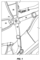
- the back puck 100 keeps the straps oriented in a configuration that (1) can be worn over both shoulders and (2) evenly distributes the weight of the golf bag.
- the first strap 102 and the second strap 108 can be oriented perpendicular to one another by the back puck 100.
- This crisscrossing setup of the first strap 102 and the second strap 108, connected by the back puck 100, allows the user to not only easily position the golf bag on his or her back, but also allows the user to walk and move without tangling or shifting the straps 102, 108 into an undesirable position.
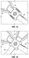
- the strap assembly can be used in a single-strap configuration, such as is illustrated in FIG. 14 , or in a double strap configuration, as illustrated in FIG. 15 .
- the second strap 108 is engaged with the back puck 100.
- engaging the second strap 108 with the back puck 100 comprises inserting an edge of the second strap 108 into the first slit 144 on the first side 120 of the back puck 100.
- the second strap 108 can be then fed fully through the first slit 144 into the first side opening 148, which requires some temporary bunching of the second strap 108 material.
- the second strap 108 can be then allowed to spread out into the first side opening 148, and the first arm 132 holds the second strap 108 within the first side opening 148.
- another portion of the second strap 108 can be inserted into the second slit 146 on the second side 122 of the back puck 100.
- the second strap 108 can be then fed fully through the second slit 146 and secured with the second side opening 150 in a manner similar to the insertion of the second strap 108 into the first side opening 148.
- the second arm 134 holds the second strap 108 within the second side opening 150.
- the second strap 108 Upon completion of the insertion of the second strap 108 into the first and second side openings 148, 150, the second strap 108 can lie along the linear pathway 158 and experiences no resistance to motion along the linear pathway 158.
- the second strap 108 can be disengaged by reversing the above insertion process.
- the second strap 108 can be pulled laterally through the first and/or second slit 144, 146 to remove the second strap from the first side opening 148 and/or the second side opening 150.
- the second strap 108 can be configured to be fully removable from the golf bag, allowing the user to configure the golf bag more permanently in a single-strap configuration. In these embodiments, the second strap 108 can be removed to simplify the bag, lighten the bag, and improve aesthetics.
- the convertible strap system can provide the user with more versatility in how he or she carries the golf bag.
- the convertible strap system can reduce fatigue from carrying the golf bag by allowing the user to adapt the strap system to the user's needs.
- the convertible strap system provides a solution for caddies who desire to carry a golf bag by placing a single strap of each bag on each shoulder.
- the convertible strap system is simple, requiring no tools for the conversion process between the single-strap and double-strap configuration.
- the method of engaging or disengaging the second strap 108 with the back puck 100 can be understood without detailed instructions. All these features make the convertible strap system an effective solution to the need in the art for a convertible strap system.
Landscapes
- Health & Medical Sciences (AREA)
- General Health & Medical Sciences (AREA)
- Physical Education & Sports Medicine (AREA)
- Purses, Travelling Bags, Baskets, Or Suitcases (AREA)
Claims (10)
- Système de sangles pour un sac de golf, comprenant :
une première sangle (102), comprenant :une première section (104) avec une première extrémité et une première extrémité de fixation (110), la première extrémité étant couplée au sac de golf ; etune seconde section (106) avec une seconde extrémité de fixation (112) et une seconde extrémité, la seconde extrémité étant couplée au sac de golf ;une seconde sangle (108) comprenant des première et seconde extrémités toutes deux couplées au sac de golf ;une rondelle dorsale (100), comprenant :une partie supérieure (116) comprenant une première ouverture de fixation (152) ;une partie inférieure (118) comprenant une seconde ouverture de fixation (154) ;dans lequel la première extrémité de fixation (110) de la première sangle (102) est couplée à la première ouverture de fixation (152) ; etla seconde extrémité de fixation (112) de la première sangle (102) est couplée à la seconde ouverture de fixation (154) ;caractérisé en ce que :la rondelle dorsale (100) comprend en outre un premier côté (120) comprenant un premier bras (132), et
un second côté (122) comprenant un second bras (134) ;dans lequel le premier bras (132) comprend une première partie de bras supérieure (136) et une première partie de bras inférieure (138), etle second bras (134) comprend une seconde partie de bras supérieure (140) et une seconde partie de bras inférieure (142),dans lequel le premier bras (132) définit une première fente (144) entre la première partie de bras supérieure (136) et la première partie de bras inférieure (138), etle second bras (134) définit une seconde fente (146) entre la seconde partie de bras supérieure (140) et la seconde partie de bras inférieure (142) ;dans lequel :le premier côté (120) et le second côté (122) sont inclinés à partir d'un reste de la rondelle dorsale (100) ;le premier côté (120) définit une première ouverture latérale (148), le premier bras (132) formant un bord de la première ouverture latérale (148) ;le second côté (122) définit une seconde ouverture latérale (150), le second bras (134) formant un bord de la seconde ouverture latérale (150) ;la seconde sangle (108) est configurée pour s'ajuster à l'intérieur de la première ouverture latérale (148) et de la seconde ouverture latérale (150) le long d'un trajet linéaire qui s'étend à travers la première ouverture latérale (148) et la seconde ouverture latérale (150) ;la seconde sangle (108) peut se déplacer librement le long du trajet linéaire ;le sac de golf peut être configuré pour être transporté dans une configuration à sangle unique ou dans une configuration à double sangle ;la seconde sangle (108) est libérée de la rondelle dorsale (100) dans la configuration à sangle unique ;la seconde sangle (108) est mise en prise avec la rondelle dorsale (100) dans la configuration à double sangle ;la seconde sangle (108) est mise en prise avec la rondelle dorsale (108) lorsque la seconde sangle (108) s'étend à travers la première ouverture latérale (148) et la seconde ouverture latérale (150) le long du trajet linéaire ; dans lequel :la rondelle dorsale (100) comprend en outre un corps central (114), un avant et un arrière opposés à l'avant ;un canal (156) s'étend de la première ouverture latérale (148) à la seconde ouverture latérale (150), parallèlement au trajet linéaire ;le canal (156) recoupe le corps central (114) le long de l'arrière de la rondelle dorsale (100) ;lorsqu'elle est dans la configuration à double sangle, la seconde sangle (108) est configurée pour coulisser le long du canal (156), ne présentant pas de courbes, de plis ou de tours, et sans résistance ni serrage, de sorte que la seconde sangle (108) n'est pas fixée en position à la rondelle dorsale (100) . - Système de sangles selon la revendication 1, dans lequel :la première extrémité de fixation (110) de la première sangle (102) est couplée de manière immobile à la première ouverture de fixation (152) ; etla seconde extrémité de fixation (112) de la première sangle (102) est couplée de manière immobile à la seconde ouverture de fixation (154).
- Système de sangles selon la revendication 1, dans lequel :la seconde ouverture latérale (150) présente une largeur de seconde ouverture latérale (166) ;la seconde sangle (108) présente une largeur de sangle (180) ; etla largeur de seconde ouverture latérale (166) est supérieure à la largeur de sangle (180).
- Système de sangles selon la revendication 1, dans lequel :la seconde ouverture latérale (150) présente une hauteur de seconde ouverture latérale (170) ;la seconde sangle (108) présente une épaisseur de sangle (182) ; etla hauteur de seconde ouverture latérale (170) est supérieure à l'épaisseur de sangle (182).
- Système de sangles selon la revendication 1, dans lequel :
le premier côté (120) et le second côté (122) de la rondelle dorsale (100) sont inclinés vers le bas à partir du corps central (114) vers l'arrière de la rondelle dorsale (100) . - Système de sangles selon la revendication 5, dans lequel :le premier côté (120) et le second côté (122) sont inclinés vers le bas à partir du corps central (114) à des angles égaux ;le premier côté (120) est incliné vers le bas selon un premier angle latéral (160), qui est mesuré à partir d'une vue de dessus entre le premier côté (120) et le corps central (114) ; etle second côté (122) est incliné vers le bas selon un second angle latéral (162), qui est mesuré à partir d'une vue de dessus entre le second côté (120) et le corps central (114) .
- Système de sangles selon la revendication 6, dans lequel le premier angle latéral (160) et le second angle latéral (162) présentent des valeurs comprises dans une plage d'angles sélectionnée dans le groupe comprenant : 10 et 20 degrés, 20 et 30 degrés, 30 et 40 degrés, 40 et 50 degrés, 50 et 60 degrés, 60 et 70 degrés, 70 et 80 degrés, et 80 et 90 degrés.
- Système de sangles selon la revendication 1, dans lequel la première fente (144) est plus proche de la partie supérieure (116) de la rondelle dorsale (100) que la seconde fente (146).
- Système de sangles selon la revendication 1, dans lequel :la seconde sangle (108) peut être retirée à travers la première fente (144) et la seconde fente (146) pour convertir le système de sangles de la configuration à double sangle à la configuration à sangle unique ; etla seconde sangle (108) peut être insérée à travers la première fente (144) et la seconde fente (146) pour convertir le système de sangles de la configuration à sangle unique à la configuration à double sangle.
- Système de sangles selon la revendication 1, dans lequel la seconde sangle (108) peut être retirée entièrement du sac de golf lorsque le système de sangles est dans la configuration à sangle unique.
Priority Applications (2)
| Application Number | Priority Date | Filing Date | Title |
|---|---|---|---|
| EP25150460.1A EP4512277A3 (fr) | 2019-05-31 | 2020-05-29 | Ensemble de sangles convertible de sac de golf |
| EP24193537.8A EP4434392A3 (fr) | 2019-05-31 | 2020-05-29 | Ensemble de sangles convertible de sac de golf |
Applications Claiming Priority (3)
| Application Number | Priority Date | Filing Date | Title |
|---|---|---|---|
| US201962855747P | 2019-05-31 | 2019-05-31 | |
| US202063001673P | 2020-03-30 | 2020-03-30 | |
| PCT/US2020/035400 WO2020243624A1 (fr) | 2019-05-31 | 2020-05-29 | Ensemble de sangles convertible de sac de golf |
Related Child Applications (3)
| Application Number | Title | Priority Date | Filing Date |
|---|---|---|---|
| EP24193537.8A Division-Into EP4434392A3 (fr) | 2019-05-31 | 2020-05-29 | Ensemble de sangles convertible de sac de golf |
| EP24193537.8A Division EP4434392A3 (fr) | 2019-05-31 | 2020-05-29 | Ensemble de sangles convertible de sac de golf |
| EP25150460.1A Division EP4512277A3 (fr) | 2019-05-31 | 2020-05-29 | Ensemble de sangles convertible de sac de golf |
Publications (3)
| Publication Number | Publication Date |
|---|---|
| EP3975794A1 EP3975794A1 (fr) | 2022-04-06 |
| EP3975794A4 EP3975794A4 (fr) | 2023-06-28 |
| EP3975794B1 true EP3975794B1 (fr) | 2024-10-09 |
Family
ID=73551196
Family Applications (3)
| Application Number | Title | Priority Date | Filing Date |
|---|---|---|---|
| EP24193537.8A Pending EP4434392A3 (fr) | 2019-05-31 | 2020-05-29 | Ensemble de sangles convertible de sac de golf |
| EP20814157.2A Active EP3975794B1 (fr) | 2019-05-31 | 2020-05-29 | Ensemble de sangles convertible de sac de golf |
| EP25150460.1A Pending EP4512277A3 (fr) | 2019-05-31 | 2020-05-29 | Ensemble de sangles convertible de sac de golf |
Family Applications Before (1)
| Application Number | Title | Priority Date | Filing Date |
|---|---|---|---|
| EP24193537.8A Pending EP4434392A3 (fr) | 2019-05-31 | 2020-05-29 | Ensemble de sangles convertible de sac de golf |
Family Applications After (1)
| Application Number | Title | Priority Date | Filing Date |
|---|---|---|---|
| EP25150460.1A Pending EP4512277A3 (fr) | 2019-05-31 | 2020-05-29 | Ensemble de sangles convertible de sac de golf |
Country Status (5)
| Country | Link |
|---|---|
| US (5) | US11192008B2 (fr) |
| EP (3) | EP4434392A3 (fr) |
| JP (3) | JP7569807B2 (fr) |
| KR (2) | KR102850927B1 (fr) |
| WO (1) | WO2020243624A1 (fr) |
Families Citing this family (9)
| Publication number | Priority date | Publication date | Assignee | Title |
|---|---|---|---|---|
| TWI544927B (zh) | 2008-03-17 | 2016-08-11 | 愛爾康研究有限公司 | 具有低濃度的表面活性劑以促進治療劑之生物可利用性的藥學組成物 |
| USD913843S1 (en) * | 2019-03-27 | 2021-03-23 | 5.11, Inc. | Strap anchor |
| EP4434392A3 (fr) * | 2019-05-31 | 2024-12-18 | Karsten Manufacturing Corporation | Ensemble de sangles convertible de sac de golf |
| US11944184B2 (en) * | 2020-06-10 | 2024-04-02 | Crosier Products, LLC | Systems and methods for attaching patches to equipment |
| US20220088447A1 (en) * | 2020-09-23 | 2022-03-24 | Kun-lin Shiao | Golf bag and fixing device for stand of the golf bag |
| CN121059005A (zh) | 2021-01-26 | 2025-12-05 | 明门瑞士股份有限公司 | 婴儿背带 |
| USD942841S1 (en) | 2021-08-11 | 2022-02-08 | Hoch Brands, LLC. | Securement device |
| US12594471B2 (en) | 2022-01-25 | 2026-04-07 | Frogger, LLC | Golf bags and similar having selectively movable straps |
| USD1114563S1 (en) | 2024-02-23 | 2026-02-24 | Yeti Coolers, Llc | Insulating container |
Family Cites Families (25)
| Publication number | Priority date | Publication date | Assignee | Title |
|---|---|---|---|---|
| US3739961A (en) * | 1971-02-18 | 1973-06-19 | J Soukeras | Safe personal effects pouches and strap means for under arm or shoulder wear |
| US4757927A (en) * | 1985-05-10 | 1988-07-19 | The Stanley Works | Holder for suspending rule clip or the like |
| US6131783A (en) | 1996-08-23 | 2000-10-17 | Maeng; Seop | Carrier belt for golf bag with adjustable shoulder loop |
| DE29615828U1 (de) * | 1996-09-11 | 1996-12-12 | creative pool trendscouting GmbH, 86391 Stadtbergen | Rucksack |
| US6152342A (en) * | 1998-07-20 | 2000-11-28 | Suk; Young J. | Golf bag with double strap and buckle |
| US6168060B1 (en) | 1998-09-16 | 2001-01-02 | Edward Mayers | Nested, two-layer golf bag strap for one-shoulder or two-shoulder carrying |
| US6006974A (en) | 1998-11-05 | 1999-12-28 | Morris Rosenbloom & Co., Inc. | Golf bag carrying straps |
| US6283350B1 (en) * | 2000-03-07 | 2001-09-04 | Mario Gottmeier | Backpack |
| US6457620B1 (en) | 2001-01-10 | 2002-10-01 | Ya Fang Tang | Golf bags and golf bag carrying systems |
| US6460747B1 (en) * | 2001-05-04 | 2002-10-08 | Karsten Manufacturing Corp. | Dual strap apparatus for golf bags |
| US6530129B1 (en) * | 2002-01-23 | 2003-03-11 | Ching-Feng Cheng | Golf bag carrying structure |
| JP2006334213A (ja) | 2005-06-03 | 2006-12-14 | Nifco Inc | リュックサック用バックル、および、リュックサック |
| USD591200S1 (en) * | 2008-03-10 | 2009-04-28 | James Marty Freeman | Strap end retainer with open slots |
| KR101016882B1 (ko) * | 2009-01-08 | 2011-02-22 | 백지숙 | 스트랩 조절구 |
| US20100293758A1 (en) | 2009-05-22 | 2010-11-25 | Shiao Kun-Lin | Auto-adjusting harness connector for shoulder straps of golf bag |
| US8322585B2 (en) | 2009-05-28 | 2012-12-04 | Nike, Inc. | Golf bag or other shoulder-borne device having double strap to single strap convertibility |
| US20120267410A1 (en) * | 2011-04-22 | 2012-10-25 | Loudenslager John H | Self-adjustable carrying strap system and methods to manufacture self-adjustable carrying strap system |
| US11771206B2 (en) * | 2011-04-22 | 2023-10-03 | Karsten Manufacturing Corporation | Self-adjustable carrying strap system and methods to manufacture self-adjustable carrying strap system |
| USD688977S1 (en) * | 2011-06-08 | 2013-09-03 | Paul Mohr | Locking four-tab |
| US8764360B2 (en) * | 2012-11-19 | 2014-07-01 | Southern Bracing Systems Enterprises, Llc | Strap connector |
| US10245486B2 (en) | 2016-03-18 | 2019-04-02 | Acushnet Company | Golf bag having hub shoulder strap connector for converting from two straps to single strap |
| US10449429B2 (en) | 2016-10-03 | 2019-10-22 | Karsten Manufacturing Corporation | Systems and methods for an adjustable strap system for a golf bag |
| US10548373B2 (en) * | 2017-03-07 | 2020-02-04 | Nite Ize, Inc. | Systems and methods for a side-loading strap buckle |
| US10610002B2 (en) | 2017-07-27 | 2020-04-07 | Parsons Xtreme Golf, LLC | Golf bag strap systems and methods to manufacture golf bag strap systems |
| EP4434392A3 (fr) * | 2019-05-31 | 2024-12-18 | Karsten Manufacturing Corporation | Ensemble de sangles convertible de sac de golf |
-
2020
- 2020-05-29 EP EP24193537.8A patent/EP4434392A3/fr active Pending
- 2020-05-29 KR KR1020217043318A patent/KR102850927B1/ko active Active
- 2020-05-29 US US16/888,338 patent/US11192008B2/en active Active
- 2020-05-29 EP EP20814157.2A patent/EP3975794B1/fr active Active
- 2020-05-29 WO PCT/US2020/035400 patent/WO2020243624A1/fr not_active Ceased
- 2020-05-29 JP JP2021570260A patent/JP7569807B2/ja active Active
- 2020-05-29 KR KR1020257027901A patent/KR20250133972A/ko active Pending
- 2020-05-29 EP EP25150460.1A patent/EP4512277A3/fr active Pending
-
2021
- 2021-12-07 US US17/643,092 patent/US11559728B2/en active Active
-
2022
- 2022-12-12 US US18/064,847 patent/US11857853B2/en active Active
-
2023
- 2023-12-18 US US18/544,192 patent/US12233320B2/en active Active
-
2024
- 2024-10-07 JP JP2024176011A patent/JP7823139B2/ja active Active
- 2024-10-07 JP JP2024176012A patent/JP7823140B2/ja active Active
-
2025
- 2025-02-25 US US19/063,041 patent/US20250195967A1/en active Pending
Also Published As
| Publication number | Publication date |
|---|---|
| US20200376354A1 (en) | 2020-12-03 |
| EP4512277A2 (fr) | 2025-02-26 |
| US20220096903A1 (en) | 2022-03-31 |
| JP7823139B2 (ja) | 2026-03-03 |
| US20240115915A1 (en) | 2024-04-11 |
| KR102850927B1 (ko) | 2025-08-26 |
| EP4434392A3 (fr) | 2024-12-18 |
| EP3975794A1 (fr) | 2022-04-06 |
| WO2020243624A1 (fr) | 2020-12-03 |
| JP2025011185A (ja) | 2025-01-23 |
| EP4434392A2 (fr) | 2024-09-25 |
| US11559728B2 (en) | 2023-01-24 |
| US12233320B2 (en) | 2025-02-25 |
| JP2022534246A (ja) | 2022-07-28 |
| US11192008B2 (en) | 2021-12-07 |
| EP3975794A4 (fr) | 2023-06-28 |
| US20230106051A1 (en) | 2023-04-06 |
| JP2025011186A (ja) | 2025-01-23 |
| US11857853B2 (en) | 2024-01-02 |
| US20250195967A1 (en) | 2025-06-19 |
| JP7569807B2 (ja) | 2024-10-18 |
| KR20220016222A (ko) | 2022-02-08 |
| EP4512277A3 (fr) | 2025-04-30 |
| KR20250133972A (ko) | 2025-09-09 |
| JP7823140B2 (ja) | 2026-03-03 |
Similar Documents
| Publication | Publication Date | Title |
|---|---|---|
| EP3975794B1 (fr) | Ensemble de sangles convertible de sac de golf | |
| US11957233B2 (en) | Self-adjustable carrying strap system and methods to manufacture self-adjustable carrying strap system | |
| US10918167B2 (en) | Friction stop strap adjustor | |
| US9303353B2 (en) | Basket | |
| US20120267410A1 (en) | Self-adjustable carrying strap system and methods to manufacture self-adjustable carrying strap system | |
| CN105555170B (zh) | 背带 | |
| CA2775931C (fr) | Systeme de courroie de transport auto-ajustable et methodes de fabrication d'un systeme de courroie de transport auto-ajustable | |
| CA2755618A1 (fr) | Pince coulissante pour sangle |
Legal Events
| Date | Code | Title | Description |
|---|---|---|---|
| STAA | Information on the status of an ep patent application or granted ep patent |
Free format text: STATUS: THE INTERNATIONAL PUBLICATION HAS BEEN MADE |
|
| PUAI | Public reference made under article 153(3) epc to a published international application that has entered the european phase |
Free format text: ORIGINAL CODE: 0009012 |
|
| STAA | Information on the status of an ep patent application or granted ep patent |
Free format text: STATUS: REQUEST FOR EXAMINATION WAS MADE |
|
| 17P | Request for examination filed |
Effective date: 20211111 |
|
| AK | Designated contracting states |
Kind code of ref document: A1 Designated state(s): AL AT BE BG CH CY CZ DE DK EE ES FI FR GB GR HR HU IE IS IT LI LT LU LV MC MK MT NL NO PL PT RO RS SE SI SK SM TR |
|
| DAV | Request for validation of the european patent (deleted) | ||
| DAX | Request for extension of the european patent (deleted) | ||
| A4 | Supplementary search report drawn up and despatched |
Effective date: 20230531 |
|
| RIC1 | Information provided on ipc code assigned before grant |
Ipc: A45F 3/00 20060101ALI20230524BHEP Ipc: A45F 5/00 20060101ALI20230524BHEP Ipc: A63B 55/00 20150101ALI20230524BHEP Ipc: A45F 3/02 20060101ALI20230524BHEP Ipc: A45C 13/30 20060101ALI20230524BHEP Ipc: A44B 11/18 20060101ALI20230524BHEP Ipc: A44B 11/02 20060101ALI20230524BHEP Ipc: A45F 3/04 20060101AFI20230524BHEP |
|
| REG | Reference to a national code |
Ref country code: DE Ref legal event code: R079 Free format text: PREVIOUS MAIN CLASS: A45F0003040000 Ipc: A45F0004020000 Ref document number: 602020039221 Country of ref document: DE |
|
| GRAP | Despatch of communication of intention to grant a patent |
Free format text: ORIGINAL CODE: EPIDOSNIGR1 |
|
| STAA | Information on the status of an ep patent application or granted ep patent |
Free format text: STATUS: GRANT OF PATENT IS INTENDED |
|
| RIC1 | Information provided on ipc code assigned before grant |
Ipc: A45F 4/02 20060101AFI20240409BHEP |
|
| INTG | Intention to grant announced |
Effective date: 20240429 |
|
| GRAS | Grant fee paid |
Free format text: ORIGINAL CODE: EPIDOSNIGR3 |
|
| GRAA | (expected) grant |
Free format text: ORIGINAL CODE: 0009210 |
|
| STAA | Information on the status of an ep patent application or granted ep patent |
Free format text: STATUS: THE PATENT HAS BEEN GRANTED |
|
| AK | Designated contracting states |
Kind code of ref document: B1 Designated state(s): AL AT BE BG CH CY CZ DE DK EE ES FI FR GB GR HR HU IE IS IT LI LT LU LV MC MK MT NL NO PL PT RO RS SE SI SK SM TR |
|
| REG | Reference to a national code |
Ref country code: CH Ref legal event code: EP |
|
| REG | Reference to a national code |
Ref country code: DE Ref legal event code: R096 Ref document number: 602020039221 Country of ref document: DE |
|
| REG | Reference to a national code |
Ref country code: IE Ref legal event code: FG4D |
|
| P01 | Opt-out of the competence of the unified patent court (upc) registered |
Free format text: CASE NUMBER: APP_59231/2024 Effective date: 20241030 |
|
| REG | Reference to a national code |
Ref country code: LT Ref legal event code: MG9D |
|
| REG | Reference to a national code |
Ref country code: NL Ref legal event code: MP Effective date: 20241009 |
|
| REG | Reference to a national code |
Ref country code: AT Ref legal event code: MK05 Ref document number: 1729586 Country of ref document: AT Kind code of ref document: T Effective date: 20241009 |
|
| PG25 | Lapsed in a contracting state [announced via postgrant information from national office to epo] |
Ref country code: NL Free format text: LAPSE BECAUSE OF FAILURE TO SUBMIT A TRANSLATION OF THE DESCRIPTION OR TO PAY THE FEE WITHIN THE PRESCRIBED TIME-LIMIT Effective date: 20241009 |
|
| PG25 | Lapsed in a contracting state [announced via postgrant information from national office to epo] |
Ref country code: NL Free format text: LAPSE BECAUSE OF FAILURE TO SUBMIT A TRANSLATION OF THE DESCRIPTION OR TO PAY THE FEE WITHIN THE PRESCRIBED TIME-LIMIT Effective date: 20241009 |
|
| PG25 | Lapsed in a contracting state [announced via postgrant information from national office to epo] |
Ref country code: IS Free format text: LAPSE BECAUSE OF FAILURE TO SUBMIT A TRANSLATION OF THE DESCRIPTION OR TO PAY THE FEE WITHIN THE PRESCRIBED TIME-LIMIT Effective date: 20250209 Ref country code: HR Free format text: LAPSE BECAUSE OF FAILURE TO SUBMIT A TRANSLATION OF THE DESCRIPTION OR TO PAY THE FEE WITHIN THE PRESCRIBED TIME-LIMIT Effective date: 20241009 Ref country code: PT Free format text: LAPSE BECAUSE OF FAILURE TO SUBMIT A TRANSLATION OF THE DESCRIPTION OR TO PAY THE FEE WITHIN THE PRESCRIBED TIME-LIMIT Effective date: 20250210 |
|
| PG25 | Lapsed in a contracting state [announced via postgrant information from national office to epo] |
Ref country code: FI Free format text: LAPSE BECAUSE OF FAILURE TO SUBMIT A TRANSLATION OF THE DESCRIPTION OR TO PAY THE FEE WITHIN THE PRESCRIBED TIME-LIMIT Effective date: 20241009 |
|
| PG25 | Lapsed in a contracting state [announced via postgrant information from national office to epo] |
Ref country code: BG Free format text: LAPSE BECAUSE OF FAILURE TO SUBMIT A TRANSLATION OF THE DESCRIPTION OR TO PAY THE FEE WITHIN THE PRESCRIBED TIME-LIMIT Effective date: 20241009 |
|
| PG25 | Lapsed in a contracting state [announced via postgrant information from national office to epo] |
Ref country code: ES Free format text: LAPSE BECAUSE OF FAILURE TO SUBMIT A TRANSLATION OF THE DESCRIPTION OR TO PAY THE FEE WITHIN THE PRESCRIBED TIME-LIMIT Effective date: 20241009 |
|
| PG25 | Lapsed in a contracting state [announced via postgrant information from national office to epo] |
Ref country code: NO Free format text: LAPSE BECAUSE OF FAILURE TO SUBMIT A TRANSLATION OF THE DESCRIPTION OR TO PAY THE FEE WITHIN THE PRESCRIBED TIME-LIMIT Effective date: 20250109 |
|
| PG25 | Lapsed in a contracting state [announced via postgrant information from national office to epo] |
Ref country code: LV Free format text: LAPSE BECAUSE OF FAILURE TO SUBMIT A TRANSLATION OF THE DESCRIPTION OR TO PAY THE FEE WITHIN THE PRESCRIBED TIME-LIMIT Effective date: 20241009 Ref country code: GR Free format text: LAPSE BECAUSE OF FAILURE TO SUBMIT A TRANSLATION OF THE DESCRIPTION OR TO PAY THE FEE WITHIN THE PRESCRIBED TIME-LIMIT Effective date: 20250110 Ref country code: AT Free format text: LAPSE BECAUSE OF FAILURE TO SUBMIT A TRANSLATION OF THE DESCRIPTION OR TO PAY THE FEE WITHIN THE PRESCRIBED TIME-LIMIT Effective date: 20241009 |
|
| PG25 | Lapsed in a contracting state [announced via postgrant information from national office to epo] |
Ref country code: PL Free format text: LAPSE BECAUSE OF FAILURE TO SUBMIT A TRANSLATION OF THE DESCRIPTION OR TO PAY THE FEE WITHIN THE PRESCRIBED TIME-LIMIT Effective date: 20241009 |
|
| PG25 | Lapsed in a contracting state [announced via postgrant information from national office to epo] |
Ref country code: RS Free format text: LAPSE BECAUSE OF FAILURE TO SUBMIT A TRANSLATION OF THE DESCRIPTION OR TO PAY THE FEE WITHIN THE PRESCRIBED TIME-LIMIT Effective date: 20250109 |
|
| PG25 | Lapsed in a contracting state [announced via postgrant information from national office to epo] |
Ref country code: SM Free format text: LAPSE BECAUSE OF FAILURE TO SUBMIT A TRANSLATION OF THE DESCRIPTION OR TO PAY THE FEE WITHIN THE PRESCRIBED TIME-LIMIT Effective date: 20241009 |
|
| PG25 | Lapsed in a contracting state [announced via postgrant information from national office to epo] |
Ref country code: DK Free format text: LAPSE BECAUSE OF FAILURE TO SUBMIT A TRANSLATION OF THE DESCRIPTION OR TO PAY THE FEE WITHIN THE PRESCRIBED TIME-LIMIT Effective date: 20241009 |
|
| PGFP | Annual fee paid to national office [announced via postgrant information from national office to epo] |
Ref country code: GB Payment date: 20250527 Year of fee payment: 6 |
|
| REG | Reference to a national code |
Ref country code: DE Ref legal event code: R097 Ref document number: 602020039221 Country of ref document: DE |
|
| PG25 | Lapsed in a contracting state [announced via postgrant information from national office to epo] |
Ref country code: EE Free format text: LAPSE BECAUSE OF FAILURE TO SUBMIT A TRANSLATION OF THE DESCRIPTION OR TO PAY THE FEE WITHIN THE PRESCRIBED TIME-LIMIT Effective date: 20241009 |
|
| PG25 | Lapsed in a contracting state [announced via postgrant information from national office to epo] |
Ref country code: RO Free format text: LAPSE BECAUSE OF FAILURE TO SUBMIT A TRANSLATION OF THE DESCRIPTION OR TO PAY THE FEE WITHIN THE PRESCRIBED TIME-LIMIT Effective date: 20241009 |
|
| PG25 | Lapsed in a contracting state [announced via postgrant information from national office to epo] |
Ref country code: SK Free format text: LAPSE BECAUSE OF FAILURE TO SUBMIT A TRANSLATION OF THE DESCRIPTION OR TO PAY THE FEE WITHIN THE PRESCRIBED TIME-LIMIT Effective date: 20241009 |
|
| PG25 | Lapsed in a contracting state [announced via postgrant information from national office to epo] |
Ref country code: CZ Free format text: LAPSE BECAUSE OF FAILURE TO SUBMIT A TRANSLATION OF THE DESCRIPTION OR TO PAY THE FEE WITHIN THE PRESCRIBED TIME-LIMIT Effective date: 20241009 |
|
| PG25 | Lapsed in a contracting state [announced via postgrant information from national office to epo] |
Ref country code: IT Free format text: LAPSE BECAUSE OF FAILURE TO SUBMIT A TRANSLATION OF THE DESCRIPTION OR TO PAY THE FEE WITHIN THE PRESCRIBED TIME-LIMIT Effective date: 20241009 |
|
| PGFP | Annual fee paid to national office [announced via postgrant information from national office to epo] |
Ref country code: IE Payment date: 20250527 Year of fee payment: 6 |
|
| PLBE | No opposition filed within time limit |
Free format text: ORIGINAL CODE: 0009261 |
|
| STAA | Information on the status of an ep patent application or granted ep patent |
Free format text: STATUS: NO OPPOSITION FILED WITHIN TIME LIMIT |
|
| PG25 | Lapsed in a contracting state [announced via postgrant information from national office to epo] |
Ref country code: SE Free format text: LAPSE BECAUSE OF FAILURE TO SUBMIT A TRANSLATION OF THE DESCRIPTION OR TO PAY THE FEE WITHIN THE PRESCRIBED TIME-LIMIT Effective date: 20241009 |
|
| 26N | No opposition filed |
Effective date: 20250710 |
|
| REG | Reference to a national code |
Ref country code: DE Ref legal event code: R119 Ref document number: 602020039221 Country of ref document: DE |
|
| REG | Reference to a national code |
Ref country code: CH Ref legal event code: H13 Free format text: ST27 STATUS EVENT CODE: U-0-0-H10-H13 (AS PROVIDED BY THE NATIONAL OFFICE) Effective date: 20251223 |
|
| PG25 | Lapsed in a contracting state [announced via postgrant information from national office to epo] |
Ref country code: LU Free format text: LAPSE BECAUSE OF NON-PAYMENT OF DUE FEES Effective date: 20250529 |
|
| PG25 | Lapsed in a contracting state [announced via postgrant information from national office to epo] |
Ref country code: CH Free format text: LAPSE BECAUSE OF NON-PAYMENT OF DUE FEES Effective date: 20250531 |
|
| REG | Reference to a national code |
Ref country code: BE Ref legal event code: MM Effective date: 20250531 |
|
| PG25 | Lapsed in a contracting state [announced via postgrant information from national office to epo] |
Ref country code: MC Free format text: LAPSE BECAUSE OF FAILURE TO SUBMIT A TRANSLATION OF THE DESCRIPTION OR TO PAY THE FEE WITHIN THE PRESCRIBED TIME-LIMIT Effective date: 20241009 |
|
| PG25 | Lapsed in a contracting state [announced via postgrant information from national office to epo] |
Ref country code: DE Free format text: LAPSE BECAUSE OF NON-PAYMENT OF DUE FEES Effective date: 20251202 |
|
| PG25 | Lapsed in a contracting state [announced via postgrant information from national office to epo] |
Ref country code: BE Free format text: LAPSE BECAUSE OF NON-PAYMENT OF DUE FEES Effective date: 20250531 |
|
| PG25 | Lapsed in a contracting state [announced via postgrant information from national office to epo] |
Ref country code: FR Free format text: LAPSE BECAUSE OF NON-PAYMENT OF DUE FEES Effective date: 20250531 |