EP3976257B1 - Dispositif et procédé de traitement de fluide - Google Patents
Dispositif et procédé de traitement de fluide Download PDFInfo
- Publication number
- EP3976257B1 EP3976257B1 EP20813546.7A EP20813546A EP3976257B1 EP 3976257 B1 EP3976257 B1 EP 3976257B1 EP 20813546 A EP20813546 A EP 20813546A EP 3976257 B1 EP3976257 B1 EP 3976257B1
- Authority
- EP
- European Patent Office
- Prior art keywords
- reagent
- fluid
- pump
- rotor
- chamber
- Prior art date
- Legal status (The legal status is an assumption and is not a legal conclusion. Google has not performed a legal analysis and makes no representation as to the accuracy of the status listed.)
- Active
Links
Images













Classifications
-
- G—PHYSICS
- G01—MEASURING; TESTING
- G01N—INVESTIGATING OR ANALYSING MATERIALS BY DETERMINING THEIR CHEMICAL OR PHYSICAL PROPERTIES
- G01N35/00—Automatic analysis not limited to methods or materials provided for in any single one of groups G01N1/00 - G01N33/00; Handling materials therefor
- G01N35/10—Devices for transferring samples or any liquids to, in, or from, the analysis apparatus, e.g. suction devices, injection devices
- G01N35/1095—Devices for transferring samples or any liquids to, in, or from, the analysis apparatus, e.g. suction devices, injection devices for supplying the samples to flow-through analysers
- G01N35/1097—Devices for transferring samples or any liquids to, in, or from, the analysis apparatus, e.g. suction devices, injection devices for supplying the samples to flow-through analysers characterised by the valves
-
- B—PERFORMING OPERATIONS; TRANSPORTING
- B01—PHYSICAL OR CHEMICAL PROCESSES OR APPARATUS IN GENERAL
- B01L—CHEMICAL OR PHYSICAL LABORATORY APPARATUS FOR GENERAL USE
- B01L3/00—Containers or dishes for laboratory use, e.g. laboratory glassware; Droppers
- B01L3/50—Containers for the purpose of retaining a material to be analysed, e.g. test tubes
- B01L3/502—Containers for the purpose of retaining a material to be analysed, e.g. test tubes with fluid transport, e.g. in multi-compartment structures
- B01L3/5025—Containers for the purpose of retaining a material to be analysed, e.g. test tubes with fluid transport, e.g. in multi-compartment structures for parallel transport of multiple samples
-
- B—PERFORMING OPERATIONS; TRANSPORTING
- B01—PHYSICAL OR CHEMICAL PROCESSES OR APPARATUS IN GENERAL
- B01L—CHEMICAL OR PHYSICAL LABORATORY APPARATUS FOR GENERAL USE
- B01L3/00—Containers or dishes for laboratory use, e.g. laboratory glassware; Droppers
- B01L3/50—Containers for the purpose of retaining a material to be analysed, e.g. test tubes
- B01L3/502—Containers for the purpose of retaining a material to be analysed, e.g. test tubes with fluid transport, e.g. in multi-compartment structures
- B01L3/5027—Containers for the purpose of retaining a material to be analysed, e.g. test tubes with fluid transport, e.g. in multi-compartment structures by integrated microfluidic structures, i.e. dimensions of channels and chambers are such that surface tension forces are important, e.g. lab-on-a-chip
- B01L3/50273—Containers for the purpose of retaining a material to be analysed, e.g. test tubes with fluid transport, e.g. in multi-compartment structures by integrated microfluidic structures, i.e. dimensions of channels and chambers are such that surface tension forces are important, e.g. lab-on-a-chip characterised by the means or forces applied to move the fluids
-
- B—PERFORMING OPERATIONS; TRANSPORTING
- B01—PHYSICAL OR CHEMICAL PROCESSES OR APPARATUS IN GENERAL
- B01L—CHEMICAL OR PHYSICAL LABORATORY APPARATUS FOR GENERAL USE
- B01L7/00—Heating or cooling apparatus; Heat insulating devices
- B01L7/52—Heating or cooling apparatus; Heat insulating devices with provision for submitting samples to a predetermined sequence of different temperatures, e.g. for treating nucleic acid samples
-
- F—MECHANICAL ENGINEERING; LIGHTING; HEATING; WEAPONS; BLASTING
- F16—ENGINEERING ELEMENTS AND UNITS; GENERAL MEASURES FOR PRODUCING AND MAINTAINING EFFECTIVE FUNCTIONING OF MACHINES OR INSTALLATIONS; THERMAL INSULATION IN GENERAL
- F16K—VALVES; TAPS; COCKS; ACTUATING-FLOATS; DEVICES FOR VENTING OR AERATING
- F16K99/00—Subject matter not provided for in other groups of this subclass
- F16K99/0001—Microvalves
- F16K99/0003—Constructional types of microvalves; Details of the cutting-off member
- F16K99/0013—Rotary valves
-
- F—MECHANICAL ENGINEERING; LIGHTING; HEATING; WEAPONS; BLASTING
- F16—ENGINEERING ELEMENTS AND UNITS; GENERAL MEASURES FOR PRODUCING AND MAINTAINING EFFECTIVE FUNCTIONING OF MACHINES OR INSTALLATIONS; THERMAL INSULATION IN GENERAL
- F16K—VALVES; TAPS; COCKS; ACTUATING-FLOATS; DEVICES FOR VENTING OR AERATING
- F16K99/00—Subject matter not provided for in other groups of this subclass
- F16K99/0001—Microvalves
- F16K99/0003—Constructional types of microvalves; Details of the cutting-off member
- F16K99/0028—Valves having multiple inlets or outlets
-
- F—MECHANICAL ENGINEERING; LIGHTING; HEATING; WEAPONS; BLASTING
- F16—ENGINEERING ELEMENTS AND UNITS; GENERAL MEASURES FOR PRODUCING AND MAINTAINING EFFECTIVE FUNCTIONING OF MACHINES OR INSTALLATIONS; THERMAL INSULATION IN GENERAL
- F16K—VALVES; TAPS; COCKS; ACTUATING-FLOATS; DEVICES FOR VENTING OR AERATING
- F16K99/00—Subject matter not provided for in other groups of this subclass
- F16K99/0001—Microvalves
- F16K99/0034—Operating means specially adapted for microvalves
- F16K99/0042—Electric operating means therefor
-
- B—PERFORMING OPERATIONS; TRANSPORTING
- B01—PHYSICAL OR CHEMICAL PROCESSES OR APPARATUS IN GENERAL
- B01L—CHEMICAL OR PHYSICAL LABORATORY APPARATUS FOR GENERAL USE
- B01L2200/00—Solutions for specific problems relating to chemical or physical laboratory apparatus
- B01L2200/06—Fluid handling related problems
- B01L2200/0647—Handling flowable solids, e.g. microscopic beads, cells, particles
- B01L2200/0668—Trapping microscopic beads
-
- B—PERFORMING OPERATIONS; TRANSPORTING
- B01—PHYSICAL OR CHEMICAL PROCESSES OR APPARATUS IN GENERAL
- B01L—CHEMICAL OR PHYSICAL LABORATORY APPARATUS FOR GENERAL USE
- B01L2200/00—Solutions for specific problems relating to chemical or physical laboratory apparatus
- B01L2200/16—Reagents, handling or storing thereof
-
- B—PERFORMING OPERATIONS; TRANSPORTING
- B01—PHYSICAL OR CHEMICAL PROCESSES OR APPARATUS IN GENERAL
- B01L—CHEMICAL OR PHYSICAL LABORATORY APPARATUS FOR GENERAL USE
- B01L2300/00—Additional constructional details
- B01L2300/08—Geometry, shape and general structure
- B01L2300/0809—Geometry, shape and general structure rectangular shaped
- B01L2300/0829—Multi-well plates; Microtitration plates
-
- B—PERFORMING OPERATIONS; TRANSPORTING
- B01—PHYSICAL OR CHEMICAL PROCESSES OR APPARATUS IN GENERAL
- B01L—CHEMICAL OR PHYSICAL LABORATORY APPARATUS FOR GENERAL USE
- B01L2300/00—Additional constructional details
- B01L2300/08—Geometry, shape and general structure
- B01L2300/0861—Configuration of multiple channels and/or chambers in a single devices
- B01L2300/0867—Multiple inlets and one sample wells, e.g. mixing, dilution
-
- B—PERFORMING OPERATIONS; TRANSPORTING
- B01—PHYSICAL OR CHEMICAL PROCESSES OR APPARATUS IN GENERAL
- B01L—CHEMICAL OR PHYSICAL LABORATORY APPARATUS FOR GENERAL USE
- B01L2300/00—Additional constructional details
- B01L2300/18—Means for temperature control
- B01L2300/1805—Conductive heating, heat from thermostatted solids is conducted to receptacles, e.g. heating plates, blocks
- B01L2300/1827—Conductive heating, heat from thermostatted solids is conducted to receptacles, e.g. heating plates, blocks using resistive heater
-
- B—PERFORMING OPERATIONS; TRANSPORTING
- B01—PHYSICAL OR CHEMICAL PROCESSES OR APPARATUS IN GENERAL
- B01L—CHEMICAL OR PHYSICAL LABORATORY APPARATUS FOR GENERAL USE
- B01L2400/00—Moving or stopping fluids
- B01L2400/04—Moving fluids with specific forces or mechanical means
- B01L2400/0403—Moving fluids with specific forces or mechanical means specific forces
- B01L2400/043—Moving fluids with specific forces or mechanical means specific forces magnetic forces
-
- B—PERFORMING OPERATIONS; TRANSPORTING
- B01—PHYSICAL OR CHEMICAL PROCESSES OR APPARATUS IN GENERAL
- B01L—CHEMICAL OR PHYSICAL LABORATORY APPARATUS FOR GENERAL USE
- B01L2400/00—Moving or stopping fluids
- B01L2400/04—Moving fluids with specific forces or mechanical means
- B01L2400/0475—Moving fluids with specific forces or mechanical means specific mechanical means and fluid pressure
- B01L2400/0487—Moving fluids with specific forces or mechanical means specific mechanical means and fluid pressure fluid pressure, pneumatics
-
- B—PERFORMING OPERATIONS; TRANSPORTING
- B01—PHYSICAL OR CHEMICAL PROCESSES OR APPARATUS IN GENERAL
- B01L—CHEMICAL OR PHYSICAL LABORATORY APPARATUS FOR GENERAL USE
- B01L2400/00—Moving or stopping fluids
- B01L2400/06—Valves, specific forms thereof
- B01L2400/0633—Valves, specific forms thereof with moving parts
- B01L2400/0644—Valves, specific forms thereof with moving parts rotary valves
-
- F—MECHANICAL ENGINEERING; LIGHTING; HEATING; WEAPONS; BLASTING
- F16—ENGINEERING ELEMENTS AND UNITS; GENERAL MEASURES FOR PRODUCING AND MAINTAINING EFFECTIVE FUNCTIONING OF MACHINES OR INSTALLATIONS; THERMAL INSULATION IN GENERAL
- F16K—VALVES; TAPS; COCKS; ACTUATING-FLOATS; DEVICES FOR VENTING OR AERATING
- F16K99/00—Subject matter not provided for in other groups of this subclass
- F16K2099/0082—Microvalves adapted for a particular use
- F16K2099/0084—Chemistry or biology, e.g. "lab-on-a-chip" technology
Definitions
- WO 03/060056 describes an assay assembly that includes a biochip assembly, a liquid delivery unit, and detection and recording equipment. Each biochip includes a micro channel with input and output ports.
- the first processing station further includes a first reagent pump assembly associated with each of the two or more fluid channels, a first reagent input well associated with each of the two or more fluid channels, and a first reagent channel associated with each first reagent input well connecting each first reagent input well to the first process chamber of the associated fluid channel.
- the first reagent pump assemblies of the first processing station are configured to be operable in unison to simultaneously move a reagent from each first reagent input well of the associated fluid channel through the associated reagent channel and into each first process chamber of the associated fluid channel.
- the fluid processing device includes a sample input well associated with each of the two or more fluid channels, wherein the first process pump assemblies of the first processing station are configured to be operable in unison to simultaneously move a fluid sample from each sample input well of the associated fluid channel through a portion of the associated fluid channel and into each first process chamber of the associated fluid channel.
- the fluid processing device includes one or more intermediate processing stations disposed between the first processing station and the second processing station.
- Each intermediate processing station includes an intermediate process pump assembly associated with each of the two or more fluid channels and an intermediate process chamber associated with each of the two or more fluid channels.
- the intermediate process pump assemblies of each intermediate processing station are configured to be operable in unison to simultaneously move a fluid from a process chamber of a preceding one of the processing stations through a portion of each associated fluid channel and into each intermediate process chamber of the intermediate processing station.
- Each intermediate processing station further includes an intermediate reagent pump assembly associated with each of the two or more fluid channels, an intermediate reagent input well associated with each of the two or more fluid channels, and an intermediate reagent channel associated with each intermediate reagent input well connecting each intermediate reagent input well to the intermediate process chamber of the associated fluid channel.
- the intermediate reagent pump assemblies of the intermediate processing station are configured to be operable in unison to simultaneously move a reagent from each intermediate reagent input well of the associated fluid channel through the associated intermediate reagent channel and into each intermediate process chamber of the associated fluid channel.
- the fluid processing device may include five intermediate processing stations disposed between the first processing station and the second processing station.
- each of the first and intermediate reagent pump assemblies may include a reagent stator defining a reagent pump chamber and a reagent chamber port in communication with the reagent pump chamber, a reagent plunger disposed within the reagent pump chamber and connected to a reagent plunger rod, and a reagent valve coupled to the reagent stator.
- the reagent plunger is movable via the reagent plunger rod within the reagent pump chamber in a first direction drawing fluid into the reagent pump chamber through the reagent chamber port or a second direction expelling fluid from the reagent pump chamber through the reagent chamber port.
- the reagent valve is movable between a first position fluidly connecting the reagent chamber port to the associated reagent input well and a second position fluidly connecting the reagent chamber port to the associated process chamber.
- the reagent valve may include a rotor that is rotatably mounted with respect to the reagent stator for rotational movement between the first position and the second position.
- the process pump assemblies of each of the first, second, and intermediate processing stations may include a process valve rod, and all of the process valves of the process pump assemblies of each processing station are coupled to the process valve rod, so that movement of the process valve rod effects simultaneous movement of the process valves between their respective first and second positions.
- the reagent pump assemblies of each of the first and intermediate processing stations may include a reagent valve rod, and all of the reagent valves of the reagent pump assemblies of each processing station are coupled to the reagent valve rod, so that movement of the reagent valve rod effects simultaneous movement of the reagent valves between their respective first and second positions.
- aspects of the disclosure also encompass an unclaimed method for processing fluid, such as by processing a fluid via the fluid processing device.
- the method may include processing multiple samples of a fluid simultaneously and in unison, wherein each of the multiple samples is processed separately in one of the two or more fluid channels of the fluid processing device.
- This description may use relative spatial and/or orientation terms in describing the position and/or orientation of a component, apparatus, location, feature, or a portion thereof. Unless specifically stated, or otherwise dictated by the context of the description, such terms, including, without limitation, top, bottom, above, below, under, on top of, upper, lower, left of, right of, in front of, behind, next to, adjacent, between, horizontal, vertical, diagonal, longitudinal, transverse, radial, axial, etc., are used for convenience in referring to such component, apparatus, location, feature, or a portion thereof in the drawings and are not intended to be limiting.
- proximate refers to being near, adjoining, or separated by a relatively or functionally small distance or space.
- a first object that is proximate to a second object can be in contact with the second object or can be within a distance of the second object such that the distance or space from the first object to the second object allows for the two objects to serve their respective functions or exhibit their respective characteristics in accordance with this disclosure.
- fluid communication means either direct fluid communication, for example, two regions can be in fluid communication with each other via an unobstructed fluid processing passageway connecting the two regions or can be capable of being in fluid communication, for example, two regions can be capable of fluid communication with each other when they are connected via a fluid processing passageway that can comprise a valve disposed therein, wherein fluid communication can be established between the two regions upon actuating the valve, for example, by dissolving a dissolvable valve, bursting a burstable valve, or otherwise opening a valve disposed in the fluid processing passageway.
- aspects of the disclosure encompass a novel fluid processing device capable of processing multiple fluid samples simultaneously in separate but similar fluid channels via identical processing steps, thereby increasing efficiency, avoiding inconsistencies, and lowering costs.
- the fluid processing device can be contained in a consumable, such as a single-use consumable, that replaces multiple separate pieces of expensive equipment associated with conventional fluid processing techniques.
- the fluid processing device can automate sample preparation for NGS.
- the fluid processing device is suitable for fluid processing or sample fluid preparation of a variety of fluids, including initial sample preps (ISPs) of DNA samples, saliva, and Formalin-fixed paraffin-embedded (FFPE) tissue.
- ISPs initial sample preps
- FFPE Formalin-fixed paraffin-embedded
- environmental contamination is avoided, for example, by sealing the fluid processing device and minimizing contact between the fluid channels of the fluid processing device and external processing equipment.
- Cross contamination is avoided, for example, by removing any fluid communication between the fluid channels of the fluid processing device.
- the fluid processing device can comprise a sample input component associated with each fluid channel, such as a sample input well, channel, chamber, port, or other fluid input element.
- the fluid processing device can comprise a sample output component associated with each fluid channel, such as a sample output well, channel, chamber, port, or other fluid output element.
- a fluid channel in the fluid processing device can comprise or be associated with fluid components such as a pathway, channel, vessel, port, receptacle, chamber, well, valve, rotor, or other fluid component.
- the fluid processing device can comprise two or more processing stations.
- a processing station can be associated with two or more fluid channels of the fluid processing device, and each processing station can be configured to perform at least one processing step on a fluid in each of the associated fluid channels.
- the processing step(s) of a processing station can be performed identically and simultaneously on a fluid in each of the associated fluid channels.
- a processing step can comprise moving a fluid, retaining a fluid, adding one or more reagents to a fluid, removing one or more waste substances from a fluid, performing temperature control (e.g., heat) to the fluid, or performing a magnetic procedure, such as a magnetic separation procedure, to the fluid.
- temperature control e.g., heat
- a fluid processing device can comprise eight separate fluid channels and six processing stations each associated with all eight fluid channels.
- This fluid processing device can receive one of eight identical sample fluids into each of the eight fluid channels (e.g., via a sample input well associated with each fluid channel) and each of the six processing stations in turn can simultaneously perform processing steps identically to the sample fluid in each fluid channel, such that the sample fluids in the eight fluid channels are all subjected to the same processing steps at the same times.
- each processed sample fluid can be removed from the fluid processing device (e.g., via a sample output well associated with each fluid channel).
- the separate fluid channels avoid cross contamination, and the simultaneous, identical processing of each sample fluid avoids inconsistencies between the processed sample fluids.
- the fluid processing device can comprise one or more intermediate processing stations.
- An intermediate processing station can be disposed between a first processing station and an end processing station.
- An intermediate processing station can be configured to process a fluid in each of two or more fluid channels, such as a portion of each of the two or more fluid channels that is downstream from a first processing station but upstream from an end processing station.
- An intermediate processing station can comprise an intermediate process chamber or other similar component (e.g., cell, vessel, channel, compartment, or receptacle) associated with each of two or more fluid channels.
- An intermediate processing station can further comprise an intermediate process pump assembly associated with each of two or more fluid channels.
- Each intermediate processing station can further comprise an intermediate reagent input component associated with each of two or more fluid channels, such as an intermediate reagent input well, channel, chamber, port, or other reagent input element.
- the intermediate reagent input component can be an intermediate reagent input well.
- An intermediate processing station can comprise an intermediate reagent channel associated with each intermediate reagent input well.
- An intermediate reagent channel can comprise one or more fluid passageway elements, such as fluid channels, ports, or valves.
- An intermediate reagent input well associated with a fluid channel can be connected via an associated intermediate reagent channel to an intermediate process chamber of the associated fluid channel.
- An intermediate processing station can further comprise an intermediate reagent pump assembly associated with each of two or more fluid channels.
- the fluid processing device can comprise an end processing station.
- the end processing station can be configured to process a fluid in each of two or more fluid channels.
- the end processing station can comprise an end process chamber or other similar component (e.g., cell, vessel, channel, compartment, or receptacle) associated with each of two or more fluid channels.
- the end processing station can comprise a sample output component (e.g., sample output well) associated with each of two or more fluid channels, such as a sample output well, channel, chamber, port, or other fluid output element.
- the end processing station can comprise an end process pump assembly associated with each of two or more fluid channels.
- the process step can be, for example, moving waste upstream into a preceding processing station (e.g., a process chamber or process pump assembly of the preceding processing station), the end process chamber of the end processing station, or the end process pump assembly of the end processing station from a portion of the associated fluid channel that is downstream from the preceding processing station, the end process chamber of the end processing station, or the end process pump assembly of the end processing station.
- a bead purification process can be performed in the end process chamber of the end processing station while the end process pump assembly of the end processing station moves waste from the end process chamber upstream into a preceding processing station or upstream into the end process pump assembly.
- the end processing station does not does not comprise an end process chamber or similar component associated with each of two or more fluid channels. In some embodiments, the end processing station does not comprise an end reagent input component, end reagent channel, and/or end reagent pump assembly associated with each of two or more fluid channels. In some embodiments, the end processing station can comprise an end reagent input component, end reagent channel, and/or end reagent pump assembly associated with each of two or more fluid channels. In some embodiments, end reagent-related features perform no fluid function (e.g., the end reagent-related features are vented to atmosphere) and/or serve a structural or assembly purpose.
- One or more process plungers can be disposed within a process pump chamber and can be movable within the process pump chamber.
- a process plunger can be connected to a process plunger rod and can be movable (e.g., axially) via the process plunger rod. For example, movement of a process plunger within a process pump chamber in a first direction can draw fluid into the process pump chamber through a process chamber port in fluid connection with the process pump chamber, and movement of the process plunger within the process pump chamber in a second direction can expel fluid from the process pump chamber through the process chamber port.
- two or more process pump assemblies of a processing station comprise a single process plunger rod, and process plungers disposed within the process pump chambers of each of the two or more process pump assemblies are attached to the single process plunger rod such that axial movement of the single process plunger rod effects simultaneous movement of the process plungers within their respective process pump chambers in their respective first and second directions.
- Such an embodiment can perform the same processing step simultaneously to fluids in fluid channels associated with the two or more process pump assemblies, such as moving fluid into the process pump chambers or out of the process pump chambers.
- a process valve can be operatively coupled to a process valve rod and can be movable (e.g., rotatable) via the process valve rod between, for example, the first position and second position.
- the process valve is coupled to a process stator of the process pump assembly such that the first position and second position fluidly connect a process chamber port defined by the process stator to the upstream portion and downstream portion of the associated fluid channel, respectively.
- the process valve comprises a rotor, such as a rotor with multiple rotor ports and/or rotor fluid paths, which is rotatable between the first position and the second position.
- a first reagent pump assembly and/or an intermediate reagent pump assembly comprises at least one positive displacement pump, such as a reciprocating pump, for example a plunger pump.
- each of these reagent pump assemblies can comprise a reagent stator that defines at least one reagent pump chamber and defines at least one reagent chamber port in fluid communication with the at least one reagent pump chamber.
- a single stator can comprise components of two or more reagent pump assemblies.
- movement of a reagent plunger within a reagent pump chamber in a first direction can draw fluid into the reagent pump chamber through a reagent chamber port in fluid connection with the reagent pump chamber, and movement of the reagent plunger within the reagent pump chamber in a second direction can expel fluid from the reagent pump chamber through the reagent chamber port.
- a first reagent pump assembly and/or an intermediate reagent pump assembly comprises at least one reagent valve.
- the reagent valve can be movable between a first position fluidly connecting a reagent pump assembly to an associated reagent input well and a second position fluidly connecting the reagent pump assembly to an associated process chamber.
- a reagent valve can also be closed or moveable to a closed position such that reagent is retained in or blocked from entering or leaving components, such as an associated reagent input well, an associated process chamber, or a fluid component (e.g., chamber, channel, or port) of the reagent pump assembly.
- the actuator device can comprise one or more reagent pump actuators to actuate one or more reagent pumps or one or more reagent plunger rods.
- the actuator device comprises a number of pump actuators to actuate the pumps or pump rods of one processing station at a time, and the actuation device can comprise, for example, one or more pump linear actuators to move the pump actuators between processing stations of the fluid processing device.
- the actuator device can control the magnetic field in the process chambers of the fluid processing device.
- the actuator device can comprise one or more permanent magnets that may be moved to different distances from the process chambers, such as a first position proximate to the process chambers that applies a magnetic field to the contents of the process chambers and a second position not proximate or less proximate to the process chambers that does not apply a magnetic field to the contents of the process chambers.
- the actuator device comprises a magnet lifter configured to move one or more magnets to within close proximity of one or more process chambers, such as by lifting the one or more magnets to the bottom of the one or more process chambers.
- the actuator device can comprise a number of magnets equal to the number of process chambers in a processing station of the fluid processing device, and the actuator device can comprise a magnet linear actuator to move the magnets and magnet lifter between processing stations such that the actuator device can selectively control the magnetic field of all process chambers in a given processing station at a time.
- the actuator device can control both the temperature and the magnetic field in the process chambers of the fluid processing device, separately or at the same time.
- the actuator device can heat or cool one or more process chambers and apply a magnetic control to the one or more process chambers at different times or at the same time.
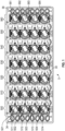
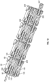
- FIG. 1 is a top view of a base plate 30 of a fluid processing cassette 5 (with top plate 10 (shown in FIG. 2 ) removed and not shown), which is an example fluid processing device according to an embodiment.
- cassette 5 comprises an input well 34, which is exemplary of the eight total input wells of cassette 5, and an output well 36, which is exemplary of the eight total output wells of cassette 5.
- Cassette 5 comprises eight separate fluid channels, and no fluid channel is in fluid communication with another fluid channel.
- Each of the eight input wells 34 is associated with a different fluid channel, and each of the eight output wells 36 is associated with a different fluid channel.
- Input well 34 and an associated output well 36 are associated with the same fluid channel, and the other input wells and output wells are likewise associated in pairs based on their positioning at proximal and distal ends of base plate 30.
- Base-plate pump control port 214 formed in base plate 30, which is exemplary of other base-plate pump control ports formed in base plate 30, is configured to permit a process plunger rod actuator 222 (described below, see FIGS. 36 , 38 , 39 ) to actuate internal fluid components via first and second process plunger rods 204, 206 (see FIG. 11 ).
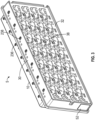
- FIG. 3 shows a bottom perspective view of cassette 5.
- a bottom portion of base plate 30 is sealed by base film 32.
- Base film 32 is shown as translucent in FIG. 3 so as to show features (e.g., process chamber 38) formed in the bottom of base plate 30, where the bottom surface of such features are sealed by base film 32.
- a plurality of process chambers 38 are formed in the bottom of base plate 30 and are configured to receive fluid at a particular processing station for a particular fluid channel.
- Process chamber 38 is exemplary of forty-eight total process chambers formed in base plate 30, of which eight are associated with the eight fluid channels (one process chamber per fluid channel) at each of six processing stations-i.e., first processing station 500 and first, second, third, fourth, and fifth intermediate processing stations 510, 520, 530, 540, and 550 (see FIG. 1 ).
- Top-plate rotor control port 236 formed in top plate 10 which is exemplary of other top-plate rotor control ports also formed in top plate 10, is configured to permit a reagent rotor rod actuator 240 (see FIGS. 36 , 37 , 39 ) to actuate internal fluid components via a reagent rotor rod 230 (see FIG. 15 ).
- Base-plate rotor control port 238 formed in base plate 30, which is exemplary of other base-plate rotor control ports formed in base plate 30, is configured to permit a process rotor rod actuator 242 (see FIG. 36 , 37 , 39 ) to actuate fluid components via a process rotor rod 232 (see FIG. 15 ). If reagent rotor rod actuator 240 is coupled to reagent rotor rod 230, retraction of reagent rotor rod actuator 240 out of and away from top-plate rotor control ports 236 a certain distance will cause reagent rotor rod actuator 240 to de-couple from reagent rotor rod 230 due to interference between reagent rotor rod 230 and top plate 10.
- An identification label 52 can comprise a machine-readable identification marker, such as a barcode or RFID tag, and/or a human-readable identification marker, such that sample fluids processed or sought to be processed in cassette 5 can be identified.
- a machine-readable identification marker such as a barcode or RFID tag
- a human-readable identification marker such that sample fluids processed or sought to be processed in cassette 5 can be identified.
- Top stator 80 further comprises at least one snap tab 81, which is a flexible tab with a detent configured to be snapped into a corresponding hole in top plate 10, such as to form a snap joint to secure top stator 80 and top plate 10 to each other.
- snap tab 81 is a flexible tab with a detent configured to be snapped into a corresponding hole in top plate 10, such as to form a snap joint to secure top stator 80 and top plate 10 to each other.
- Bottom stator 100 also comprises alignment holes 102 configured to receive alignment pins 123 (see FIG. 9 ) of stator seal 120.
- Bottom stator 100 further comprises at least one snap tab 101, which is a flexible tab with a detent configured to be snapped into a corresponding hole in base plate 30, such as to form a snap joint to secure bottom stator 100 and base plate 10 to each other.
- snap tab 101 is a flexible tab with a detent configured to be snapped into a corresponding hole in base plate 30, such as to form a snap joint to secure bottom stator 100 and base plate 10 to each other.
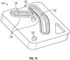
- stator seal 120 the top alignment pins 122, first top stator fluid path 130, and second top stator fluid path 132 on one surface of stator seal 120 and the bottom alignment pins 123, second bottom stator fluid path 138, and first bottom stator fluid path 136 on an opposite surface of stator seal 120 are mirrored features, respectively, on the opposite surfaces of stator seal 120.
- components of stator seal 120 are labelled as “top” or “bottom” for description purposes and are not so limited.
- either opposite surface of stator seal 120 can be aligned with and secured to the bottom of top stator 80 or the top of bottom stator 100.
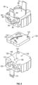
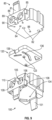
- Upper rotor 150 is substantially similar to lower rotor 170 (see FIG. 15 ), which is a component of the process pump assemblies of cassette 5, except that the top-facing portion of upper rotor 150 shown in FIG. 13 is equivalent to the bottom-facing portion of lower rotor 170.
- Lower rotors 170 in the second position allow the first and second process pump chambers 105, 109 to expel sample fluid to downstream portions of the fluid channels or to receive waste fluid from downstream portions of the fluid channels, again depending on the direction of movement of the first and second process plunger rods 204, 206, respectively.
- the upper rotors such as upper rotor 150 are all coupled to a single reagent rotor rod 230, via rotor connectors such as rotor connector 152, such that movement of reagent rotor rod 230 effects simultaneous movement of the upper rotors 150 between their first positions and second positions.
- Reagent rotor rod 230 comprises reagent rotor rod yoke 231, which is configured to operatively couple and de-couple reagent rotor rod 230 to reagent rotor rod actuator 240 (described below, see FIGS. 36 , 37 , 39 ).
- Process rotor rod 232 comprises process rotor rod yoke 233, which is configured to operatively couple and de-couple process rotor rod 232 to process rotor rod actuator 242 (described below, see FIG. 36 , 37 , 39 ).
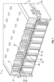
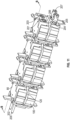
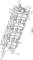
- FIG. 17 is an exploded top perspective view of the fluid processing cassette that shows the pump assemblies of each of first processing station 500, end processing station 560, and first, second, third, fourth, and fifth intermediate processing stations 510, 520, 530, 540, and 550.
- each processing station comprises the pump assemblies shown in FIG. 15 .
- reagent pump assemblies may be non-functional.
- First rotor-input fluid channel 310, first rotor-output fluid channel 330, and first process chamber 350 are all associated with the same fluid channel.
- Second rotor-input fluid channel 320, second rotor-output fluid channel 340, and second process chamber 360 are all associated with a different fluid channel.
- These channels, ports, inlets, and process chambers formed in the bottom of base plate 30 are sealed by base film 32, which is disposed onto a portion of the bottom of base plate 30.
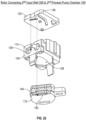
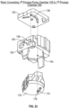
- first input well 307 is in fluid communication with first port 312 of first rotor-input fluid channel 310, of which the second port 314 is in fluid communication with the second rotor port 178 of lower rotor 170.
- a fluid can move from first input well 307 to second rotor port 178 of lower rotor 170 via first rotor-input fluid channel 310, as shown by a solid fluid path arrow in FIG. 20 .
- the fluid can then move from second rotor port 178 to first rotor port 176 via first rotor path 174 of lower rotor 170, as shown by a dashed fluid path arrow in FIG. 20 .
- second input well 308 is in fluid communication with first port 322 of second rotor-input fluid channel 320, of which the second port 324 is in fluid communication with a fourth rotor port 186 of lower rotor 170.
- a fluid can move from second input well 308 to fourth rotor port 186 of lower rotor 170 via second rotor-input fluid channel 320, as shown by a solid fluid path arrow in FIG. 20 .
- the fluid can then move from fourth rotor port 186 to third rotor port 184 via second rotor path 182 of lower rotor 170, as shown by a dashed fluid path arrow in FIG. 20 .
- lower rotor 170 is in its second position, which fluidly connects process pump chambers defined by the bottom stator 100 to which lower rotor 170 is coupled to downstream portions of the associated fluid channels, specifically first process chamber 350 and second process chamber 360.
- first rotor port 176 is in fluid communication with first port 332 of first rotor-output fluid channel 330, of which the first process chamber inlet 352 is in fluid communication with the first process chamber 350.
- the fluid can move from first rotor port 176 of lower rotor 170 to first process chamber 350 via first rotor-output fluid channel 330, as shown by a solid fluid path arrow in FIG. 26 . Therefore, when lower rotor 170 is in its second position, fluid can be moved along the first fluid channel from first process pump chamber 105 to first process chamber 350 by the process pump assembly associated with the first fluid channel.
- Dashed fluid path arrows in FIG. 24 show that a fluid in second process pump chamber 109 of bottom stator 100 can move through second process pump port 110, then along second bottom stator fluid path 138 of stator seal 120, then through second process rotor port 108 of bottom stator 100, and then through fourth rotor port 186 of lower rotor 170. As shown by FIGS. 25-26 , the fluid can then move from fourth rotor port 186 to third rotor port 184 via second rotor path 182 of lower rotor 170, as shown by a dashed fluid path arrow in FIG. 26 . As further shown by FIGS.
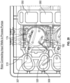
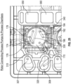
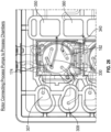
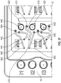
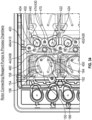
- FIGS. 28-29 and 34-35 are similar to FIG. 27 and additionally show upper rotor 150, specifically the top surface of upper rotor 150 that is disposed below the top surface of top plate 10, and gasket 403, which is disposed below a portion of the top plate 10 containing first and second reagent input wells 400, 420.
- first rotor port 156 shows that the fluid can then move down through first rotor port 156, then through first reagent rotor port 84 of top stator 80, then along first top stator fluid path 130 of stator seal 120, and then through first reagent pump port 86 into first reagent pump chamber 85 of top stator 80. Therefore, when upper rotor 150 is in its first position, fluid can be moved along a first fluid channel from first reagent input well 400 to first reagent pump chamber 85 by the process pump assembly associated with the first fluid channel.
- second reagent input well 4-20 is in fluid communication with second gasket slot 424 of gasket 403 via second reagent well port 422, and second gasket slot 424 is in fluid communication with second reagent-to-rotor port 426.
- a fluid can move from second reagent input well 420 to second reagent-to-rotor port 426 via second gasket slot 424, as shown by a dotted fluid path arrow in FIG. 29 .
- the fluid can then move up through second reagent-to-rotor port 426 to first port 452 of second rotor-input fluid channel 450, of which the second port 454 is in fluid communication with the fourth rotor port 166 of upper rotor 150.
- upper rotor 150 is in its second position, which fluidly connects reagent pump chambers defined by the top stator 80 to which upper rotor 150 is coupled to associated process chambers in the same processing station.
- first rotor port 156 is in fluid communication with first port 462 of first rotor-output fluid channel 460, of which the second port 464 is in fluid communication with first reagent-to-process chamber top-plate port 410.
- the fluid can move from first rotor port 156 of upper rotor 150 to first reagent-to-process chamber top-plate port 410, as shown by a solid fluid path arrow in FIG. 35 .
- first reagent-to-process chamber top-plate port 410 is connected to a process chamber 38 of the first fluid channel via a reagent-to-process chamber gasket port 66 and reagent-to-process chamber base-plate port 42 (see FIG. 7 ). Therefore, when upper rotor 150 is in its second position, fluid can be moved along the first fluid channel from first reagent pump chamber 85 to an associated process chamber by the process pump assembly associated with the first fluid channel.
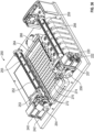
- FIG. 36 is a top perspective view of an actuator device 250 configured to actuate components of cassette 5 (discussed above).
- Cassette tray 264 is sized and configured to receive and retain base plate 30 of cassette 5.
- Reagent rotor rod actuator 240 is coupled to first linear rail 252 and configured to actuate reagent rotor rod 230 (see FIG. 15 ).
- Reagent rotor rod actuator 240 is configured to actuate a single reagent rotor rod 230 at a time, and first linear rail actuator 254 is configured to move reagent rotor rod actuator 240 along first linear rail 252 such that reagent rotor rod actuator 240 can be re-positioned to actuate the reagent rotor rod 230 of different processing stations of cassette 5 (e.g., first processing station 500, then each of first, second, third, fourth, and fifth intermediate processing stations 510, 520, 530, 540, 550, and then end processing station 560; see FIG. 1 ).
- Process rotor rod actuator 242 is coupled to first linear rail 252 and is configured to actuate process rotor rod 232 (see FIG. 15 ).
- second linear rail actuator 258 may comprise a rotary motor attached to a second rail actuator carriage 257 that is slidably coupled to a second actuator track 259 mounted to a base of the actuator device 250.
- Second linear rail 256 may comprise a threaded rod (lead screw) operatively attached to the second linear rail actuator 258 and threadably coupled to the second rail actuator carriage 257.
- the reagent plunger rod actuator 220 and the process plunger rod actuator 222, as well as magnet lift actuator 260 (see FIG. 41 ), are attached to the second rail actuator carriage 257.
- FIG. 37 is a perspective view of a reagent rotor rod actuator 240 and process rotor rod actuator 242 of actuator device 250.
- Reagent rotor rod actuator 240 comprises a reagent rotor rod actuator finger 244 that is (i) received and retained or (ii) released by reagent rotor rod yoke 231 of reagent rotor rod 230 (see FIG. 15 ) when reagent rotor rod actuator 240 is (i) coupled or (ii) de-coupled, respectively, to reagent rotor rod 230.
- Reagent rotor rod actuator finger 244 extends through top-plate rotor control port 236 (see FIGS.
- first and second reagent plunger rod actuator fingers 224, 225 are linearly extended and first and second process plunger rod actuator fingers 226, 227 are not extended (i.e., comparatively retracted).
- Reagent plunger rod actuator 220 can actuate first and second reagent plunger rods 200, 202 (see FIG.
- FIG. 39 is a top perspective view of cassette 5 positioned relative to reagent and process rotor rod actuators 240, 242, reagent and process plunger rod actuators 220, 222, and first and second linear rails 252, 256 of actuator device 250 such that these components of actuator device 250 are positioned to actuate the internal components of cassette 5.
- Cassette tray 264 of actuator device 250 is not shown in FIG. 39 (see FIG. 36 ).
- Reagent plunger rod actuator 220 actuates a set of first and second reagent plunger rods 200, 202 (see FIG.
- second linear rail actuator 258 moves second rail actuator carriage 257 along with process plunger rod actuator 222 to different positions along second linear rail 256 such that process plunger rod actuator 222 can actuate different sets of first and second process plunger rods 204, 206 via different pairs of base-plate pump control ports 214.
- reagent and process plunger rod actuators 220, 222 are located in a position on second linear rail 256 relative to cassette 5 so as to allow reagent and process plunger rod actuators 220, 222 to actuate first and second reagent plunger rods 200, 202 and first and second process plunger rods 204, 206 (see FIG. 11 ), respectively, of first processing station 500 (see FIG. 1 ) of cassette 5.
- first magnets 280 press against first flex circuit heater 270 and are proximate to process chambers 38 of first processing station 500 such that first magnets 280 apply a magnetic field to those process chambers 38 through the first flex circuit heater 270.
- first magnets 280 are relatively less proximate to those process chambers 38 such that first magnets 280 do not apply a magnetic field (or apply a weaker magnetic field) to those process chambers 38.
- Second magnets 290 are operatively associated with second magnet lifter 292 such that second magnet lifter 292 can be actuated to lift second magnets 290 into a first position or lower second magnets 290 into a second position.
- second magnets 290 press against second flex circuit heater 274 and are proximate to process chambers 38 of first intermediate processing station 510 such that second magnets 290 apply a magnetic field to those process chambers 38 through the second flex circuit heater 274.
- second magnets 290 are relatively less proximate to those process chambers 38 such that second magnets 290 do not apply a magnetic field (or apply a weaker magnetic field) to those process chambers 38.
- Second linear rail actuator 258 is configured to move magnet lift actuator 260 along second linear rail 256 such that magnet lift actuator 260 can be re-positioned to actuate the magnet lifter (e.g., first magnet lifter 282) of different processing stations of cassette 5 (e.g., first processing station 500, and then each of first, second, third, fourth, and fifth intermediate processing stations 510, 520, 530, 540, 550; see FIG. 1 )
- the magnet lifter e.g., first magnet lifter 282
- different processing stations of cassette 5 e.g., first processing station 500, and then each of first, second, third, fourth, and fifth intermediate processing stations 510, 520, 530, 540, 550; see FIG. 1 .
- cassette 5 specifically the process chambers 38, which pushes the portions of base film 32 that form the bottom surfaces of process chambers 38 against the top surface of first flex circuit heater 270 and the resistance heaters 272 thereof.
- each process chamber 38 of first processing station 500 corresponds to a first magnet 280, where rotating first magnet lifter pedal 284 downward or upward thereby rotates first magnet lifter 282, which lifts or lowers, respectively, first magnets 280 to perform magnet control of the process chambers 38.
- first magnets 280 When first magnets 280 are lifted to apply a magnetic field to process chambers 38, first magnets 280 press against the bottom surface of first flex circuit heater 270.
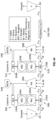
- the mixture is successively moved to intermediate processing stations 520, 530, 540, 550.
- reagent "C,” “D,” “E,” and “F,” respectively is added to the sample, and a process or reaction “C,” “D,” “E,” and “F” occurs within the intermediate processing station 520, 530, 540, 550, respectively.
- thermal control, magnetic control, or both is (are) applied to the sample/reagent mixture so as to effect one aspect of the process, such as promoting a reaction (e.g., an amplification or hybridization) or performing a magnetic separation procedure.
- End processing station 560 shown in FIG. 1 is not represented in FIG. 43 .
- End processing station 560 does not involve the addition of reagent to the sample mixture or a process or reaction occurring at the end process station 560 or the associated thermal and/or magnetic control, but instead only involves the movement of mixture from the last intermediate processing station 550 to the output well 36.
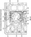
- the remaining intermediate process processing stations 520, 530, 540, 550 (columns C to F) would each be configured in substantially the same manner as first intermediate pump assembly column 511 of first intermediate processing station 510 and are not shown in detail in FIG. 44 .
- reaction chamber RB the order of adding sample mixture and reagent to reaction chamber RB may be reversed.
- a first valve of end processing station 560 (see FIG. 1 ) is configured to connect the reaction chamber of the penultimate processing station to the process pump chamber of end processing station 560.
- a process pump operable within the process pump chamber is activated to move an amount of sample mixture from the reaction chamber of the penultimate processing station to the process pump chamber of end processing station 560.
- the first valve of end processing station 560 is next configured to connect the process pump chamber of end processing station 560 to the output well 36, and the process pump is activated to move sample mixture from the process pump chamber to the output well 36.
Landscapes
- Chemical & Material Sciences (AREA)
- Engineering & Computer Science (AREA)
- General Engineering & Computer Science (AREA)
- Health & Medical Sciences (AREA)
- Dispersion Chemistry (AREA)
- Mechanical Engineering (AREA)
- General Health & Medical Sciences (AREA)
- Analytical Chemistry (AREA)
- Chemical Kinetics & Catalysis (AREA)
- Clinical Laboratory Science (AREA)
- Life Sciences & Earth Sciences (AREA)
- Biochemistry (AREA)
- Hematology (AREA)
- Physics & Mathematics (AREA)
- General Physics & Mathematics (AREA)
- Immunology (AREA)
- Pathology (AREA)
- Molecular Biology (AREA)
- Apparatus Associated With Microorganisms And Enzymes (AREA)
- Automatic Analysis And Handling Materials Therefor (AREA)
- Measuring Or Testing Involving Enzymes Or Micro-Organisms (AREA)
Claims (9)
- Dispositif de traitement de fluide comprenant :une pluralité de canaux de fluide comprenant un premier ensemble de deux canaux de fluide ou plus et un second ensemble de deux canaux de fluide ou plus ;un puits d'entrée d'échantillon (34, 307, 308) associé à chacun de la pluralité de canaux de fluide ;un puits de sortie d'échantillon (36) associé à chacun de la pluralité de canaux de fluide ; etau moins une station de traitement initiale (500) comprenant :un premier ensemble pompe de traitement initial associé à chacun des deux canaux de fluide ou plus du premier ensemble ;un second ensemble pompe de traitement initial associé à chacun des deux canaux de fluide ou plus du second ensemble ;une chambre de traitement initiale (38, 350, 360) associée à chacun de la pluralité de canaux de fluide,dans lequel les premiers ensembles pompes de traitement initiaux de la station de traitement initiale sont configurés pour pouvoir fonctionner à l'unisson afin de déplacer simultanément un échantillon de fluide à partir de chaque puits d'entrée d'échantillon du canal de fluide associé du premier ensemble à travers une partie de chaque canal de fluide associé du premier ensemble etdans chaque chambre de traitement initiale associée, et les seconds ensembles pompes de traitement initiaux sont configurés pour pouvoir fonctionner à l'unisson afin de déplacer simultanément un échantillon de fluide à partir de chaque puits d'entrée d'échantillon du canal de fluide associé du second ensemble à travers une partie de chaque canal de fluide associé du second ensemble et dans chaque chambre de traitement initiale associée ;un premier ensemble pompe à réactif initial associé à chacun des deux canaux de fluide ou plus du premier ensemble et un second ensemble pompe à réactif initial associé à chacun des deux canaux de fluide ou plus du second ensemble ;un puits d'entrée de réactif initial (14, 400, 402) associé à chacun de la pluralité de canaux de fluide ; etun canal de réactif initial associé à chaque puits d'entrée de réactif initial connectant le puits d'entrée de réactif initial à la chambre de traitement initiale du canal de fluide associé,dans lequel les premiers ensembles pompes à réactif initiaux sont configurés pour pouvoir fonctionner à l'unisson afin de déplacer simultanément un réactif à partir de chaque puits d'entrée de réactif initial du canal de fluide associé du premier ensemble à travers le canal de réactif initial associé et dans chaque chambre de traitement initiale du canal de fluide associé du premier ensemble, et les seconds ensembles pompes à réactif initiaux sont configurés pour pouvoir fonctionner à l'unisson afin de déplacer simultanément un réactif à partir de chaque puits d'entrée de réactif initial du canal de fluide associé du second ensemble à travers le canal de réactif initial associé et dans chaque chambre de traitement initiale du canal de fluide associé du second ensemble ;une station de traitement terminale (560) comprenant :un premier ensemble pompe de traitement terminal associé à chacun des deux canaux de fluide ou plus du premier ensemble ; etun second ensemble pompe de traitement terminal associé à chacun des deux canaux de fluide ou plus du second ensemble, dans lequel les premiers ensembles pompes de traitement terminaux de la station de traitement terminale sont configurés pour pouvoir fonctionner à l'unisson afin de déplacer simultanément un fluide à travers une partie de chaque canal de fluide associé du premier ensemble et dans chaque puits de sortie d'échantillon du canal de fluide associé du premier ensemble, et les seconds ensembles pompes de traitement terminaux de la station de traitement terminale sont configurés pour pouvoir fonctionner à l'unisson afin de déplacer simultanément un fluide à travers une partie de chaque canal de fluide associé du second ensemble et dans chaque puits de sortie d'échantillon du canal de fluide associé du second ensemble ; etune ou plusieurs stations de traitement intermédiaires (510, 520, 530, 540, 550) disposées entre la station de traitement initiale et la station de traitement terminale,dans lequel chaque station de traitement intermédiaire comprend :un premier ensemble pompe de traitement intermédiaire associé à chacun des deux canaux de fluide ou plus du premier ensemble ;un second ensemble pompe de traitement intermédiaire associé à chacun des deux canaux de fluide ou plus du second ensemble ;une chambre de traitement intermédiaire (38, 350, 360) associée à chacun de la pluralité de canaux de fluide,dans lequel les premiers ensembles pompes de traitement intermédiaires de chaque station de traitement intermédiaire sont configurés pour pouvoir fonctionner à l'unisson afin de déplacer simultanément un fluide à partir d'une chambre de traitement d'une station précédente des stations de traitement à travers une partie de chaque canal de fluide associé du premier ensemble et dans chaque chambre de traitement intermédiaire associée du premier ensemble, et dans lequel les seconds ensembles pompes de traitement intermédiaires de chaque station de traitement intermédiaire sont configurés pour pouvoir fonctionner à l'unisson afin de déplacer simultanément un fluide à partir d'une chambre de traitement de la station de traitement précédente à travers une partie de chaque canal de fluide associé du second ensemble et dans chaque chambre de traitement intermédiaire associée du second ensemble ;un premier ensemble pompe à réactif intermédiaire associé à chacun des deux canaux de fluide ou plus du premier ensemble et un second ensemble pompe à réactif intermédiaire associé à chacun des deux canaux de fluide ou plus du second ensemble ;un puits d'entrée de réactif intermédiaire (14, 400, 402) associé à chacun de la pluralité de canaux de fluide ; etun canal de réactif intermédiaire associé à chaque puits d'entrée de réactif intermédiaire connectant le puits d'entrée de réactif intermédiaire à la chambre de traitement intermédiaire du canal de fluide associé,dans lequel les premiers ensembles pompes à réactif intermédiaires de la station de traitement intermédiaire sont configurés pour pouvoir fonctionner à l'unisson afin de déplacer simultanément un réactif à partir de chaque puits d'entrée de réactif intermédiaire du canal de fluide associé du premier ensemble à travers le canal de réactif intermédiaire associé et dans chaque chambre de traitement intermédiaire du canal de fluide associé du premier ensemble, et les seconds ensembles pompes à réactif intermédiaires de la station de traitement intermédiaire sont configurés pour pouvoir fonctionner à l'unisson afin de déplacer simultanément un réactif à partir de chaque puits d'entrée de réactif intermédiaire du canal de fluide associé du second ensemble à travers le canal de réactif intermédiaire associé et dans chaque chambre de traitement intermédiaire du canal de fluide associé du second ensemble.
- Dispositif de traitement de fluide selon la revendication 1, comprenant cinq stations de traitement intermédiaires disposées entre la station de traitement initiale et la station de traitement terminale.
- Dispositif de traitement de fluide selon la revendication 1, dans lequel chacun des premier et second ensembles pompes de traitement de chacune des stations de traitement initiale, intermédiaire et terminale comprend :deux stators de traitement ou plus (100), dans lequel chaque stator de traitement définit des première et seconde chambres de pompe de traitement (105, 109) et des premiers et seconds orifices de chambre de traitement (104, 108) en communication fluidique avec les première et seconde chambres de pompe de traitement, respectivement ;un piston de traitement (209) disposé à l'intérieur de chaque première et seconde chambre de pompe de traitement, dans lequel les pistons de traitement disposés à l'intérieur des premières chambres de pompe de traitement sont connectés à une première tige de piston de traitement (204), et les pistons de traitement disposés à l'intérieur des secondes chambres de pompe de traitement sont connectés à une seconde tige de piston de traitement (206),dans lequel les pistons de traitement disposés à l'intérieur des premières chambres de pompe de traitement sont mobiles via la première tige de piston de traitement dans une première direction pour aspirer simultanément du fluide dans les premières chambres de pompe de traitement à travers les premiers orifices de chambre de traitement associés ou dans une seconde direction pour expulser simultanément du fluide à partir des premières chambres de pompe de traitement à travers les premiers orifices de chambre de traitement associés, et dans lequel les pistons de traitement disposés à l'intérieur des secondes chambres de pompe de traitement sont mobiles via la seconde tige de piston de traitement dans une première direction pour aspirer simultanément du fluide dans les secondes chambres de pompe de traitement à travers les seconds orifices de chambre de traitement associés ou dans une seconde direction pour expulser simultanément du fluide à partir des secondes chambres de pompe de traitement à travers les seconds orifices de chambre de traitement associés ; etune vanne de traitement couplée à chaque stator de traitement et mobile entre une première position connectant de manière fluidique les premiers et seconds orifices de chambre de traitement à une partie amont de chaque canal de fluide associé et une seconde position connectant de manière fluidique les premiers et seconds orifices de chambre de traitement à une partie aval de chaque canal de fluide associé, dans lequel la partie aval du canal de fluide associé est en communication fluidique avec la chambre de traitement associée ou le puits de sortie d'échantillon associé.
- Dispositif de traitement de fluide selon la revendication 3, dans lequel la vanne de traitement comprend un rotor (170) qui est monté rotatif par rapport au stator de traitement pour un mouvement de rotation entre la première position et la seconde position.
- Dispositif de traitement de fluide selon l'une quelconque des revendications 1 à 4, dans lequel chacun des premier et second ensembles pompes de traitement de chacune des stations de traitement initiales et intermédiaires comprend :deux stators de réactif ou plus (80), dans lequel chaque stator de réactif définit des première et seconde chambres de pompe à réactif (85, 89) et des premiers et seconds orifices de chambre à réactif (84, 88) en communication fluidique avec les première et seconde chambres de pompe à réactif, respectivement ;un piston de réactif (208) disposé à l'intérieur de chaque première et seconde chambre de pompe à réactif, dans lequel les pistons de réactif disposés à l'intérieur des premières chambres de pompe à réactif sont connectés à une première tige de piston de réactif (201), et les pistons de réactif disposés à l'intérieur des secondes chambres de pompe à réactif sont connectés à une seconde tige de piston de réactif (202),dans lequel les pistons de réactif disposés à l'intérieur des premières chambres de pompe à réactif sont mobiles via la première tige de piston de réactif dans une première direction aspirant du fluide dans les premières chambres de pompe à réactif à travers les premiers orifices de chambre à réactif ou dans une seconde direction expulsant du fluide à partir des premières chambres de pompe à réactif à travers les premiers orifices de chambre à réactif, et les pistons de réactif disposés à l'intérieur des secondes chambres de pompe à réactif sont mobiles via la seconde tige de piston de réactif dans une première direction aspirant du fluide dans les secondes chambres de pompe à réactif à travers les seconds orifices de chambre à réactif ou dans une seconde direction expulsant du fluide à partir des secondes chambres de pompe à réactif à travers les seconds orifices de chambre à réactif ; etune vanne de réactif couplée au stator de réactif et mobile entre une première position connectant de manière fluidique les premiers et seconds orifices de chambre à réactif aux premier et second puits d'entrée de réactif associés et une seconde position connectant de manière fluidique les premiers et seconds orifices de chambre à réactif aux chambres de traitement associées.
- Dispositif de traitement de fluide selon la revendication 5, dans lequel la vanne de réactif comprend un rotor (150) qui est monté rotatif par rapport au stator de réactif pour un mouvement de rotation entre la première position et la seconde position.
- Dispositif de traitement selon l'une quelconque des revendications 3 à 5, dans lequel les premier et second ensembles pompes de traitement de chacune des stations de traitement initiale, intermédiaire et terminale comprennent une tige de vanne de traitement (232), et l'ensemble des vannes de traitement des ensembles pompes de traitement de chaque station de traitement sont couplées à la tige de vanne de traitement, de sorte qu'un mouvement de la tige de vanne de traitement provoque un mouvement simultané des vannes de traitement entre leurs première et seconde positions respectives.
- Dispositif de traitement selon l'une quelconque des revendications 3 à 7, dans lequel les ensembles pompes à réactif de chacune des stations de traitement initiales et intermédiaires comprennent une tige de vanne de réactif (230), et l'ensemble des vannes de réactif des ensembles pompes à réactif de chaque station de traitement sont couplées à la tige de vanne de réactif, de sorte que le mouvement de la tige de vanne de réactif provoque un mouvement simultané des vannes de réactif entre leurs première et seconde positions respectives.
- Dispositif de traitement selon l'une quelconque des revendications 1 à 8, comprenant huit canaux de fluide.
Applications Claiming Priority (2)
| Application Number | Priority Date | Filing Date | Title |
|---|---|---|---|
| US201962852719P | 2019-05-24 | 2019-05-24 | |
| PCT/US2020/017202 WO2020242544A1 (fr) | 2019-05-24 | 2020-02-07 | Dispositif et procédé de traitement de fluide |
Publications (3)
| Publication Number | Publication Date |
|---|---|
| EP3976257A1 EP3976257A1 (fr) | 2022-04-06 |
| EP3976257A4 EP3976257A4 (fr) | 2023-06-07 |
| EP3976257B1 true EP3976257B1 (fr) | 2025-04-09 |
Family
ID=73553493
Family Applications (1)
| Application Number | Title | Priority Date | Filing Date |
|---|---|---|---|
| EP20813546.7A Active EP3976257B1 (fr) | 2019-05-24 | 2020-02-07 | Dispositif et procédé de traitement de fluide |
Country Status (4)
| Country | Link |
|---|---|
| US (1) | US12535497B2 (fr) |
| EP (1) | EP3976257B1 (fr) |
| JP (1) | JP7550460B2 (fr) |
| WO (1) | WO2020242544A1 (fr) |
Family Cites Families (6)
| Publication number | Priority date | Publication date | Assignee | Title |
|---|---|---|---|---|
| ATE429482T1 (de) | 2001-12-31 | 2009-05-15 | Trinity College Dublin | Vorrichtung zur durchführung von auf zellen basierende analyseverfahren |
| KR20110111449A (ko) * | 2008-12-31 | 2011-10-11 | 인터젠엑스 인크. | 미세유체 칩을 갖는 기구 |
| US8720036B2 (en) * | 2010-03-09 | 2014-05-13 | Netbio, Inc. | Unitary biochip providing sample-in to results-out processing and methods of manufacture |
| CN103097883B (zh) * | 2010-03-09 | 2016-03-02 | 网络百奥有限公司 | 提供样本输入至结果输出处理的单体生物芯片以及制造方法 |
| EP2606154B1 (fr) * | 2010-08-20 | 2019-09-25 | Integenx Inc. | Système d'analyse intégrée |
| US11300578B2 (en) | 2016-09-19 | 2022-04-12 | Roche Molecular Systems, Inc. | Instrument for processing cartridge for performing assays in a closed sample preparation and reaction system |
-
2020
- 2020-02-07 WO PCT/US2020/017202 patent/WO2020242544A1/fr not_active Ceased
- 2020-02-07 EP EP20813546.7A patent/EP3976257B1/fr active Active
- 2020-02-07 JP JP2021569936A patent/JP7550460B2/ja active Active
- 2020-02-07 US US17/612,166 patent/US12535497B2/en active Active
Also Published As
| Publication number | Publication date |
|---|---|
| US12535497B2 (en) | 2026-01-27 |
| JP7550460B2 (ja) | 2024-09-13 |
| US20220206030A1 (en) | 2022-06-30 |
| EP3976257A1 (fr) | 2022-04-06 |
| EP3976257A4 (fr) | 2023-06-07 |
| JP2022535716A (ja) | 2022-08-10 |
| WO2020242544A1 (fr) | 2020-12-03 |
Similar Documents
| Publication | Publication Date | Title |
|---|---|---|
| US20220023862A1 (en) | Microfluidic cartridge for processing and detecting nucleic acids | |
| US20240359177A1 (en) | Valve actuator for microfluidic cartridge | |
| JP6908671B2 (ja) | 分析評価カートリッジのバルブシステム | |
| US8691592B2 (en) | Mechanically actuated diagnostic device | |
| US8323887B2 (en) | Miniaturized fluid delivery and analysis system | |
| US11485968B2 (en) | Microfluidic cartridge for processing and detecting nucleic acids | |
| WO2011151804A1 (fr) | Système et ensemble d'interface fluidique | |
| EP3976257B1 (fr) | Dispositif et procédé de traitement de fluide | |
| US12115530B2 (en) | On-board reagent storage in a fluid processing device | |
| CN218811744U (zh) | 一种微流控pcr芯片 | |
| US20250073701A1 (en) | Integrated valve body and syringe tube component for assay cartridges | |
| US20230278026A1 (en) | Device and method for inhibiting cross contamination for diagnostic assay system | |
| AU2023236548A1 (en) | Unitary cartridge body and associated components and methods of manufacture | |
| WO2023220055A1 (fr) | Systèmes et procédés de manipulation et de transfert de fluides de manière aseptique par le biais de composants microfluidiques |
Legal Events
| Date | Code | Title | Description |
|---|---|---|---|
| STAA | Information on the status of an ep patent application or granted ep patent |
Free format text: STATUS: THE INTERNATIONAL PUBLICATION HAS BEEN MADE |
|
| PUAI | Public reference made under article 153(3) epc to a published international application that has entered the european phase |
Free format text: ORIGINAL CODE: 0009012 |
|
| STAA | Information on the status of an ep patent application or granted ep patent |
Free format text: STATUS: REQUEST FOR EXAMINATION WAS MADE |
|
| 17P | Request for examination filed |
Effective date: 20211222 |
|
| AK | Designated contracting states |
Kind code of ref document: A1 Designated state(s): AL AT BE BG CH CY CZ DE DK EE ES FI FR GB GR HR HU IE IS IT LI LT LU LV MC MK MT NL NO PL PT RO RS SE SI SK SM TR |
|
| DAV | Request for validation of the european patent (deleted) | ||
| DAX | Request for extension of the european patent (deleted) | ||
| A4 | Supplementary search report drawn up and despatched |
Effective date: 20230508 |
|
| RIC1 | Information provided on ipc code assigned before grant |
Ipc: G01N 35/00 20060101ALI20230428BHEP Ipc: G01N 33/53 20060101ALI20230428BHEP Ipc: G01N 33/50 20060101ALI20230428BHEP Ipc: G01N 33/48 20060101ALI20230428BHEP Ipc: B01L 3/00 20060101AFI20230428BHEP |
|
| GRAP | Despatch of communication of intention to grant a patent |
Free format text: ORIGINAL CODE: EPIDOSNIGR1 |
|
| STAA | Information on the status of an ep patent application or granted ep patent |
Free format text: STATUS: GRANT OF PATENT IS INTENDED |
|
| INTG | Intention to grant announced |
Effective date: 20241126 |
|
| GRAS | Grant fee paid |
Free format text: ORIGINAL CODE: EPIDOSNIGR3 |
|
| GRAA | (expected) grant |
Free format text: ORIGINAL CODE: 0009210 |
|
| STAA | Information on the status of an ep patent application or granted ep patent |
Free format text: STATUS: THE PATENT HAS BEEN GRANTED |
|
| AK | Designated contracting states |
Kind code of ref document: B1 Designated state(s): AL AT BE BG CH CY CZ DE DK EE ES FI FR GB GR HR HU IE IS IT LI LT LU LV MC MK MT NL NO PL PT RO RS SE SI SK SM TR |
|
| REG | Reference to a national code |
Ref country code: GB Ref legal event code: FG4D |
|
| REG | Reference to a national code |
Ref country code: CH Ref legal event code: EP |
|
| REG | Reference to a national code |
Ref country code: DE Ref legal event code: R096 Ref document number: 602020049209 Country of ref document: DE |
|
| REG | Reference to a national code |
Ref country code: IE Ref legal event code: FG4D |
|
| REG | Reference to a national code |
Ref country code: NL Ref legal event code: MP Effective date: 20250409 |
|
| PG25 | Lapsed in a contracting state [announced via postgrant information from national office to epo] |
Ref country code: NL Free format text: LAPSE BECAUSE OF FAILURE TO SUBMIT A TRANSLATION OF THE DESCRIPTION OR TO PAY THE FEE WITHIN THE PRESCRIBED TIME-LIMIT Effective date: 20250409 |
|
| REG | Reference to a national code |
Ref country code: AT Ref legal event code: MK05 Ref document number: 1783082 Country of ref document: AT Kind code of ref document: T Effective date: 20250409 |
|
| PG25 | Lapsed in a contracting state [announced via postgrant information from national office to epo] |
Ref country code: FI Free format text: LAPSE BECAUSE OF FAILURE TO SUBMIT A TRANSLATION OF THE DESCRIPTION OR TO PAY THE FEE WITHIN THE PRESCRIBED TIME-LIMIT Effective date: 20250409 Ref country code: ES Free format text: LAPSE BECAUSE OF FAILURE TO SUBMIT A TRANSLATION OF THE DESCRIPTION OR TO PAY THE FEE WITHIN THE PRESCRIBED TIME-LIMIT Effective date: 20250409 Ref country code: PT Free format text: LAPSE BECAUSE OF FAILURE TO SUBMIT A TRANSLATION OF THE DESCRIPTION OR TO PAY THE FEE WITHIN THE PRESCRIBED TIME-LIMIT Effective date: 20250811 |
|
| REG | Reference to a national code |
Ref country code: LT Ref legal event code: MG9D |
|
| PG25 | Lapsed in a contracting state [announced via postgrant information from national office to epo] |
Ref country code: GR Free format text: LAPSE BECAUSE OF FAILURE TO SUBMIT A TRANSLATION OF THE DESCRIPTION OR TO PAY THE FEE WITHIN THE PRESCRIBED TIME-LIMIT Effective date: 20250710 Ref country code: NO Free format text: LAPSE BECAUSE OF FAILURE TO SUBMIT A TRANSLATION OF THE DESCRIPTION OR TO PAY THE FEE WITHIN THE PRESCRIBED TIME-LIMIT Effective date: 20250709 |
|
| PG25 | Lapsed in a contracting state [announced via postgrant information from national office to epo] |
Ref country code: PL Free format text: LAPSE BECAUSE OF FAILURE TO SUBMIT A TRANSLATION OF THE DESCRIPTION OR TO PAY THE FEE WITHIN THE PRESCRIBED TIME-LIMIT Effective date: 20250409 |
|
| PG25 | Lapsed in a contracting state [announced via postgrant information from national office to epo] |
Ref country code: BG Free format text: LAPSE BECAUSE OF FAILURE TO SUBMIT A TRANSLATION OF THE DESCRIPTION OR TO PAY THE FEE WITHIN THE PRESCRIBED TIME-LIMIT Effective date: 20250409 |
|
| PG25 | Lapsed in a contracting state [announced via postgrant information from national office to epo] |
Ref country code: HR Free format text: LAPSE BECAUSE OF FAILURE TO SUBMIT A TRANSLATION OF THE DESCRIPTION OR TO PAY THE FEE WITHIN THE PRESCRIBED TIME-LIMIT Effective date: 20250409 |
|
| PG25 | Lapsed in a contracting state [announced via postgrant information from national office to epo] |
Ref country code: AT Free format text: LAPSE BECAUSE OF FAILURE TO SUBMIT A TRANSLATION OF THE DESCRIPTION OR TO PAY THE FEE WITHIN THE PRESCRIBED TIME-LIMIT Effective date: 20250409 |
|
| PG25 | Lapsed in a contracting state [announced via postgrant information from national office to epo] |
Ref country code: RS Free format text: LAPSE BECAUSE OF FAILURE TO SUBMIT A TRANSLATION OF THE DESCRIPTION OR TO PAY THE FEE WITHIN THE PRESCRIBED TIME-LIMIT Effective date: 20250709 |
|
| PG25 | Lapsed in a contracting state [announced via postgrant information from national office to epo] |
Ref country code: IS Free format text: LAPSE BECAUSE OF FAILURE TO SUBMIT A TRANSLATION OF THE DESCRIPTION OR TO PAY THE FEE WITHIN THE PRESCRIBED TIME-LIMIT Effective date: 20250809 |
|
| PG25 | Lapsed in a contracting state [announced via postgrant information from national office to epo] |
Ref country code: LV Free format text: LAPSE BECAUSE OF FAILURE TO SUBMIT A TRANSLATION OF THE DESCRIPTION OR TO PAY THE FEE WITHIN THE PRESCRIBED TIME-LIMIT Effective date: 20250409 |
|
| REG | Reference to a national code |
Ref country code: DE Ref legal event code: R097 Ref document number: 602020049209 Country of ref document: DE |
|
| PG25 | Lapsed in a contracting state [announced via postgrant information from national office to epo] |
Ref country code: DK Free format text: LAPSE BECAUSE OF FAILURE TO SUBMIT A TRANSLATION OF THE DESCRIPTION OR TO PAY THE FEE WITHIN THE PRESCRIBED TIME-LIMIT Effective date: 20250409 Ref country code: SM Free format text: LAPSE BECAUSE OF FAILURE TO SUBMIT A TRANSLATION OF THE DESCRIPTION OR TO PAY THE FEE WITHIN THE PRESCRIBED TIME-LIMIT Effective date: 20250409 |
|
| PG25 | Lapsed in a contracting state [announced via postgrant information from national office to epo] |
Ref country code: CZ Free format text: LAPSE BECAUSE OF FAILURE TO SUBMIT A TRANSLATION OF THE DESCRIPTION OR TO PAY THE FEE WITHIN THE PRESCRIBED TIME-LIMIT Effective date: 20250409 |
|
| PG25 | Lapsed in a contracting state [announced via postgrant information from national office to epo] |
Ref country code: EE Free format text: LAPSE BECAUSE OF FAILURE TO SUBMIT A TRANSLATION OF THE DESCRIPTION OR TO PAY THE FEE WITHIN THE PRESCRIBED TIME-LIMIT Effective date: 20250409 |
|
| PG25 | Lapsed in a contracting state [announced via postgrant information from national office to epo] |
Ref country code: SK Free format text: LAPSE BECAUSE OF FAILURE TO SUBMIT A TRANSLATION OF THE DESCRIPTION OR TO PAY THE FEE WITHIN THE PRESCRIBED TIME-LIMIT Effective date: 20250409 Ref country code: RO Free format text: LAPSE BECAUSE OF FAILURE TO SUBMIT A TRANSLATION OF THE DESCRIPTION OR TO PAY THE FEE WITHIN THE PRESCRIBED TIME-LIMIT Effective date: 20250409 |
|
| PG25 | Lapsed in a contracting state [announced via postgrant information from national office to epo] |
Ref country code: IT Free format text: LAPSE BECAUSE OF FAILURE TO SUBMIT A TRANSLATION OF THE DESCRIPTION OR TO PAY THE FEE WITHIN THE PRESCRIBED TIME-LIMIT Effective date: 20250409 |
|
| PLBE | No opposition filed within time limit |
Free format text: ORIGINAL CODE: 0009261 |
|
| STAA | Information on the status of an ep patent application or granted ep patent |
Free format text: STATUS: NO OPPOSITION FILED WITHIN TIME LIMIT |
|
| REG | Reference to a national code |
Ref country code: CH Ref legal event code: L10 Free format text: ST27 STATUS EVENT CODE: U-0-0-L10-L00 (AS PROVIDED BY THE NATIONAL OFFICE) Effective date: 20260218 |
|
| REG | Reference to a national code |
Ref country code: CH Ref legal event code: U11 Free format text: ST27 STATUS EVENT CODE: U-0-0-U10-U11 (AS PROVIDED BY THE NATIONAL OFFICE) Effective date: 20260301 |
|
| 26N | No opposition filed |
Effective date: 20260112 |
|
| PGFP | Annual fee paid to national office [announced via postgrant information from national office to epo] |
Ref country code: GB Payment date: 20260209 Year of fee payment: 7 |
|
| PGFP | Annual fee paid to national office [announced via postgrant information from national office to epo] |
Ref country code: DE Payment date: 20260211 Year of fee payment: 7 |
|
| PGFP | Annual fee paid to national office [announced via postgrant information from national office to epo] |
Ref country code: BE Payment date: 20260216 Year of fee payment: 7 |
|
| PGFP | Annual fee paid to national office [announced via postgrant information from national office to epo] |
Ref country code: FR Payment date: 20260209 Year of fee payment: 7 |
|
| PGFP | Annual fee paid to national office [announced via postgrant information from national office to epo] |
Ref country code: CH Payment date: 20260301 Year of fee payment: 7 |