EP3976261B1 - Procédé de détection d'un acide nucléique cible dans un échantillon et dispositif de détection d'une réaction d'acide nucléique - Google Patents
Procédé de détection d'un acide nucléique cible dans un échantillon et dispositif de détection d'une réaction d'acide nucléique Download PDFInfo
- Publication number
- EP3976261B1 EP3976261B1 EP20812734.0A EP20812734A EP3976261B1 EP 3976261 B1 EP3976261 B1 EP 3976261B1 EP 20812734 A EP20812734 A EP 20812734A EP 3976261 B1 EP3976261 B1 EP 3976261B1
- Authority
- EP
- European Patent Office
- Prior art keywords
- reaction
- sample
- reaction area
- nucleic acid
- sample set
- Prior art date
- Legal status (The legal status is an assumption and is not a legal conclusion. Google has not performed a legal analysis and makes no representation as to the accuracy of the status listed.)
- Active
Links
Images


Classifications
-
- B—PERFORMING OPERATIONS; TRANSPORTING
- B01—PHYSICAL OR CHEMICAL PROCESSES OR APPARATUS IN GENERAL
- B01L—CHEMICAL OR PHYSICAL LABORATORY APPARATUS FOR GENERAL USE
- B01L7/00—Heating or cooling apparatus; Heat insulating devices
- B01L7/52—Heating or cooling apparatus; Heat insulating devices with provision for submitting samples to a predetermined sequence of different temperatures, e.g. for treating nucleic acid samples
-
- B—PERFORMING OPERATIONS; TRANSPORTING
- B01—PHYSICAL OR CHEMICAL PROCESSES OR APPARATUS IN GENERAL
- B01L—CHEMICAL OR PHYSICAL LABORATORY APPARATUS FOR GENERAL USE
- B01L3/00—Containers or dishes for laboratory use, e.g. laboratory glassware; Droppers
- B01L3/50—Containers for the purpose of retaining a material to be analysed, e.g. test tubes
- B01L3/508—Rigid containers without fluid transport within
- B01L3/5085—Rigid containers without fluid transport within for multiple samples, e.g. microtitration plates
- B01L3/50851—Rigid containers without fluid transport within for multiple samples, e.g. microtitration plates specially adapted for heating or cooling samples
-
- C—CHEMISTRY; METALLURGY
- C12—BIOCHEMISTRY; BEER; SPIRITS; WINE; VINEGAR; MICROBIOLOGY; ENZYMOLOGY; MUTATION OR GENETIC ENGINEERING
- C12Q—MEASURING OR TESTING PROCESSES INVOLVING ENZYMES, NUCLEIC ACIDS OR MICROORGANISMS; COMPOSITIONS OR TEST PAPERS THEREFOR; PROCESSES OF PREPARING SUCH COMPOSITIONS; CONDITION-RESPONSIVE CONTROL IN MICROBIOLOGICAL OR ENZYMOLOGICAL PROCESSES
- C12Q1/00—Measuring or testing processes involving enzymes, nucleic acids or microorganisms; Compositions therefor; Processes of preparing such compositions
- C12Q1/68—Measuring or testing processes involving enzymes, nucleic acids or microorganisms; Compositions therefor; Processes of preparing such compositions involving nucleic acids
- C12Q1/6813—Hybridisation assays
- C12Q1/6816—Hybridisation assays characterised by the detection means
-
- C—CHEMISTRY; METALLURGY
- C12—BIOCHEMISTRY; BEER; SPIRITS; WINE; VINEGAR; MICROBIOLOGY; ENZYMOLOGY; MUTATION OR GENETIC ENGINEERING
- C12Q—MEASURING OR TESTING PROCESSES INVOLVING ENZYMES, NUCLEIC ACIDS OR MICROORGANISMS; COMPOSITIONS OR TEST PAPERS THEREFOR; PROCESSES OF PREPARING SUCH COMPOSITIONS; CONDITION-RESPONSIVE CONTROL IN MICROBIOLOGICAL OR ENZYMOLOGICAL PROCESSES
- C12Q1/00—Measuring or testing processes involving enzymes, nucleic acids or microorganisms; Compositions therefor; Processes of preparing such compositions
- C12Q1/68—Measuring or testing processes involving enzymes, nucleic acids or microorganisms; Compositions therefor; Processes of preparing such compositions involving nucleic acids
- C12Q1/6844—Nucleic acid amplification reactions
- C12Q1/686—Polymerase chain reaction [PCR]
-
- G—PHYSICS
- G01—MEASURING; TESTING
- G01N—INVESTIGATING OR ANALYSING MATERIALS BY DETERMINING THEIR CHEMICAL OR PHYSICAL PROPERTIES
- G01N21/00—Investigating or analysing materials by the use of optical means, i.e. using sub-millimetre waves, infrared, visible or ultraviolet light
- G01N21/01—Arrangements or apparatus for facilitating the optical investigation
-
- G—PHYSICS
- G01—MEASURING; TESTING
- G01N—INVESTIGATING OR ANALYSING MATERIALS BY DETERMINING THEIR CHEMICAL OR PHYSICAL PROPERTIES
- G01N21/00—Investigating or analysing materials by the use of optical means, i.e. using sub-millimetre waves, infrared, visible or ultraviolet light
- G01N21/62—Systems in which the material investigated is excited whereby it emits light or causes a change in wavelength of the incident light
- G01N21/63—Systems in which the material investigated is excited whereby it emits light or causes a change in wavelength of the incident light optically excited
- G01N21/64—Fluorescence; Phosphorescence
- G01N21/6408—Fluorescence; Phosphorescence with measurement of decay time, time resolved fluorescence
-
- G—PHYSICS
- G01—MEASURING; TESTING
- G01N—INVESTIGATING OR ANALYSING MATERIALS BY DETERMINING THEIR CHEMICAL OR PHYSICAL PROPERTIES
- G01N21/00—Investigating or analysing materials by the use of optical means, i.e. using sub-millimetre waves, infrared, visible or ultraviolet light
- G01N21/62—Systems in which the material investigated is excited whereby it emits light or causes a change in wavelength of the incident light
- G01N21/63—Systems in which the material investigated is excited whereby it emits light or causes a change in wavelength of the incident light optically excited
- G01N21/64—Fluorescence; Phosphorescence
- G01N21/6428—Measuring fluorescence of fluorescent products of reactions or of fluorochrome labelled reactive substances, e.g. measuring quenching effects, using measuring "optrodes"
-
- G—PHYSICS
- G01—MEASURING; TESTING
- G01N—INVESTIGATING OR ANALYSING MATERIALS BY DETERMINING THEIR CHEMICAL OR PHYSICAL PROPERTIES
- G01N21/00—Investigating or analysing materials by the use of optical means, i.e. using sub-millimetre waves, infrared, visible or ultraviolet light
- G01N21/62—Systems in which the material investigated is excited whereby it emits light or causes a change in wavelength of the incident light
- G01N21/63—Systems in which the material investigated is excited whereby it emits light or causes a change in wavelength of the incident light optically excited
- G01N21/64—Fluorescence; Phosphorescence
- G01N21/645—Specially adapted constructive features of fluorimeters
- G01N21/6452—Individual samples arranged in a regular 2D-array, e.g. multiwell plates
-
- B—PERFORMING OPERATIONS; TRANSPORTING
- B01—PHYSICAL OR CHEMICAL PROCESSES OR APPARATUS IN GENERAL
- B01L—CHEMICAL OR PHYSICAL LABORATORY APPARATUS FOR GENERAL USE
- B01L2200/00—Solutions for specific problems relating to chemical or physical laboratory apparatus
- B01L2200/06—Fluid handling related problems
- B01L2200/0647—Handling flowable solids, e.g. microscopic beads, cells, particles
- B01L2200/0663—Stretching or orienting elongated molecules or particles
-
- B—PERFORMING OPERATIONS; TRANSPORTING
- B01—PHYSICAL OR CHEMICAL PROCESSES OR APPARATUS IN GENERAL
- B01L—CHEMICAL OR PHYSICAL LABORATORY APPARATUS FOR GENERAL USE
- B01L2300/00—Additional constructional details
- B01L2300/06—Auxiliary integrated devices, integrated components
- B01L2300/0627—Sensor or part of a sensor is integrated
- B01L2300/0663—Whole sensors
-
- B—PERFORMING OPERATIONS; TRANSPORTING
- B01—PHYSICAL OR CHEMICAL PROCESSES OR APPARATUS IN GENERAL
- B01L—CHEMICAL OR PHYSICAL LABORATORY APPARATUS FOR GENERAL USE
- B01L2300/00—Additional constructional details
- B01L2300/18—Means for temperature control
- B01L2300/1805—Conductive heating, heat from thermostatted solids is conducted to receptacles, e.g. heating plates, blocks
- B01L2300/1822—Conductive heating, heat from thermostatted solids is conducted to receptacles, e.g. heating plates, blocks using Peltier elements
-
- B—PERFORMING OPERATIONS; TRANSPORTING
- B01—PHYSICAL OR CHEMICAL PROCESSES OR APPARATUS IN GENERAL
- B01L—CHEMICAL OR PHYSICAL LABORATORY APPARATUS FOR GENERAL USE
- B01L2300/00—Additional constructional details
- B01L2300/18—Means for temperature control
- B01L2300/1805—Conductive heating, heat from thermostatted solids is conducted to receptacles, e.g. heating plates, blocks
- B01L2300/1827—Conductive heating, heat from thermostatted solids is conducted to receptacles, e.g. heating plates, blocks using resistive heater
-
- C—CHEMISTRY; METALLURGY
- C12—BIOCHEMISTRY; BEER; SPIRITS; WINE; VINEGAR; MICROBIOLOGY; ENZYMOLOGY; MUTATION OR GENETIC ENGINEERING
- C12Q—MEASURING OR TESTING PROCESSES INVOLVING ENZYMES, NUCLEIC ACIDS OR MICROORGANISMS; COMPOSITIONS OR TEST PAPERS THEREFOR; PROCESSES OF PREPARING SUCH COMPOSITIONS; CONDITION-RESPONSIVE CONTROL IN MICROBIOLOGICAL OR ENZYMOLOGICAL PROCESSES
- C12Q2537/00—Reactions characterised by the reaction format or use of a specific feature
- C12Q2537/10—Reactions characterised by the reaction format or use of a specific feature the purpose or use of
- C12Q2537/143—Multiplexing, i.e. use of multiple primers or probes in a single reaction, usually for simultaneously analyse of multiple analysis
-
- C—CHEMISTRY; METALLURGY
- C12—BIOCHEMISTRY; BEER; SPIRITS; WINE; VINEGAR; MICROBIOLOGY; ENZYMOLOGY; MUTATION OR GENETIC ENGINEERING
- C12Q—MEASURING OR TESTING PROCESSES INVOLVING ENZYMES, NUCLEIC ACIDS OR MICROORGANISMS; COMPOSITIONS OR TEST PAPERS THEREFOR; PROCESSES OF PREPARING SUCH COMPOSITIONS; CONDITION-RESPONSIVE CONTROL IN MICROBIOLOGICAL OR ENZYMOLOGICAL PROCESSES
- C12Q2561/00—Nucleic acid detection characterised by assay method
- C12Q2561/113—Real time assay
-
- C—CHEMISTRY; METALLURGY
- C12—BIOCHEMISTRY; BEER; SPIRITS; WINE; VINEGAR; MICROBIOLOGY; ENZYMOLOGY; MUTATION OR GENETIC ENGINEERING
- C12Q—MEASURING OR TESTING PROCESSES INVOLVING ENZYMES, NUCLEIC ACIDS OR MICROORGANISMS; COMPOSITIONS OR TEST PAPERS THEREFOR; PROCESSES OF PREPARING SUCH COMPOSITIONS; CONDITION-RESPONSIVE CONTROL IN MICROBIOLOGICAL OR ENZYMOLOGICAL PROCESSES
- C12Q2563/00—Nucleic acid detection characterized by the use of physical, structural and functional properties
- C12Q2563/107—Nucleic acid detection characterized by the use of physical, structural and functional properties fluorescence
-
- G—PHYSICS
- G01—MEASURING; TESTING
- G01N—INVESTIGATING OR ANALYSING MATERIALS BY DETERMINING THEIR CHEMICAL OR PHYSICAL PROPERTIES
- G01N21/00—Investigating or analysing materials by the use of optical means, i.e. using sub-millimetre waves, infrared, visible or ultraviolet light
- G01N21/62—Systems in which the material investigated is excited whereby it emits light or causes a change in wavelength of the incident light
- G01N21/63—Systems in which the material investigated is excited whereby it emits light or causes a change in wavelength of the incident light optically excited
- G01N21/64—Fluorescence; Phosphorescence
- G01N2021/6417—Spectrofluorimetric devices
- G01N2021/6419—Excitation at two or more wavelengths
-
- G—PHYSICS
- G01—MEASURING; TESTING
- G01N—INVESTIGATING OR ANALYSING MATERIALS BY DETERMINING THEIR CHEMICAL OR PHYSICAL PROPERTIES
- G01N21/00—Investigating or analysing materials by the use of optical means, i.e. using sub-millimetre waves, infrared, visible or ultraviolet light
- G01N21/62—Systems in which the material investigated is excited whereby it emits light or causes a change in wavelength of the incident light
- G01N21/63—Systems in which the material investigated is excited whereby it emits light or causes a change in wavelength of the incident light optically excited
- G01N21/64—Fluorescence; Phosphorescence
- G01N2021/6417—Spectrofluorimetric devices
- G01N2021/6421—Measuring at two or more wavelengths
-
- G—PHYSICS
- G01—MEASURING; TESTING
- G01N—INVESTIGATING OR ANALYSING MATERIALS BY DETERMINING THEIR CHEMICAL OR PHYSICAL PROPERTIES
- G01N21/00—Investigating or analysing materials by the use of optical means, i.e. using sub-millimetre waves, infrared, visible or ultraviolet light
- G01N21/62—Systems in which the material investigated is excited whereby it emits light or causes a change in wavelength of the incident light
- G01N21/63—Systems in which the material investigated is excited whereby it emits light or causes a change in wavelength of the incident light optically excited
- G01N21/64—Fluorescence; Phosphorescence
- G01N21/6428—Measuring fluorescence of fluorescent products of reactions or of fluorochrome labelled reactive substances, e.g. measuring quenching effects, using measuring "optrodes"
- G01N2021/6439—Measuring fluorescence of fluorescent products of reactions or of fluorochrome labelled reactive substances, e.g. measuring quenching effects, using measuring "optrodes" with indicators, stains, dyes, tags, labels, marks
- G01N2021/6441—Measuring fluorescence of fluorescent products of reactions or of fluorochrome labelled reactive substances, e.g. measuring quenching effects, using measuring "optrodes" with indicators, stains, dyes, tags, labels, marks with two or more labels
-
- G—PHYSICS
- G01—MEASURING; TESTING
- G01N—INVESTIGATING OR ANALYSING MATERIALS BY DETERMINING THEIR CHEMICAL OR PHYSICAL PROPERTIES
- G01N21/00—Investigating or analysing materials by the use of optical means, i.e. using sub-millimetre waves, infrared, visible or ultraviolet light
- G01N21/62—Systems in which the material investigated is excited whereby it emits light or causes a change in wavelength of the incident light
- G01N21/63—Systems in which the material investigated is excited whereby it emits light or causes a change in wavelength of the incident light optically excited
- G01N21/64—Fluorescence; Phosphorescence
- G01N21/645—Specially adapted constructive features of fluorimeters
- G01N2021/6463—Optics
- G01N2021/6471—Special filters, filter wheel
-
- G—PHYSICS
- G01—MEASURING; TESTING
- G01N—INVESTIGATING OR ANALYSING MATERIALS BY DETERMINING THEIR CHEMICAL OR PHYSICAL PROPERTIES
- G01N21/00—Investigating or analysing materials by the use of optical means, i.e. using sub-millimetre waves, infrared, visible or ultraviolet light
- G01N21/62—Systems in which the material investigated is excited whereby it emits light or causes a change in wavelength of the incident light
- G01N21/71—Systems in which the material investigated is excited whereby it emits light or causes a change in wavelength of the incident light thermally excited
- G01N21/74—Systems in which the material investigated is excited whereby it emits light or causes a change in wavelength of the incident light thermally excited using flameless atomising, e.g. graphite furnaces
- G01N2021/745—Control of temperature, heating, ashing
Definitions
- the disclosure relates to a method for detecting a target nucleic acid in a sample using a nucleic acid reaction detection device.
- Nucleic acid amplification reaction well known as polynucleotide chain reaction (PCR) includes repeated cycles of double-stranded DNA denaturation, annealing of the oligonucleotide primers to DNA templates, and extension/elongation of the primers with the DNA polymerase ( Mullis et al, U.S. Patent Nos. 4,683,195 , 4,683,202 , and 4,800,159 ; Saiki et al, (1985) Science 230, 1350-1354 ).
- US2014/0045186 A1 discloses a system consisting of a microfluidic cartridge having multiple reaction chambers and an aperture plate with aligned apertures. The reaction chambers may be thermally controlled separately from one another or in groups. A moveable detector head with photodetector and light source pairs is configured to be positioned over each aperture allowing detection and analysis of reactions in the cartridge.
- a typical PCR device causes amplification in the reaction vessel positioned in the thermal block by varying the temperature of the thermal block according to a predetermined sequence.
- DNA denaturation is performed at about 95 °C
- primer annealing and elongation are performed at a lower temperature ranging from 55 °C to 75 °C.
- the temperature and reaction time for each step of DNA denaturation, annealing, and elongation need to be set to differ depending on, e.g., the sequence of oligonucleotides, e.g., the primers and probe used for analysis, the target nucleic acid for analysis, and each sample.
- Real-time PCR is a PCR-based technique for detecting a target nucleic acid from a sample in real-time.
- a signal generator is used which radiates detectable fluorescent signals in proportion to the amount of the target nucleic acid upon PCR.
- an intercalator may be used which emits a fluorescent signal when combined with the dual-helix DNA, or oligonucleotides including a fluorophore and quencher molecules suppressing fluorescent emissions therefrom may be used.
- the fluorescent signal proportional to the amount of the target nucleic acid is detected in real-time at each cycle and is measured to obtain an amplification curve or amplification profile curve which displays the strength of the fluorescent signal detected per cycle.
- the real-time PCR device is able to measure, in real-time, the signals while the nucleic acid reaction proceeds.
- the real-time PCR device illuminates the substrate with light and measures the resultant fluorescence, thereby detecting the nucleic acid in the reaction vessel.
- the real-time PCR device includes a light source for radiating an excitation light to the sample and a detector for receiving the light emitted from the sample.
- nucleic acid reaction detection devices may analyze the nucleic acid reaction on multiple samples using a single device.
- the reaction proceeds under the same condition for all the samples and, since it is configured to radiate the same wavelength of light at the same time, only simultaneous analysis on the same mark for the plurality of samples is possible.
- analysis of various kinds of samples in small quantities takes an increased overall processing time and higher costs because each kind of sample needs to be analyzed separately.
- this nucleic acid reaction detection device may simply amplify the nucleic acid without real-time optical measurement or, although performing nucleic acid reaction based on a different thermal protocol for eachthermal block thermally independent, analyzes the plurality of thermal blocks with one optical analyzing module.
- This device is unable to simultaneously measure optical signals of different wavelength bands from the samples individually received in the thermally-independent thermal blocks.
- the device cannot simultaneously analyze two or more nucleic acid reactions, for which the optical signal measurement time is independently determined, because the reaction is used based on the different thermal protocols.
- the inventors have tried to develop a new method for detecting a target nucleic acid in a sample, for use in PCR devices comprising two or more reaction areas thermally independent from each other such that two or more nucleic acid reactions based on distinct protocols are capable of being performed simultaneously in a single device.
- the target nucleic acid in the sample included in each sample set may be detected by positioning a first sample set in a first reaction area and a second sample set in a second reaction area in a nucleic acid reaction detection device, which comprises a sample reaction module comprising the first reaction area and the second reaction area thermally independent from each other, an optical module capable of detecting nucleic acid reaction in samples in the first reaction area and the second reaction area, and a controller, and in which the temperatures of the first reaction area and the second reaction area are controlled according to protocols independent from each other, performing nucleic acid reaction, synchronously measuring optical signals from the first sample set and the second sample set, wherein the wavelength bands of the optical signals from the first sample set and the second sample set are different from each other and analyzing the measured optical signals.
- a nucleic acid reaction detection device which comprises a sample reaction module comprising the first reaction area and the second reaction area thermally independent from each other, an optical module capable of detecting nucleic acid reaction in samples in the first reaction area and the second reaction area, and a controller
- a purpose of the present disclosure is to provide a method for detecting a target nucleic acid in a sample.
- Another purpose of the present disclosure is to provide a nucleic acid reaction detection device that may synchronously measure an optical signal of a first wavelength band generated from the sample in the first reaction area and an optical signal of a second wavelength band (which differs from the first wavelength band) generated from the sample in the second reaction area.
- a nucleic acid reaction detection device as defined in claim 9.
- module is configured to synchronously measure an optical signal of a first wavelength band from a sample in the first reaction area and an optical signal of a second wavelength band from a sample in the second reaction area, wherein the second wavelength band is different from the first wavelength band, and wherein the controller is configured to control temperatures of the first reaction area and the second reaction area independently and control optical signal measurement of a sample in the first reaction area and optical signal measurement of a sample in the second reaction area independently.
- the method and device may simultaneously perform two or more nucleic acid reactions which are carried out with different protocols and independently measure emitted optical signals, thereby detecting the target nucleic acid.
- the method and device may thus analyze various kinds of samples in small quantities, providing advantages in light of sample analysis time and costs.
- the optical module measures optical signals while being moved by a moving means
- the measurement takes long and the measurement time is varied between the individual samples.
- the device and method according to the disclosure are able to synchronously measure optical signals of different wavelength bands generated from a plurality of samples included in the sample set where nucleic acid reaction has been performed in different reaction areas and may thus detect the target nucleic acid in a precise and efficient manner as compared with conventional analyzers which may perform optical signal measurement only sequentially.
- the method and device according to the disclosure may detect two or more target nucleic acids in one sample. Therefore, the method and device according to the disclosure enable multiplex target nucleic acid detection from two or more sample sets for detecting different target nucleic acids.
- a method for detecting a target nucleic acid in a sample comprising, inter alia:
- the inventors have tried to develop a new method for detecting a target nucleic acid in a sample, for use in PCR devices comprising two or more reaction areas thermally independent from each other such that two or more nucleic acid reactions based on distinct protocols are capable of being performed simultaneously in a single device.
- the target nucleic acid in the sample included in each sample set may be detected by positioning a first sample set in a first reaction area and a second sample set in a second reaction area in a nucleic acid reaction detection device, which comprises a sample reaction module comprising the first reaction area and the second reaction area thermally independent from each other, an optical module capable of detecting nucleic acid reaction in samples in the first reaction area and the second reaction area, and a controller, and in which the temperatures of the first reaction area and the second reaction area are controlled according to protocols independent from each other, performing nucleic acid reaction, synchronously measuring optical signals from the first sample set and the second sample set, and analyzing the measured optical signals.
- a nucleic acid reaction detection device which comprises a sample reaction module comprising the first reaction area and the second reaction area thermally independent from each other, an optical module capable of detecting nucleic acid reaction in samples in the first reaction area and the second reaction area, and a controller, and in which the temperatures of the first reaction area and the second reaction area are controlled according to protocols independent from each
- the first sample set and the second sample set are positioned in the first reaction area and the second reaction area, respectively, of the nucleic acid reaction detection device, and nucleic acid reaction is performed.
- the nucleic acid reaction detection device refers to a device that detects the target nucleic acid using nucleic acid reaction.
- the nucleic acid reaction detection device is a device that comprises a sample reaction module comprising the first reaction area and the second reaction area thermally independent from each other, an optical module for detecting nucleic acid reaction of samples in the first reaction area and the second reaction area, and a controller, and in which the temperatures of the first reaction area and the second reaction area may be controlled according to different protocols.
- the nucleic acid reaction detection device is described in more detail below in Section II.
- sample may encompass biological samples (e.g., cells, tissues, or fluids from biological sources) and non-biological samples (e.g., foods, water, and soil).
- the biological samples include virus, germs, tissues, cells, blood (e.g., whole blood, plasma, and serum), lymph, bone marrow fluid, saliva, sputum, swab, aspiration, milk, urine, stool, ocular humor, semen, brain extracts, spinal fluid, joint fluid, thymus fluid, bronchoalveolar lavage fluid, ascites, and amniotic fluid.
- the sample may undergo a nucleic acid extraction process.
- reverse transcription may be added to synthesize cDNA from the extracted RNA ( Joseph Sambrook, et al., Molecular Cloning, A Laboratory Manual, Cold Spring Harbor Laboratory Press, Cold Spring Harbor, N.Y.(2001 )).
- the nucleic acid reaction means a series of physical or chemical reactions that generate a signal dependent upon the presence or absence of a nucleic acid with a specific sequence in the sample or the amount thereof.
- the nucleic acid reaction may be a reaction that includes a hybridization of the nucleic acid with the specific sequence in the sample and other nucleic acid or material, copying, cutting, or decomposition of the nucleic acid with the specific sequence in the sample.
- the nucleic acid reaction may be a signal-generating process that may generate a signal, dependent upon the presence or absence of target nucleic acid in the sample or the amount thereof.
- the signal-generating process may be a genetic analysis process, such as PCR, real-time PCR, or microarray.
- the nucleic acid reaction may be PCR or real-time PCR.
- the signal-generating process may be an amplification reaction of signal.
- the amplification reaction means a reaction to increase or decrease signals.
- the amplification reaction means increasing (or amplifying) signals, relying on the presence of the target nucleic acid using a signal-generation means.
- the amplification reaction may, or may not, be accompanied by amplification of the target nucleic acid.
- the nucleic acid reaction may be performed along with, or without, amplification of target nucleic acid molecules.
- the nucleic acid reaction may be a signal amplification reaction that is performed accompanied by amplification of the target analyte.
- the signal-generating process is accompanied by a signal change.
- signal means a measurable output.
- the signal change may serve as an indicator qualitatively or quantitatively indicating the presence/absence of the target nucleic acid or the amount thereof.
- the indicator include the strength of fluorescence, the strength of luminescence, the strength of chemiluminescence, the strength of bioluminescence, and the strength of phosphorescence. The indicator most widely used is the strength of fluorescence.
- the signal change may include a signal decrease as well as a signal increase.
- 'signal' refers to an optical signal.
- the optical signal may be luminescence, phosphorescence, chemiluminescence, fluorescence, polarized fluorescence, or other colored signal.
- a signal-generating means may be included in the sample.
- the signal-generating means comprises a label itself or a label-attached oligonucleotide.
- the label may include a fluorescent label, a luminescent label, a chemiluminescent label, an electrochemical label, and a metal label.
- the label per se like an intercalating dye may serve as signal-generating means.
- a single label or interactive dual label including a donor molecule and an acceptor molecule may be used as signal-generating means in the form of linkage to at least one oligonucleotide.
- the signal-generating means may comprise additional components for generating signals such as an enzyme with nucleolytic activity (e.g., 5'-nucleases and 3'-nucleases).
- the label used for the signal-generating means may include a single fluorescent label or interactive dual label (including, e.g., a fluorescence reporter molecule and a quencher molecule) including a donor molecule and an acceptor molecule.
- the fluorescent label or fluorescent reporter molecule comprises, but is not limited to, FAM TM , TET TM , VIC TM , JOE TM , HEX TM , CY3, TAMRA TM , ROX TM , Texas Red, CY5, CY5.5, and Quasar 705.
- the nucleic acid reaction detection device may be a device that performs nucleic acid amplification reaction to amplify the nucleic acid with a specific nucleic sequence.
- the target nucleic acid may be amplified by various methods.
- methods for amplifying the target nucleic acid include the polymerase chain reaction (PCR), ligase chain reaction (LCR) ( U.S. Patent Nos. 4,683,195 and 4,683,202 ; PCR Protocols: A Guide to Methods and Applications (Innis et al., eds, 1990 )), strand displacement amplification (SDA)) ( Walker, et al. Nucleic Acids Res.
- PCR polymerase chain reaction
- LCR ligase chain reaction
- SDA strand displacement amplification
- the nucleic acid reaction detection device may be a device that performs nucleic acid amplification reaction, accompanied by a temperature change.
- the nucleic acid amplification reaction may include a denaturing step, an annealing step, and an extension (or amplification) step.
- the nucleic acid reaction detection device may be a device that performs the target nucleic acid amplification reaction, accompanied by a temperature change, and the reaction of generating an optical signal, dependent on the presence of the target nucleic acid and detects a generated optical signal.
- the nucleic acid reaction detection device comprises a sample reaction module.
- the sample reaction module is a module that receives a sample, the target for analysis, and performs nucleic acid reaction.
- the sample reaction module comprises a reaction area for receiving the sample or a reaction vessel containing the sample. A plurality of samples may be received in the sample reaction module.
- the sample reaction module according to the disclosure comprises a first reaction area and a second reaction area thermally independent from each other.
- the sample reaction module may comprise other additional reaction area(s) than the first reaction area and the second reaction area.
- the sample reaction module may further comprise a third reaction area and a fourth reaction area.
- the reaction areas each may be controlled thermally independently.
- the reaction areas being controlled thermally independently may mean that the temperature of each reaction area may be individually controlled.
- the second reaction area may be cooled down from 94 °C to 60 °C or heated up from 60 °C to 75 °C or may remain at a specific temperature. By so doing, a separate nucleic acid reaction may be performed in each reaction area of the nucleic acid reaction detection device.
- the number of reaction areas included in the sample reaction module may range from 2 to 24, but is not limited thereto.
- the number of reaction areas comprised in the sample reaction module may be 2, 3, 4, 5, 6, 8, 10, 12, 16, 20, or 24.
- the reaction areas are thermally independent from each other. In other words, heat does not transfer from one reaction area to another.
- a thermal insulation material or an air gap may be provided between the reaction areas.
- the temperatures of the first reaction area and the second reaction area are controlled according to protocols independent from each other.
- the protocol means a set of instructions to perform a unit operation.
- the unit operation includes the operation of controlling temperature over time and the operation of measuring signal.
- the protocol comprises information regarding the order and timings of performing various unit operations in the protocol.
- the method according to the disclosure is characterized by allowing the first sample set and the second sample set to react according to protocols independent from each other.
- Sample set refers to a set of samples including one or more samples. For the samples included in one sample set, nucleic acid reaction and detection are performed according to the same protocol.
- the first sample set may comprise a plurality of samples.
- the first sample set and the second sample set are samples for detecting different target nucleic acids from each other.
- the optimal protocols for the first sample set and second sample set differ from each other for efficient nucleic acid reaction and detection.
- the sample reaction module of the present disclosure may control temperature independently for each reaction area and, thus, for the first sample set and second sample set, reaction may be performed according to protocols independent from each other.
- optical signal measurement In the step of optical signal measurement, optical signals from the first sample set and the second sample set are measured.
- Optical signal measurement means measuring an optical signal that is generated depending on the presence of the target nucleic acid in the sample or the amount thereof.
- the nucleic acid reaction may be repeated several times.
- optical signal measurement may be performed once after the plurality of nucleic acid reactions all have been finished.
- the optical signal measurement may be performed several times between the plurality of nucleic acid reactions.
- the optical signal measurement may be performed for each nucleic acid reactions of the plurality of nucleic acid reactions.
- the times for measuring the optical signals for the first sample set and the second sample set are determined independently from each other.
- the measurement step comprises the step of synchronously measuring optical signals from the first sample set and the second sample set.
- the measurement step of the disclosure may further comprise the step of measuring an optical signal from one sample set of the first sample set and the second sample set without measuring an optical signal for the other sample set of the first sample set and the second sample set.
- the measurement step of the disclosure which comprises a number of measurements of optical signals, generally comprises both of the measurement steps disclose above.
- the wavelength bands of the optical signals measured from the first sample set and the second sample set may be identical to or different from each other.
- the target nucleic acid detection method comprises the step of synchronously measuring an optical signal measured from the first sample set and an optical signal measured from the second sample set, which are of different wavelength bands.
- the target nucleic acid detection method according to the disclosure comprises the measurement step of synchronously measuring optical signals from the first sample set and the second sample set.
- the optical signal measured from the first sample set and the optical signal measured from the second sample set have different wavelength bands.
- the optical signals of different wavelength bands mean optical signals generated from different labels.
- the target nucleic acid detection method according to the disclosure may comprise the step of synchronously detecting different labels from the first sample set and the second sample set.
- the synchronous measurement may encompass the case where optical signals for two reaction areas are measured at the same time.
- the synchronous measurement may also encompass the case where although the times of measurement of optical signals for two reaction areas do not simply overlap each other, the optical signal for one reaction area is measured and, then, the optical signal for the other reaction area is measured without any physical component, e.g., a light source or filter for the device.
- the synchronous measurement may also encompass the case where measurement data of the optical signals for two reaction areas is treated as obtained in substantially the same time period.
- the measuring step comprises the step of synchronously measuring the optical signals from the first sample set and the second sample set, wherein the wavelength bands of the optical signals synchronously measured from the first sample set and the second sample set are different from each other.
- the measuring step may further comprise the step of measuring an optical signal from one of the first sample set and the second sample set without measuring an optical signal from the other of the first sample set and the second sample set.
- the measuring step may further comprise the step of measuring the optical signal from the first sample set without measuring the optical signal for the second sample set.
- the measuring step may further comprise the step of measuring the optical signal from the second sample set without measuring the optical signal for the first sample set.
- the single device may synchronously measure optical signals of different wavelength bands from the first sample set and the second sample set in some cycle and, in other cycle, may measure the optical signal from one sample set of the first sample set and the second sample set without measuring the optical signal for the other sample set of the first sample set and the second sample set.
- the wavelength band of the measured optical signal may include the whole or part of the wavelength band of the emission light generated from the used label.
- the wavelength band of the measured optical signal may include the whole or part of the wavelength band of the emission light generated from one or more label selected from the group consisting of, but not limited to, FAM TM , TET TM , VIC TM , JOE TM , HEX TM , CY3, TAMRA TM , ROX TM , Texas Red, CY5, CY5.5, and Quasar 705.
- the method according to the disclosure may apply to real-time multiplex nucleic acid detection methods.
- Multiplex nucleic acid detection means distinctively detecting, in real-time, two or more target nucleic acids in one sample.
- To assay optically real-time multiplex nucleic acid detection there is needed the step of measuring optical signals of two or more wavelength bands respectively corresponding to the target nucleic acids in one sample.
- the measurement of an optical signal for the first sample set may be performed by sequentially measuring optical signals of two or more different wavelength bands for the first sample set.
- the number of the different wavelength bands may be two or more or may be three or more, or may be seven or less or may be six or less.
- the first sample set may comprise a plurality of samples. Measuring an optical signal from the first sample set positioned in the first reaction area may be simultaneously measuring optical signals from two or more samples included in the first sample set.
- the number of the samples included in the first sample set may be, e.g., 1 or 2 or more or may be 1563, 1000, 800, 500, 400, 384, 100, 96, 32 or less.
- the second sample set may comprise a plurality of samples. Measuring an optical signal from the second sample set positioned in the second reaction area may be simultaneously measuring optical signals from two or more samples included in the second sample set.
- the number of the samples included in the second sample set may be, e.g., 1 or 2 or more or may be 1563, 1000, 800, 500, 400, 384, 100, 96, 32 or less.
- the nucleic acid reaction detection device comprises an optical module capable of detecting nucleic acid reaction in the samples in the first reaction area and second reaction area.
- the optical signal measurement is performed by the optical module of the nucleic acid reaction detection device.
- the optical module comprises a light source for illuminating the sample in the reaction area with an excitation light and a detector for sensing an emission light received from the sample in the reaction area.
- the detector may be, e.g., a CCD (Charge Coupled device), CMOS (Complementary Metal Oxide Semiconductor field effect transistor) or photodiode.
- the light radiated from the light source may also be referred to as an excitation light, and the light emitted from the label excited by the excitation light may also be referred to as an emission light.
- different wavelength bands of light need to be synchronously radiated to the first reaction area where the first sample set is positioned and the second reaction area where the second sample set is positioned, and the emission lights generated from the first sample set and the second sample set need to be synchronously sensed.
- the light source of the optical module is characterized by being able to synchronously radiate different lights to the first reaction area where the first sample set is positioned and the second reaction area where the second sample set is positioned.
- the detector of the optical module is characterized by being able to synchronously sense the emission lights generated from the first sample set and the second sample set.
- the optical module comprises a plurality of light sources. At least two of the plurality of light sources may produce excitation lights of different wavelength bands from each other.
- the optical module may comprise a first light source and a second light source. The wavelength bands of the lights radiated from the first light source and the second light source may differ from each other.
- the optical module may comprise a first light source to a fourth light source. The wavelength bands of the lights radiated from the first light source and the second light source may differ from each other.
- the optical module may comprise a first light source to a fourth light source. The wavelength bands of the lights radiated from the first light source to the fourth light source may differ from each other.
- the number of the light sources comprised in the optical module is not particularly limited but, as an example, may be two or more or may be 100, 50, 40, 30, 20, 10 or less.
- the optical module of the nucleic acid reaction detection device used for the method according to the disclosure comprises a plurality of light sources, and at least two of the plurality of light sources are configured to produce excitation lights of different wavelength bands from each other, it may be possible to synchronously measure optical signals of different wavelength bands from the first sample set and the second sample set.
- the optical module may comprise a plurality of detectors.
- Each of the plurality of detectors may detect light emitted from a sample in a predetermined and fixed area of the sample reaction module.
- the detector senses the emission light generated from the sample.
- the detector may be, e.g., a CCD (Charge Coupled device), CMOS (Complementary Metal Oxide Semiconductor field effect transistor) or photodiode.
- a plurality of detectors When a plurality of detectors are used, the number of samples sensed by each detector may be reduced, so that more accurate detection is possible.
- the number of the detectors although not specifically limited, may be, e.g., 2, 3, 4, or more or may be 100, 90, 80, 70, 60, 50, 40, 30, 20, 10, 9, 8, 7, 6 or less.
- the optical module comprises a plurality of detectors independently controlled, and one or more different detectors among the plurality of detectors may be assigned to each of the first reaction area and the second reaction area.
- Optical signals may be measured from the first sample set and second sample set by the one or more different detectors assigned.
- the plurality of detectors each may sense an emission light generated from one reaction area.
- one or more detectors may be assigned to each reaction area, and the two or more detectors may sense emission lights, with each reaction area segmented.
- the nucleic acid reaction detection device used for the method according to the disclosure comprises two reaction areas thermally independent from each other and comprises four detectors
- a first detector and a second detector may sense the emission light generated from the sample positioned in the first reaction area
- a third detector and a fourth detector may sense the emission light generated from the sample positioned in the second reaction area.
- each detector may be a detector that senses the emission light generated from the sample in a predetermined and fixed detection area of the sample reaction module.
- the detection area means an area where one detector detects an emission light in the sample reaction module.
- the plurality of detectors each sense the emission light generated from the sample positioned in the predetermined detection area, this means that the detection area where each detector performs detection in the sample reaction module is previously determined.
- the samples positioned in the same detection area in the sample reaction module may be detected by the same detector, and the samples positioned in different detection areas may be detected by different detectors.
- a first detector may detect only emission lights generated from a first detection area, which is a fixed area in the sample reaction module but may not detect emission lights generated from other area.
- the nucleic acid reaction detection device comprises a controller.
- the controller may be electrically connected with the sample reaction module and the optical module.
- the controller controls the temperatures of the first reaction area and the second reaction area independently and controls optical signal measurement of the sample in the first reaction area and optical signal measurement of the sample in the second reaction area independently. There may be provided one or more controllers.
- the controller is characterized by operating the nucleic acid reaction detection device to perform an operation comprising at least one of the steps of:
- Reaction is performed on the sample positioned in the first reaction area and the sample positioned in the second reaction area by protocols independent from each other, and the first reaction area and the second reaction area may individually or simultaneously reach the light detection time.
- the controller When it becomes time to detecting optical signal only for one of the first reaction area and the second reaction area, the controller operates to perform the operation of measuring the optical signal for the sample in one reaction area of the first reaction area and the second reaction area without measuring the optical signal for the sample in the other reaction area. Further, when it becomes time to detecting optical signals for both the first reaction area and the second reaction area, the controller operates to perform the operation of measuring the optical signal for the sample in each reaction area. At this time, the wavelength bands of the optical signals measured from the first reaction area and the second reaction area may differ from each other.
- the measured optical signals are analyzed, detecting the target nucleic acid in the sample included in the first sample set and the second sample set.
- the detection of the target nucleic acid means quantitatively or qualitatively measuring the target nucleic acid in the sample using the optical signals measured from the sample.
- the quantitative or qualitative detection may be the detection of the presence or absence of the target nucleic acid in the sample or the detection of the amount of the target nucleic acid in the sample.
- the detection may be performed by a known detection method.
- the detection may be performed by a method of determining that the target nucleic acid corresponding to the measured optical signal is present in the sample when the value of the measured optical signal is a predetermined threshold or more.
- the detection may be performed by a method of calculating the variation in the fluorescent signal, which is increased as the nucleic acid reaction is repeated and determining whether there is the target nucleic acid based on the calculated variation.
- the detection may be performed by a method of obtaining a standard curve using a reference sample including the target nucleic acid in various concentrations, comparing the standard curve with the optical signal measured from each sample, and calculating the initial amount of the target nucleic acid included in each sample.
- the detection may be the detection of the target nucleic acid based on the optical signals obtained by melting analysis between the target nucleic acid and the signal-generating means in each of the nucleic acid reaction repeated.
- nucleic acid reaction detection device According to another embodiment of the disclosure, there is provided a nucleic acid reaction detection device.
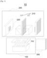
- Fig. 1 is a view illustrating a nucleic acid reaction detection device 10 according to an embodiment of the disclosure.
- the nucleic acid reaction detection device 10 comprises a sample reaction module 100 comprising a first reaction area and a second reaction area thermally independent from each other, an optical module 200 capable of detecting nucleic acid reaction of all samples in the sample reaction module, and one or more controllers 300 electrically connected with the sample reaction module and the optical module.
- the optical module is configured to be able to synchronously measure an optical signal of a first wavelength band from a sample in the first reaction area and an optical signal of a second wavelength band from a sample in the second reaction area, wherein the second wavelength band differs from the first wavelength band.
- the controller is configured to control the temperatures of the first reaction area and the second reaction area independently and control optical signal measurement of the sample in the first reaction area and optical signal measurement of the sample in the second reaction area independently.
- the nucleic acid reaction detection device 10 comprises the sample reaction module 100.
- the sample reaction module 100 is a module that receives samples which are to be analyzed and performs nucleic acid reaction.
- the sample reaction module 100 comprises a first reaction area 111 and a second reaction area 112. Each reaction area is thermally independent from another. A thermal insulation material or air gap may be provided between the first reaction area and the second reaction area to prevent heat transfer. According to an embodiment of the disclosure, the sample reaction module 100 comprises the first reaction area 111 and the second reaction area 112 thermally independent from each other. The sample reaction module 100 may comprise reaction areas 110 and heat transfer modules 120.
- the sample reaction module 100 may be configured so that each of the first reaction area 111 and the second reaction area 112 is able to receive at least two or more samples.
- the sample reaction module 100 comprises the reaction area 110 for receiving the sample or a reaction vessel including the sample.
- the reaction area 110 may comprise a plurality of receiving spaces 115.
- the receiving space 115 for receiving the sample may be a well for receiving the reaction vessel.
- Each reaction area may receive at least two or more samples using the plurality of receiving spaces 115.
- the number of the receiving spaces 115 included in each reaction area may be 2 to 96, 2 to 84, 2 to 72, 2 to 64, 2 to 56, 2 to 48, 2 to 40, or 2 to 32.
- the sample reaction module 100 adjusts the temperature of the received samples and performs nucleic acid reaction.
- the reaction area 110 may be formed of a metal or metal alloy with superior thermal conductivity.
- the reaction area 110 may be, e.g., a thermal block.
- the thermal block has a volume and is formed of a metal with superior thermal conductivity.
- the thermal block may have a well for receiving samples.
- a heat transfer module e.g., a Peltier element, may contact one surface of the thermal block to adjust the temperature.
- the heating plate may be formed of a plate for receiving samples and a thin metal sheet attached to the plate.
- the heating plate may be operated in such a manner that the plate is heated by applying electric current to the thin metal sheet.
- reaction area 110 may be formed of one or more chips or cartridges.
- An example of the cartridge is a fluid cartridge comprising a flow channel.
- the sample reaction module may further comprise the heat transfer module 120 for supplying heat to the reaction area 110 or absorbing heat from the reaction area 110.
- the heat transfer module 120 may switch the reaction area 110 into two or more temperatures.
- the heat transfer module 120 may be a device capable of heating and cooling both.
- the heat transfer module 120 may separately comprise a heat supplying means for supplying heat and a heat absorbing means for absorbing heat.
- the heat transfer module 120 may be a Peltier element capable of both heat supply and heat absorption to/from the reaction area 110 and positioned in the form of a plate on the bottom of the reaction area 110.
- the first reaction area and the second reaction area may be reaction areas 110 physically separated from each other.
- the nucleic acid reaction detection device according to the disclosure may comprise heat transfer modules 120 physically separated from each other to change the temperatures of the first reaction area and the second reaction area independently.
- the first reaction area 111 and the second reaction area 112 may be controlled thermally independently from each other.
- the reaction areas 111 and 112 may be controlled thermally independently from each other.
- the reaction areas being controlled thermally independently may mean that the temperature of each reaction area may be individually controlled. For example, while the first reaction area remains at 94 °C at a first time, the second reaction area may be cooled down from 94 °C to 60 °C or heated up from 60 °C to 75 °C or may remain at a specific temperature. By so doing, a separate nucleic acid reaction may be performed in each reaction area of the nucleic acid reaction detection device.
- the number of reaction areas included in the sample reaction module may range from 2 to 24, but is not limited thereto. For example, the number of reaction areas included in the sample reaction module may be 2, 3, 4, 5, 6, 8, 10, 12, 16, 20, or 24.
- the nucleic acid reaction detection device may comprise two or more reaction areas, four or more reaction areas, six or more reaction areas, or eight or more reaction areas. According to an embodiment, the nucleic acid reaction detection device may comprise 24 or less reaction areas, 20 or less reaction areas, 16 or less reaction areas, or 12 or less reaction areas. According to an embodiment of the disclosure, the sample reaction module may comprise other additional reaction area(s) than the first reaction area and the second reaction area. For example, the sample reaction module may further comprise a third reaction area and a fourth reaction area. The reaction areas each may be controlled thermally independently.
- the sample reaction module 100 may further comprise a pressure lid 130.
- the pressure lid 130 provides pressure to the reaction vessels containing samples positioned on the reaction area 110.
- the pressure lid 130 may contact the covers of the reaction vessels and press the covers of the reaction vessels, providing pressure to the reaction vessels.
- the pressure lid 130 may maintain a high temperature.
- the pressure lid 130 may comprise a heat plate (not shown) to maintain a temperature of 105 °C.
- the pressure lid 130 comprises a plurality of holes 131.
- the holes 131 of the pressure lid 130 are formed in the positions corresponding to the reaction vessels containing samples, positioned on the reaction area 110.
- the nucleic acid reaction detection device comprises the optical module 200 capable of detecting nucleic acid reaction of the samples in the sample reaction module.
- the optical module 200 radiates excitation lights to the samples in the sample reaction module 100 and senses the emission lights generated by the excitation lights, thereby detecting the nucleic acid reaction in the sample.
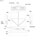
- the optical module 200 may comprise a light source 210 for illuminating the sample in the reaction area with an excitation light and a detector 220 for sensing an emission light received from the sample in the reaction area.
- the light source 210 illuminates the sample in the reaction area with an excitation light.
- the excitation light refers to the light generated from the light source 210 and reaching the sample positioned in the sample receiving space 115.
- the label in the sample may be excited by the excitation light.
- the excited label may emit an optical signal, e.g., fluorescent light.
- the light radiated from the light source 210 may also be referred to as an excitation light, and the light emitted from the label excited by the excitation light may also be referred to as an emission light.
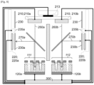
- the optical module 200 is configured so that, when a first light source 210a radiates light to the first reaction area 111, a second light source 210b may radiate light of a different wavelength band from that of the first light source 210a to the second reaction area 112.
- the optical module 200 may synchronously measure the optical signal of the first wavelength band generated from the sample in the first reaction area and the optical signal of the second wavelength band (which differs from the first wavelength band) generated from the sample in the second reaction area 112.
- at least two of the plurality of light sources 210 may radiate excitation lights of different wavelength bands from each other.
- the excitation lights of different wavelength bands may excite different labels.
- the excited label may emit an emission light, which is an optical signal, and the different labels emit emission lights of different wavelength band.
- emission light of a first wavelength band may excite a first label
- emission light of a second wavelength band may excite a second label.
- the number of the light sources 210 included in the optical module 200 is not particularly limited but, as an example, may be two or more or may be 100, 50, 40, 30, 20, 10 or less.
- the optical module 200 may comprise a light source wheel 213.
- the light source wheel 213 receives the plurality of light sources 210.
- the light source wheel 213 receives the light sources 210 may mean that the light sources 210 are attached or fixed to the light source wheel 213.
- the light source wheel 213 may be connected to a power transmission device, e.g., a motor, to rotate and may thus switch the light sources to illuminate each reaction area with light.
- the wavelength band of the excitation light radiated to the first reaction area 111 and the wavelength band of the excitation light radiated to the second reaction area, each, may be independently determined.
- a plurality of light sources may be configured to radiate excitation lights of different wavelength bands to the first reaction area, and another plurality of light sources may be separately configured to radiate excitation lights of different wavelength bands to the second reaction area.
- Fig. 2 and 4 a plurality of light sources may be configured to radiate excitation lights of different wavelength bands to the first reaction area, and another plurality of light sources may be separately configured to radiate excitation lights of different wavelength bands to the second reaction area.
- the sample reaction module 100 according to the disclosure may comprise two reaction areas 111 and 112, and the optical module 200 comprises two light source wheels 213 each comprising a plurality of light sources 210 to allow each wavelength band of excitation light radiated to each reaction area to be independently determined.
- the sample reaction module 100 according to the disclosure may comprise four reaction areas 111, 112, 113, and 114.
- the optical module 200 may comprise four light source wheels 213 each comprising a plurality of light sources 210 for the four reaction areas.
- the sample reaction module according to the disclosure may comprise four reaction areas.
- the optical module may comprise four light source wheels each comprising a plurality of light sources for the four reaction areas.
- the wavelength band of the excitation light radiated to the first reaction area and the wavelength band of the excitation light radiated to the second reaction area may be synchronously changed.
- a plurality of light sources capable of radiating excitation lights of different wavelength bands may be connected to a moving member, e.g., the light source wheel 213 to be individually positioned on two or more reaction areas.
- the light source wheel 213 comprises two light sources for radiating light of different wavelength bands
- the light sources may be positioned on the first reaction area 111 and the second reaction area 112 and may switch their positions (refer to Fig. 5A ).
- Fig. 5 Besides, as shown in Fig.
- the light source wheel 213 may comprise four light sources for radiating light of different wavelength bands and may synchronously radiate light of different wavelength bands to the first reaction area 111 and the second reaction area 112. In such a case, as the light source wheel 213 rotates, the light source 210a may be repositioned from the first reaction area 111 to the second reaction area 112, and another light source 210c may be positioned on the first reaction area 111.
- the light source wheel 213 may comprise four light sources for radiating light of different wavelength bands And the four light sources may be respectively positioned on different reaction areas 111, 112, 113, and 114 to synchronously radiate light of different wavelength bands to the four reaction areas.
- the light source 210a may be moved from the first reaction area 111 to the second reaction area 112
- the light source 210b may be moved from the second reaction area 112 to the third reaction area 113
- the light source 210c may be moved from the third reaction area 113 to the fourth reaction area 114
- the light source 210d may be moved from the fourth reaction area 114 to the first reaction area 111.
- such repositioning may be referred to as "cyclic movement.”
- Such configuration may economically adjust the number of light sources used as compared with the number of the reaction areas.
- the light source 210 comprises a light emitting element 211. There may be provided a plurality of light emitting elements 211.
- the light emitting element may be a light emitting diode (LED).
- the light emitting element may be a light emitting element that selectively radiates light of a wavelength band that is to be emitted from the light source 210.
- the light source 210 may comprise a filter 212.
- the filter 212 allows the reaction area to be illuminated with a light of a wavelength band intended by the light source 210.
- the filter 212 may be a filter that selectively transmits the light of the intended wavelength band among the lights generated from the light emitting element.
- the light source may comprise a plurality of filters, and the filters may be switched and used depending on the label used in the sample in the reaction area.
- the optical module 200 comprises a plurality of light sources. At least two light sources of the plurality of light sources may produce excitation lights of different wavelength bands. According to an embodiment of the disclosure, the optical module 200 may selectively radiate excitation lights of two or more wavelength bands.
- the optical module 200 may comprise a plurality of light sources 210.
- the optical module 200 may comprise two or more light sources 210 that radiate light of different wavelength bands.
- each of light sources may be configured by selecting a light emitting element 211 that generates light of a specific wavelength band for the each of light sources.
- the filter 212 of each light source may be selected and configured as a filter that selectively transmits light of a different wavelength band for each light source.
- the plurality of light sources 210 that radiate light of different wavelength bands may be fastened to the light source wheel 213, and the light source wheel 213 may move the light sources 210 to allow light of different wavelength bands to be sequentially radiated to the reaction areas 111 and 112.
- the optical module may selectively radiate excitation lights of different wavelength bands to one reaction area.
- the device according to the disclosure may detect a plurality of target nucleic acids that are detected by different labels in one sample.
- the sample reaction module is configured so that each of the first reaction area and the second reaction area are capable of receiving a plurality of samples.
- the optical module comprises a plurality of light sources, and one of the plurality of light sources simultaneously radiates excitation lights to the plurality of samples in one reaction area.
- the optical module may detect optical signals from a plurality of samples more quickly than when one light source detects optical signals while sequentially radiating excitation lights to a plurality of samples.
- the optical module 200 comprises a detector 220.
- the detector senses light. Specifically, the detector senses emission lights generated from samples.
- the detector may be, e.g., a CCD (Charge Coupled device), CMOS (Complementary Metal Oxide Semiconductor field effect transistor) or photodiode.
- one detector may sense all of the emission lights generated from all the reaction areas.
- one detector is configured to separately detect different wavelength bands of emission lights generated from the plurality of reaction areas.
- the optical module may comprise two or more detectors 220a and 220b as shown in Fig. 2 .
- each of the lights generated from the first reaction area 111 and the second reaction area 112 may be detected using an independent detector.
- the optical module comprises a plurality of detectors independently controlled, and one or more different detectors among the plurality of detectors may be assigned to each of the first reaction area and the second reaction area. Optical signals may be measured from the first sample set and second sample set by the one or more different detectors assigned.
- two or more detectors may be used in one reaction area.
- two or more detectors may sense emission lights from one reaction area, with the reaction area separated.
- the optical module is configured to be able to synchronously measure an optical signal of a first wavelength band from the sample in the first reaction area and an optical signal of a second wavelength band from the sample in the second reaction area, the second wavelength band different from the first wavelength band.
- the optical module may comprise a plurality of detectors 220a and 220b, and each of the plurality of detectors may be configured to sense the emission light generated from the sample positioned in a fixed and predetermined detection area 111 or 112 in the sample receiving module.
- the emission light refers to light that is generated from the sample and reaches the detector.
- the emission light is light that is generated by a signal-generating means, e.g., the label in the sample.
- the emission light corresponds to a signal or an optical signal.
- the optical module 200 may be configured so that each of the plurality of detectors senses the emission light generated from the sample positioned in the respectively predetermined detection area.
- the detection area means an area where one detector detects an emission light in the sample reaction module.
- the plurality of detectors each sense the emission light generated from the sample positioned in the predetermined detection area, this means that the detection area where each detector performs detection in the sample reaction module is previously determined.
- the samples positioned in the same detection area in the sample reaction module may be detected by the same detector, and the samples positioned in different detection areas may be detected by different detectors.
- the detection area for sensing emission lights may be fixed. For example, a first detector may detect only emission lights generated from a first detection area, which is a fixed area in the sample reaction module but may not detect emission lights generated from other area.
- one detection area may be included in one reaction area.
- the detection area may not be present over two or more reaction areas. It is preferable to measure the emission lights generated from different reaction areas by different detectors rather than measuring all of the lights synchronously generated from two or more reaction areas by one detector.
- a first detector 220a may be configured to detect only emission lights generated from the first reaction area 111, but not emission lights generated from other reaction area, e.g., the second reaction area 112.
- a second detector 220b may be configured to detect only emission lights generated from the second reaction area 112, but not emission lights generated from other area, e.g., the first reaction area 111.
- one reaction area may comprise one or more detection areas.
- the number of detectors in charge of one reaction area may be determined depending on the shape and size of the reaction area and detection schemes, and the number of detectors may be one or two or more.
- the optical module 200 may additionally comprise a filter 230 which may be positioned on an emission light path 270 to the detector.
- the filter may be a filter that selectively transmits the wavelength band of light, as the target for measurement, among the emission lights.
- the optical module may comprise a plurality of filters 230, and the filter positioned on the emission light path 270 may be replaced depending on the wavelength of the emission light to be measured. The replacement of the filter may be performed in such a manner that a plurality of filters 230 are attached to a filter wheel 235, and the filter wheel 235 is rotated as necessary.
- the optical module 200 may comprise a beam splitter 240.
- the beam splitter 240 reflects part of the excitation lights or emission lights, establishing an intended optical path.
- the excitation light generated from the light source 210 passes through the beam splitter 240 and reaches the sample received in the sample receiving space 115 of the reaction area 110, forming an excitation light path 260.
- the emission light emitted from the sample is reflected by the beam splitter 240 to the detector 220, forming an emission light path 270.
- the optical module 200 may comprise a light blocking means 250.
- the light blocking means 250 may be configured so that the excitation light radiated from, e.g., the first reaction area 111 is not radiated to the second reaction area 112 or other reaction area. Further, the light blocking means 250 may be configured so that, when the excitation light is radiated from the light source 210a to the first reaction area 111, other lights than the radiated excitation light are not radiated to the first reaction area 111.
- the light blocking means 250 may be disposed between the adjacent light sources. Alternatively, the light blocking means 250 may be disposed between the adjacent detectors. According to an embodiment, the light blocking means 250 may be shaped as a rectangular or circular tube. According to an embodiment, the light blocking means 250 may be shaped as a combination of a plurality of tubes.
- the nucleic acid reaction detection device comprises the controller 300.
- the controller may be, e.g., a computer, a micro-processor, or a programmable logic device.
- the controller 300 controls each of the temperatures of the first reaction area 111 and the second reaction area 112 independently. Specifically, the controller 300 may be electrically connected with the heat transfer module 120a of the first reaction area and control the direction and magnitude of the current applied to the heat transfer module 120a of the first reaction area 111, thereby controlling the temperature of the first reaction area 111. Further, the controller 300 is electrically connected with the heat transfer module 120b of the second reaction area 112 and control the direction, magnitude, and time of the current applied to the heat transfer module 120b of the second reaction area 112 independently from the control of the temperature of the first reaction area 111, thereby controlling the temperature of the second reaction area 112.
- the controller 300 receives the protocol for the first sample set positioned in the first reaction area, controls the temperature of the first reaction area 111 according to the protocol for the first sample set, receives the protocol for the second sample set positioned in the second reaction area, and controls the temperature of the second reaction area 112 according to the protocol for the second sample set.
- the controller 300 is configured to control the optical signal measurement on the sample in the first reaction area and the optical signal measurement on the sample in the second reaction area independently. Specifically, the controller 300 may move the light source wheel 213 to move the first light source 210a or second light source 210b to a predetermined position so that the light of wavelength band capable of generating an optical signal from the sample in the first reaction area may be radiated to the first reaction area. Further, the controller 300 may supply current to the light source 210a so that the light source 210a is able to radiate the excitation light 260a to the sample.
- the controller 300 may move the filter wheel 235a to position the filter 230a, which is able to selectively transmit the emission light 270a, on the emission light path 270a and supply current to the detector 220a so that the detector 220a is able to sense the emission light 270a generated from the sample by the excitation light 260a radiated from the light source 210a.
- the controller may move the light source wheel 213 and the filter wheel 230b and supply current to the light source 210b and the detector 220b as described above.
- the controller 300 may operate the sample reaction module 100 and the optical module 200 of the nucleic acid reaction detection device so that the temperature control and optical signal measurement on each reaction area are performed in the order determined by the protocol.
- the controller 300 may receive the protocol for each sample and according to the received protocol independently control the temperature of each reaction area of the sample reaction module and independently control the optical signal measurement on each reaction area of the optical module. For example, the controller 300 may operate the device to selectively perform optical signal measurement only on the sample in the first reaction area without measuring the optical signal for the sample in the second reaction area. Alternatively, the controller 300 may operate the device to selectively perform optical signal measurement only on the sample in the second reaction area without measuring the optical signal for the sample in the first reaction area. Or, the controller 300 may operate the device to synchronously perform optical signal measurement on the samples in the first reaction area and the second reaction area.
- the controller may receive distinct protocols for the first reaction area and the second reaction area, control temperatures of the first reaction area and the second reaction area according to the received protocols independently, and operate the nucleic acid reaction detection device to perform an operation comprising at least one of the steps of, based on the received protocols for all the reaction areas:
- Reaction is performed on the sample positioned in the first reaction area and the sample positioned in the second reaction area by protocols independent from each other, and the first reaction area and the second reaction area may individually or simultaneously reach the light detection time.
- the controller 300 When it becomes time to detecting optical signal only for one of the first reaction area and the second reaction area, the controller 300 operates to perform the operation of measuring the optical signal for the sample in one reaction area of the first reaction area and the second reaction area without measuring the optical signal for the sample in the other reaction area. Further, when it becomes time to detecting optical signals for both the first reaction area and the second reaction area, the controller 300 operates to perform the operation of measuring the optical signal for the sample in each reaction area. At this time, the wavelength bands of the optical signals measured from the first reaction area and the second reaction area may differ from each other.
- the controller may be configured to control the sample reaction module and optical module to be able to selectively perform optical signal measurement on one area of the first reaction area and the second reaction area under the condition where the temperatures of the first reaction area and the second reaction area differ from each other.
- the controller 300 may control the light source 210a, filter wheel 230a, and detector 220a for the first reaction area to measure the optical signal for the first reaction area while simultaneously controlling the heat transfer module 120 of the second reaction area 112 to allow a nucleic acid reaction to occur in the second reaction area.
- the controller may operate the device to be able to detect a plurality of target nucleic acids in one sample. Specifically, the controller may allow optical signals of two or more different wavelength bands to be measured sequentially for one reaction area. According to an embodiment of the disclosure, the controller may be configured to control the sample reaction module and optical module to be able to sequentially measure optical signals of two or more different wavelength bands for one area of the first reaction area and the second reaction area under the condition where the temperatures of the first reaction area and the second reaction area differ from each other.
- the controller may move the first light source 210a to the position where the excitation light may be radiated to the first reaction area 111 and applies current to allow the first light source 210a to radiate an excitation light. Then, the controller may drive the filter wheel 235a to position the filter, which is able to selectively transmit the emission light generated from the sample by the excitation light from the first light source 210a, on the excitation light path 270a and apply current to the detector 220a, thereby measuring the optical signal from the first reaction area 111.
- the controller drives the light source wheel 213 to move the second light source 210b to the position where it may radiate the excitation light to the first reaction area 111 at a second time and applies current to allow the second light source 210b to radiate the excitation light. Then, the controller may drive the filter wheel 235a to position the filter, which is able to measure the emission light generated from the sample by the excitation light from the second light source 210b, on the excitation light path 270a and apply current to the detector 220a, thereby measuring the optical signal from the first reaction area 111. While the above-described optical signal measurement is carried out on the first reaction area 111, the controller 300 may change the temperature of the second reaction area 112 and perform nucleic acid reaction.
- the nucleic acid reaction detection device 10 may detect each of a plurality of targets for each of a plurality of sample sets where optical signal detection on the plurality of targets and nucleic acid reaction are performed according to different protocols.
Landscapes
- Chemical & Material Sciences (AREA)
- Health & Medical Sciences (AREA)
- Life Sciences & Earth Sciences (AREA)
- General Health & Medical Sciences (AREA)
- Immunology (AREA)
- Physics & Mathematics (AREA)
- Analytical Chemistry (AREA)
- Biochemistry (AREA)
- Chemical Kinetics & Catalysis (AREA)
- General Physics & Mathematics (AREA)
- Pathology (AREA)
- Organic Chemistry (AREA)
- Nuclear Medicine, Radiotherapy & Molecular Imaging (AREA)
- Proteomics, Peptides & Aminoacids (AREA)
- Engineering & Computer Science (AREA)
- Zoology (AREA)
- Wood Science & Technology (AREA)
- Molecular Biology (AREA)
- Bioinformatics & Cheminformatics (AREA)
- Microbiology (AREA)
- Biotechnology (AREA)
- Biophysics (AREA)
- General Engineering & Computer Science (AREA)
- Genetics & Genomics (AREA)
- Clinical Laboratory Science (AREA)
- Optics & Photonics (AREA)
- Hematology (AREA)
- Apparatus Associated With Microorganisms And Enzymes (AREA)
- Measuring Or Testing Involving Enzymes Or Micro-Organisms (AREA)
- Investigating, Analyzing Materials By Fluorescence Or Luminescence (AREA)
- Investigating Or Analysing Materials By The Use Of Chemical Reactions (AREA)
Claims (12)
- Procédé de détection d'un acide nucléique cible dans un échantillon, le procédé comprenant les étapes suivantes :(a) le positionnement d'un premier ensemble d'échantillons dans une première zone (111) de réaction d'un dispositif (10) de détection de réaction d'acide nucléique et d'un deuxième ensemble d'échantillons dans une deuxième zone (112) de réaction du dispositif (10) de détection de réaction d'acide nucléique et la mise en oeuvre d'une réaction d'acide nucléique ; dans lequel le dispositif de détection de réaction d'acide nucléique comprend un module (100) de réaction d'échantillon comprenant la première zone (111) de réaction et la deuxième zone (112) de réaction thermiquement indépendantes l'une de l'autre, un module optique (200) pour détecter une réaction d'acide nucléique d'échantillons dans la première zone de réaction et la deuxième zone de réaction, et un dispositif de commande (300) ; dans lequel les températures de la première zone de réaction et de la deuxième zone de réaction sont régulées conformément à des protocoles différents ; dans lequel le module de réaction d'échantillon est configuré de sorte que chacune parmi la première zone de réaction et la deuxième zone de réaction est capable de recevoir une pluralité d'échantillons ; et dans lequel le module optique comprend une pluralité de sources de lumière (210, 210a, 210b, 210c, 210d), et une de la pluralité de sources de lumière irradie simultanément une lumière d'excitation sur la pluralité d'échantillons dans une zone de réaction ;(b) la mesure de signaux optiques provenant du premier ensemble d'échantillons et du deuxième ensemble d'échantillons ; dans lequel les signaux optiques provenant du premier ensemble d'échantillons et du deuxième ensemble d'échantillons sont mesurés de manière synchrone ; dans lequel les bandes de longueur d'onde des signaux optiques mesurés de manière synchrone à partir du premier ensemble d'échantillons et du deuxième ensemble d'échantillons sont différentes les unes des autres ; et(c) la détection d'un acide nucléique cible dans un échantillon inclus dans le premier ensemble d'échantillons et le deuxième ensemble d'échantillons en analysant les signaux optiques mesurés.
- Procédé selon la revendication 1, dans lequel l'étape de mesure des signaux optiques comprend en outre une étape de mesure d'un signal optique provenant de l'un parmi le premier ensemble d'échantillons et le deuxième ensemble d'échantillons sans mesurer un signal optique provenant de l'autre parmi le premier ensemble d'échantillons et le deuxième ensemble d'échantillons.
- Procédé selon la revendication 1, dans lequel la mesure d'un signal optique pour le premier ensemble d'échantillons est effectuée en mesurant séquentiellement des signaux optiques de deux bandes de longueurs d'onde différentes ou plus pour le premier ensemble d'échantillons.
- Procédé selon la revendication 1, dans lequel le premier ensemble d'échantillons comprend une pluralité d'échantillons, et dans lequel la mesure d'un signal optique provenant du premier ensemble d'échantillons positionné dans la première zone de réaction mesure simultanément des signaux optiques provenant de deux échantillons ou plus inclus dans le premier ensemble d'échantillons.
- Procédé selon la revendication 1, dans lequel le dispositif de commande fait fonctionner le dispositif de détection de réaction d'acide nucléique pour effectuer une opération comprenant en outre une étape suivante :
la mesure d'un signal optique pour un ensemble d'échantillons du premier ensemble d'échantillons et du deuxième ensemble d'échantillons sans mesurer un signal optique pour l'autre ensemble d'échantillons. - Procédé selon la revendication 1, dans lequel au moins deux de la pluralité de sources de lumière produisent des lumières d'excitation de bandes de longueur d'onde différentes les unes des autres.
- Procédé selon la revendication 1, dans lequel le module optique (200) comprend une pluralité de détecteurs (220, 220a, 200b), et dans lequel chacun de la pluralité de détecteurs détecte une lumière émise par un échantillon dans une zone prédéterminée et fixe du module de réaction d'échantillon.
- Procédé selon la revendication 1, dans lequel le module optique (200) comprend une pluralité de détecteurs (220, 220a, 200b) commandés indépendamment, dans lequel un ou plusieurs détecteurs différents parmi la pluralité de détecteurs sont attribués à chacune parmi la première zone (111) de réaction et la deuxième zone (112) de réaction, et dans lequel des signaux optiques sont détectés à partir du premier ensemble d'échantillons et du deuxième ensemble d'échantillons par les un ou plusieurs détecteurs différents attribués respectivement.
- Dispositif (10) de détection de réaction d'acide nucléique, comprenant :un module (100) de réaction d'échantillon comprenant une première zone (111) de réaction et une deuxième zone (112) de réaction thermiquement indépendantes l'une de l'autre ;un module optique (200) pour détecter une réaction d'acide nucléique d'échantillons dans le module de réaction d'échantillons ; etun ou plusieurs dispositifs de commande (300) connectés électriquement au module de réaction d'échantillon et au module optique, dans lequelle module optique est configuré pour mesurer de manière synchrone un signal optique d'une première bande de longueur d'onde provenant d'un échantillon dans la première zone de réaction et un signal optique d'une deuxième bande de longueur d'onde provenant d'un échantillon dans la deuxième zone de réaction, dans lequel la deuxième bande de longueur d'onde est différente de la première bande de longueur d'onde,dans lequel le module de réaction d'échantillon est configuré de sorte que chacune parmi la première zone de réaction et la deuxième zone de réaction est capable de recevoir une pluralité d'échantillons ;dans lequel le module optique comprend une pluralité de sources de lumière (210, 210a, 210b, 210c, 210d), etune de la pluralité de sources de lumière irradie simultanément une lumière d'excitation sur la pluralité d'échantillons dans une zone de réaction ;et dans lequel le dispositif de commande est configuré pour réguler les températures de la première zone de réaction et de la deuxième zone de réaction de manière indépendante et commander la mesure de signal optique d'un échantillon dans la première zone de réaction et la mesure de signal optique d'un échantillon dans la deuxième zone de réaction de manière indépendante.
- Dispositif de détection de réaction d'acide nucléique selon la revendication 9, dans lequel le dispositif de commande reçoit des protocoles distincts pour la première zone de réaction et la deuxième zone de réaction ; régule les températures de la première zone de réaction et de la deuxième zone de réaction de manière indépendante conformément aux protocoles reçus ; et fait fonctionner le dispositif de détection de réaction d'acide nucléique pour effectuer une opération comprenant au moins l'une des étapes suivantes, sur la base des protocoles reçus pour toutes les zones de réaction :(i) la mesure d'un signal optique pour un échantillon dans une zone de réaction parmi la première zone de réaction et la deuxième zone de réaction sans mesurer un signal optique pour un échantillon dans l'autre zone de réaction ; et(ii) la mesure de manière synchrone d'un signal optique d'une première bande de longueur d'onde provenant d'un échantillon dans la première zone de réaction et d'un signal optique d'une deuxième bande de longueur d'onde provenant d'un échantillon dans la deuxième zone de réaction, dans lequel la deuxième bande de longueur d'onde est différente de la première bande de longueur d'onde.
- Dispositif de détection de réaction d'acide nucléique selon la revendication 9, dans lequel le module optique (200) comprend une pluralité de détecteurs (200, 200a, 200b), et dans lequel chacun de la pluralité de détecteurs détecte une lumière émise par un échantillon dans une zone prédéterminée et fixe de la réaction d'échantillon (100).
- Dispositif de détection de réaction d'acide nucléique selon la revendication 9, dans lequel au moins deux de la pluralité de sources de lumière (210, 210a, 210b, 210c, 210d) produisent des lumières d'excitation de bandes de longueurs d'onde différentes les unes des autres.
Applications Claiming Priority (4)
| Application Number | Priority Date | Filing Date | Title |
|---|---|---|---|
| KR20190064472 | 2019-05-31 | ||
| KR20190078284 | 2019-06-28 | ||
| KR20190162094 | 2019-12-06 | ||
| PCT/KR2020/007040 WO2020242261A1 (fr) | 2019-05-31 | 2020-05-29 | Procédé de détection d'acide nucléique cible dans un échantillon |
Publications (3)
| Publication Number | Publication Date |
|---|---|
| EP3976261A1 EP3976261A1 (fr) | 2022-04-06 |
| EP3976261A4 EP3976261A4 (fr) | 2023-01-25 |
| EP3976261B1 true EP3976261B1 (fr) | 2024-12-25 |
Family
ID=73552406
Family Applications (2)
| Application Number | Title | Priority Date | Filing Date |
|---|---|---|---|
| EP20812734.0A Active EP3976261B1 (fr) | 2019-05-31 | 2020-05-29 | Procédé de détection d'un acide nucléique cible dans un échantillon et dispositif de détection d'une réaction d'acide nucléique |
| EP20812735.7A Active EP3977101B1 (fr) | 2019-05-31 | 2020-05-29 | Dispositif et procédé de détection de lumière |
Family Applications After (1)
| Application Number | Title | Priority Date | Filing Date |
|---|---|---|---|
| EP20812735.7A Active EP3977101B1 (fr) | 2019-05-31 | 2020-05-29 | Dispositif et procédé de détection de lumière |
Country Status (4)
| Country | Link |
|---|---|
| US (2) | US12571734B2 (fr) |
| EP (2) | EP3976261B1 (fr) |
| KR (3) | KR102943394B1 (fr) |
| WO (2) | WO2020242261A1 (fr) |
Families Citing this family (1)
| Publication number | Priority date | Publication date | Assignee | Title |
|---|---|---|---|---|
| WO2025122819A1 (fr) * | 2023-12-08 | 2025-06-12 | Sensill, Inc. | Dispositifs, procédés et systèmes de mesure et d'enregistrement d'une matrice de réactifs |
Family Cites Families (29)
| Publication number | Priority date | Publication date | Assignee | Title |
|---|---|---|---|---|
| US4683195A (en) | 1986-01-30 | 1987-07-28 | Cetus Corporation | Process for amplifying, detecting, and/or-cloning nucleic acid sequences |
| US4683202A (en) | 1985-03-28 | 1987-07-28 | Cetus Corporation | Process for amplifying nucleic acid sequences |
| US4800159A (en) | 1986-02-07 | 1989-01-24 | Cetus Corporation | Process for amplifying, detecting, and/or cloning nucleic acid sequences |
| EP0953838A1 (fr) * | 1998-05-01 | 1999-11-03 | F. Hoffmann-La Roche Ag | Appareil pour la surveillance simultanée de réactions ayant lieu dans une pluralité de récipients de réaction |
| JP2003344290A (ja) | 2002-05-27 | 2003-12-03 | Aisin Cosmos R & D Co Ltd | 温度調節付蛍光検出装置 |
| US7148043B2 (en) | 2003-05-08 | 2006-12-12 | Bio-Rad Laboratories, Inc. | Systems and methods for fluorescence detection with a movable detection module |
| EP1962084A1 (fr) | 2007-02-21 | 2008-08-27 | Roche Diagnostics GmbH | Appareil d'émission et de détection de faisceaux lumineux |
| CA2754884C (fr) * | 2007-06-21 | 2013-04-30 | Gen-Probe Incorporated | Methodes pour concentrer un analyte |
| WO2010104478A1 (fr) | 2009-03-10 | 2010-09-16 | Agency For Science, Technology And Research | Appareil pour le traitement d'un échantillon biologique et/ou chimique |
| CN104404134B (zh) * | 2009-04-03 | 2017-05-10 | 莱弗斯基因股份有限公司 | 多重核酸检测方法和系统 |
| KR20120012468A (ko) * | 2009-04-15 | 2012-02-10 | 비오까르띠 에스아 | rtPCR 반응을 모니터링하기 위한 광학 검출 시스템 |
| US20110124111A1 (en) | 2009-08-31 | 2011-05-26 | Life Technologies Corporation | Low-volume sequencing system and method of use |
| JP5470007B2 (ja) | 2009-11-25 | 2014-04-16 | 株式会社日立ハイテクノロジーズ | 測定装置および全反射蛍光測定装置 |
| KR20120116778A (ko) * | 2011-04-13 | 2012-10-23 | 삼성테크윈 주식회사 | 바이오 진단장치 |
| CN102329725A (zh) | 2010-06-16 | 2012-01-25 | 三星泰科威株式会社 | 光透射温度控制装置、生物诊断设备和方法 |
| EP2669376B1 (fr) * | 2011-01-26 | 2017-08-16 | Olympus Corporation | Procédé pour identifier le polymorphisme d'une molécule d'acide nucléique |
| JP6088487B2 (ja) | 2011-04-15 | 2017-03-01 | ベクトン・ディキンソン・アンド・カンパニーBecton, Dickinson And Company | 走査リアルタイムマイクロ流体熱サイクラーと同期熱サイクリング及び走査光学検出の方法 |
| KR20120139206A (ko) * | 2011-06-17 | 2012-12-27 | 나노바이오시스 주식회사 | 박막형 열 블록 및 박막형 pcr 칩을 포함하는 휴대용 실시간 pcr 장치 |
| KR20130071645A (ko) | 2011-12-21 | 2013-07-01 | 케이맥(주) | 독립적으로 온도제어 가능한 다중 실험 장치 |
| JP6281564B2 (ja) * | 2013-03-29 | 2018-02-21 | ソニー株式会社 | データ処理装置、光学検出システム、データ処理方法及びデータ処理プログラム |
| US10006861B2 (en) * | 2013-06-28 | 2018-06-26 | Streck, Inc. | Devices for real-time polymerase chain reaction |
| KR102126032B1 (ko) | 2013-07-31 | 2020-07-08 | 삼성전자주식회사 | 다채널 형광 검출 모듈 및 이를 포함하는 핵산 분석 시스템 |
| JP6261945B2 (ja) | 2013-10-29 | 2018-01-17 | 東芝メディカルシステムズ株式会社 | 自動分析装置 |
| KR101618113B1 (ko) * | 2014-02-10 | 2016-05-09 | 나노바이오시스 주식회사 | 일 방향 슬라이딩 구동 수단을 구비하는 pcr 장치 및 이를 이용하는 pcr 방법 |
| WO2015176253A1 (fr) * | 2014-05-21 | 2015-11-26 | Coyote Bioscience Co., Ltd. | Systèmes et procédés pour le cyclage thermique à faible puissance |
| EP3168287A4 (fr) * | 2014-07-08 | 2018-01-24 | National Institute of Advanced Industrial Science and Technology | Dispositif ainsi que procédé d'amplification d'acide nucléique, et puce pour amplification d'acide nucléique |
| US20170114398A1 (en) * | 2015-10-27 | 2017-04-27 | Alveo Technologies, Inc. | Systems, methods and devices for detection of nucleic acids |
| US20180258465A1 (en) | 2017-03-11 | 2018-09-13 | Yan Wang | Methods and Devices for Performing Real Time Digital PCR |
| CN207742096U (zh) * | 2018-02-07 | 2018-08-17 | 张哲夫 | 一种多通道荧光定量pcr仪的光学系统 |
-
2020
- 2020-05-29 KR KR1020217042113A patent/KR102943394B1/ko active Active
- 2020-05-29 EP EP20812734.0A patent/EP3976261B1/fr active Active
- 2020-05-29 WO PCT/KR2020/007040 patent/WO2020242261A1/fr not_active Ceased
- 2020-05-29 WO PCT/KR2020/007044 patent/WO2020242263A1/fr not_active Ceased
- 2020-05-29 EP EP20812735.7A patent/EP3977101B1/fr active Active
- 2020-05-29 US US17/614,740 patent/US12571734B2/en active Active
- 2020-05-29 KR KR1020257029610A patent/KR20250135914A/ko active Pending
- 2020-05-29 KR KR1020217042916A patent/KR102857782B1/ko active Active
- 2020-05-29 US US17/614,827 patent/US20220244181A1/en active Pending
Also Published As
| Publication number | Publication date |
|---|---|
| EP3976261A1 (fr) | 2022-04-06 |
| EP3977101A4 (fr) | 2023-01-18 |
| WO2020242263A1 (fr) | 2020-12-03 |
| KR20220003138A (ko) | 2022-01-07 |
| US20220228988A1 (en) | 2022-07-21 |
| US20220244181A1 (en) | 2022-08-04 |
| KR20250135914A (ko) | 2025-09-15 |
| KR102943394B1 (ko) | 2026-03-24 |
| KR20220000907A (ko) | 2022-01-04 |
| US12571734B2 (en) | 2026-03-10 |
| KR102857782B1 (ko) | 2025-09-12 |
| EP3977101A1 (fr) | 2022-04-06 |
| EP3977101B1 (fr) | 2025-06-25 |
| EP3976261A4 (fr) | 2023-01-25 |
| WO2020242261A1 (fr) | 2020-12-03 |
Similar Documents
| Publication | Publication Date | Title |
|---|---|---|
| US11633739B2 (en) | Droplet-based assay system | |
| EP1288314B1 (fr) | Quantification en temps réel avec des étalons internes | |
| US9417190B2 (en) | Calibrations and controls for droplet-based assays | |
| CA3149293C (fr) | Systeme de dosage base sur des gouttelettes | |
| JP4458133B2 (ja) | 核酸増幅装置 | |
| US20090227007A1 (en) | Devices and methods for monitoring genomic dna of organisms | |
| US20120183965A1 (en) | Nucleic acid detection | |
| JP2014511178A (ja) | 核酸の定量的かつ高度に多重化された検出 | |
| EP3976261B1 (fr) | Procédé de détection d'un acide nucléique cible dans un échantillon et dispositif de détection d'une réaction d'acide nucléique | |
| US20060040303A1 (en) | Reaction mixture for positioning a reaction vessel relative to a detection unit | |
| US20230372935A1 (en) | Partition-based method of analysis | |
| WO2018031687A1 (fr) | Appareil de détection de signaux fluorescents émis par des échantillons | |
| US20260043742A1 (en) | Nucleic acid amplification process controls | |
| US20240310282A1 (en) | Apparatus for detecting optical signals | |
| US20240142376A1 (en) | Light detection module and apparatus for detecting target analyte comprising the same | |
| EP4455304A1 (fr) | Commandes de processus d'amplification d'acide nucléique | |
| JP2026071210A (ja) | 核酸増幅プロセスの制御 | |
| JP2026071211A (ja) | 核酸増幅プロセスの制御 | |
| KR20230046616A (ko) | Tir 렌즈를 포함하는 타깃 분석물 검출장치 |
Legal Events
| Date | Code | Title | Description |
|---|---|---|---|
| STAA | Information on the status of an ep patent application or granted ep patent |
Free format text: STATUS: THE INTERNATIONAL PUBLICATION HAS BEEN MADE |
|
| PUAI | Public reference made under article 153(3) epc to a published international application that has entered the european phase |
Free format text: ORIGINAL CODE: 0009012 |
|
| STAA | Information on the status of an ep patent application or granted ep patent |
Free format text: STATUS: REQUEST FOR EXAMINATION WAS MADE |
|
| 17P | Request for examination filed |
Effective date: 20211227 |
|
| AK | Designated contracting states |
Kind code of ref document: A1 Designated state(s): AL AT BE BG CH CY CZ DE DK EE ES FI FR GB GR HR HU IE IS IT LI LT LU LV MC MK MT NL NO PL PT RO RS SE SI SK SM TR |
|
| DAV | Request for validation of the european patent (deleted) | ||
| DAX | Request for extension of the european patent (deleted) | ||
| A4 | Supplementary search report drawn up and despatched |
Effective date: 20230102 |
|
| RIC1 | Information provided on ipc code assigned before grant |
Ipc: B01L 7/00 20060101ALI20221220BHEP Ipc: B01L 3/00 20060101ALI20221220BHEP Ipc: C12Q 1/686 20180101ALI20221220BHEP Ipc: C12Q 1/6816 20180101ALI20221220BHEP Ipc: G01N 21/64 20060101AFI20221220BHEP |
|
| REG | Reference to a national code |
Ref country code: DE Ref legal event code: R079 Ref document number: 602020043766 Country of ref document: DE Free format text: PREVIOUS MAIN CLASS: B01L0007000000 Ipc: G01N0021640000 |
|
| GRAP | Despatch of communication of intention to grant a patent |
Free format text: ORIGINAL CODE: EPIDOSNIGR1 |
|
| STAA | Information on the status of an ep patent application or granted ep patent |
Free format text: STATUS: GRANT OF PATENT IS INTENDED |
|
| RIC1 | Information provided on ipc code assigned before grant |
Ipc: B01L 3/00 20060101ALI20240702BHEP Ipc: C12Q 1/686 20180101ALI20240702BHEP Ipc: C12Q 1/6816 20180101ALI20240702BHEP Ipc: G01N 21/64 20060101AFI20240702BHEP |
|
| INTG | Intention to grant announced |
Effective date: 20240715 |
|
| GRAS | Grant fee paid |
Free format text: ORIGINAL CODE: EPIDOSNIGR3 |
|
| GRAA | (expected) grant |
Free format text: ORIGINAL CODE: 0009210 |
|
| STAA | Information on the status of an ep patent application or granted ep patent |
Free format text: STATUS: THE PATENT HAS BEEN GRANTED |
|
| AK | Designated contracting states |
Kind code of ref document: B1 Designated state(s): AL AT BE BG CH CY CZ DE DK EE ES FI FR GB GR HR HU IE IS IT LI LT LU LV MC MK MT NL NO PL PT RO RS SE SI SK SM TR |
|
| REG | Reference to a national code |
Ref country code: GB Ref legal event code: FG4D |
|
| REG | Reference to a national code |
Ref country code: CH Ref legal event code: EP |
|
| REG | Reference to a national code |
Ref country code: DE Ref legal event code: R096 Ref document number: 602020043766 Country of ref document: DE |
|
| REG | Reference to a national code |
Ref country code: IE Ref legal event code: FG4D |
|
| REG | Reference to a national code |
Ref country code: LT Ref legal event code: MG9D |
|
| PG25 | Lapsed in a contracting state [announced via postgrant information from national office to epo] |
Ref country code: HR Free format text: LAPSE BECAUSE OF FAILURE TO SUBMIT A TRANSLATION OF THE DESCRIPTION OR TO PAY THE FEE WITHIN THE PRESCRIBED TIME-LIMIT Effective date: 20241225 |
|
| PG25 | Lapsed in a contracting state [announced via postgrant information from national office to epo] |
Ref country code: FI Free format text: LAPSE BECAUSE OF FAILURE TO SUBMIT A TRANSLATION OF THE DESCRIPTION OR TO PAY THE FEE WITHIN THE PRESCRIBED TIME-LIMIT Effective date: 20241225 |
|
| PG25 | Lapsed in a contracting state [announced via postgrant information from national office to epo] |
Ref country code: BG Free format text: LAPSE BECAUSE OF FAILURE TO SUBMIT A TRANSLATION OF THE DESCRIPTION OR TO PAY THE FEE WITHIN THE PRESCRIBED TIME-LIMIT Effective date: 20241225 |
|
| PG25 | Lapsed in a contracting state [announced via postgrant information from national office to epo] |
Ref country code: NO Free format text: LAPSE BECAUSE OF FAILURE TO SUBMIT A TRANSLATION OF THE DESCRIPTION OR TO PAY THE FEE WITHIN THE PRESCRIBED TIME-LIMIT Effective date: 20250325 |
|
| PG25 | Lapsed in a contracting state [announced via postgrant information from national office to epo] |
Ref country code: GR Free format text: LAPSE BECAUSE OF FAILURE TO SUBMIT A TRANSLATION OF THE DESCRIPTION OR TO PAY THE FEE WITHIN THE PRESCRIBED TIME-LIMIT Effective date: 20250326 Ref country code: LV Free format text: LAPSE BECAUSE OF FAILURE TO SUBMIT A TRANSLATION OF THE DESCRIPTION OR TO PAY THE FEE WITHIN THE PRESCRIBED TIME-LIMIT Effective date: 20241225 |
|
| PG25 | Lapsed in a contracting state [announced via postgrant information from national office to epo] |
Ref country code: RS Free format text: LAPSE BECAUSE OF FAILURE TO SUBMIT A TRANSLATION OF THE DESCRIPTION OR TO PAY THE FEE WITHIN THE PRESCRIBED TIME-LIMIT Effective date: 20250325 |
|
| REG | Reference to a national code |
Ref country code: NL Ref legal event code: MP Effective date: 20241225 |
|
| PG25 | Lapsed in a contracting state [announced via postgrant information from national office to epo] |
Ref country code: NL Free format text: LAPSE BECAUSE OF FAILURE TO SUBMIT A TRANSLATION OF THE DESCRIPTION OR TO PAY THE FEE WITHIN THE PRESCRIBED TIME-LIMIT Effective date: 20241225 |
|
| REG | Reference to a national code |
Ref country code: AT Ref legal event code: MK05 Ref document number: 1754550 Country of ref document: AT Kind code of ref document: T Effective date: 20241225 |
|
| PG25 | Lapsed in a contracting state [announced via postgrant information from national office to epo] |
Ref country code: SM Free format text: LAPSE BECAUSE OF FAILURE TO SUBMIT A TRANSLATION OF THE DESCRIPTION OR TO PAY THE FEE WITHIN THE PRESCRIBED TIME-LIMIT Effective date: 20241225 |
|
| PG25 | Lapsed in a contracting state [announced via postgrant information from national office to epo] |
Ref country code: PL Free format text: LAPSE BECAUSE OF FAILURE TO SUBMIT A TRANSLATION OF THE DESCRIPTION OR TO PAY THE FEE WITHIN THE PRESCRIBED TIME-LIMIT Effective date: 20241225 |
|
| PGFP | Annual fee paid to national office [announced via postgrant information from national office to epo] |
Ref country code: DE Payment date: 20250320 Year of fee payment: 6 |
|
| PG25 | Lapsed in a contracting state [announced via postgrant information from national office to epo] |
Ref country code: ES Free format text: LAPSE BECAUSE OF FAILURE TO SUBMIT A TRANSLATION OF THE DESCRIPTION OR TO PAY THE FEE WITHIN THE PRESCRIBED TIME-LIMIT Effective date: 20241225 |
|
| PG25 | Lapsed in a contracting state [announced via postgrant information from national office to epo] |
Ref country code: IS Free format text: LAPSE BECAUSE OF FAILURE TO SUBMIT A TRANSLATION OF THE DESCRIPTION OR TO PAY THE FEE WITHIN THE PRESCRIBED TIME-LIMIT Effective date: 20250425 |
|
| PG25 | Lapsed in a contracting state [announced via postgrant information from national office to epo] |
Ref country code: PT Free format text: LAPSE BECAUSE OF FAILURE TO SUBMIT A TRANSLATION OF THE DESCRIPTION OR TO PAY THE FEE WITHIN THE PRESCRIBED TIME-LIMIT Effective date: 20250428 |
|
| PG25 | Lapsed in a contracting state [announced via postgrant information from national office to epo] |
Ref country code: EE Free format text: LAPSE BECAUSE OF FAILURE TO SUBMIT A TRANSLATION OF THE DESCRIPTION OR TO PAY THE FEE WITHIN THE PRESCRIBED TIME-LIMIT Effective date: 20241225 |
|
| PG25 | Lapsed in a contracting state [announced via postgrant information from national office to epo] |
Ref country code: RO Free format text: LAPSE BECAUSE OF FAILURE TO SUBMIT A TRANSLATION OF THE DESCRIPTION OR TO PAY THE FEE WITHIN THE PRESCRIBED TIME-LIMIT Effective date: 20241225 Ref country code: AT Free format text: LAPSE BECAUSE OF FAILURE TO SUBMIT A TRANSLATION OF THE DESCRIPTION OR TO PAY THE FEE WITHIN THE PRESCRIBED TIME-LIMIT Effective date: 20241225 |
|
| PG25 | Lapsed in a contracting state [announced via postgrant information from national office to epo] |
Ref country code: SK Free format text: LAPSE BECAUSE OF FAILURE TO SUBMIT A TRANSLATION OF THE DESCRIPTION OR TO PAY THE FEE WITHIN THE PRESCRIBED TIME-LIMIT Effective date: 20241225 |
|
| PG25 | Lapsed in a contracting state [announced via postgrant information from national office to epo] |
Ref country code: CZ Free format text: LAPSE BECAUSE OF FAILURE TO SUBMIT A TRANSLATION OF THE DESCRIPTION OR TO PAY THE FEE WITHIN THE PRESCRIBED TIME-LIMIT Effective date: 20241225 |
|
| PG25 | Lapsed in a contracting state [announced via postgrant information from national office to epo] |
Ref country code: IT Free format text: LAPSE BECAUSE OF FAILURE TO SUBMIT A TRANSLATION OF THE DESCRIPTION OR TO PAY THE FEE WITHIN THE PRESCRIBED TIME-LIMIT Effective date: 20241225 |
|
| PG25 | Lapsed in a contracting state [announced via postgrant information from national office to epo] |
Ref country code: SE Free format text: LAPSE BECAUSE OF FAILURE TO SUBMIT A TRANSLATION OF THE DESCRIPTION OR TO PAY THE FEE WITHIN THE PRESCRIBED TIME-LIMIT Effective date: 20241225 |
|
| REG | Reference to a national code |
Ref country code: DE Ref legal event code: R097 Ref document number: 602020043766 Country of ref document: DE |
|
| PG25 | Lapsed in a contracting state [announced via postgrant information from national office to epo] |
Ref country code: DK Free format text: LAPSE BECAUSE OF FAILURE TO SUBMIT A TRANSLATION OF THE DESCRIPTION OR TO PAY THE FEE WITHIN THE PRESCRIBED TIME-LIMIT Effective date: 20241225 |
|
| PLBE | No opposition filed within time limit |
Free format text: ORIGINAL CODE: 0009261 |
|
| STAA | Information on the status of an ep patent application or granted ep patent |
Free format text: STATUS: NO OPPOSITION FILED WITHIN TIME LIMIT |
|
| REG | Reference to a national code |
Ref country code: CH Ref legal event code: L10 Free format text: ST27 STATUS EVENT CODE: U-0-0-L10-L00 (AS PROVIDED BY THE NATIONAL OFFICE) Effective date: 20251105 |
|
| 26N | No opposition filed |
Effective date: 20250926 |
|
| REG | Reference to a national code |
Ref country code: CH Ref legal event code: H13 Free format text: ST27 STATUS EVENT CODE: U-0-0-H10-H13 (AS PROVIDED BY THE NATIONAL OFFICE) Effective date: 20251223 |
|
| PG25 | Lapsed in a contracting state [announced via postgrant information from national office to epo] |
Ref country code: LU Free format text: LAPSE BECAUSE OF NON-PAYMENT OF DUE FEES Effective date: 20250529 |
|
| PG25 | Lapsed in a contracting state [announced via postgrant information from national office to epo] |
Ref country code: CH Free format text: LAPSE BECAUSE OF NON-PAYMENT OF DUE FEES Effective date: 20250531 |
|
| REG | Reference to a national code |
Ref country code: BE Ref legal event code: MM Effective date: 20250531 |
|
| PG25 | Lapsed in a contracting state [announced via postgrant information from national office to epo] |
Ref country code: MC Free format text: LAPSE BECAUSE OF FAILURE TO SUBMIT A TRANSLATION OF THE DESCRIPTION OR TO PAY THE FEE WITHIN THE PRESCRIBED TIME-LIMIT Effective date: 20241225 |
|
| PGFP | Annual fee paid to national office [announced via postgrant information from national office to epo] |
Ref country code: GB Payment date: 20260309 Year of fee payment: 7 |
|
| PG25 | Lapsed in a contracting state [announced via postgrant information from national office to epo] |
Ref country code: IE Free format text: LAPSE BECAUSE OF NON-PAYMENT OF DUE FEES Effective date: 20250529 |
|
| PG25 | Lapsed in a contracting state [announced via postgrant information from national office to epo] |
Ref country code: BE Free format text: LAPSE BECAUSE OF NON-PAYMENT OF DUE FEES Effective date: 20250531 |
|
| PGFP | Annual fee paid to national office [announced via postgrant information from national office to epo] |
Ref country code: FR Payment date: 20260309 Year of fee payment: 7 |