EP3976287B1 - Rohraufweitungswerkzeug - Google Patents
Rohraufweitungswerkzeug Download PDFInfo
- Publication number
- EP3976287B1 EP3976287B1 EP20815534.1A EP20815534A EP3976287B1 EP 3976287 B1 EP3976287 B1 EP 3976287B1 EP 20815534 A EP20815534 A EP 20815534A EP 3976287 B1 EP3976287 B1 EP 3976287B1
- Authority
- EP
- European Patent Office
- Prior art keywords
- air
- pressure
- controller
- pressure sensor
- working element
- Prior art date
- Legal status (The legal status is an assumption and is not a legal conclusion. Google has not performed a legal analysis and makes no representation as to the accuracy of the status listed.)
- Active
Links
Images








Classifications
-
- B—PERFORMING OPERATIONS; TRANSPORTING
- B21—MECHANICAL METAL-WORKING WITHOUT ESSENTIALLY REMOVING MATERIAL; PUNCHING METAL
- B21D—WORKING OR PROCESSING OF SHEET METAL OR METAL TUBES, RODS OR PROFILES WITHOUT ESSENTIALLY REMOVING MATERIAL; PUNCHING METAL
- B21D41/00—Application of procedures in order to alter the diameter of tube ends
- B21D41/02—Enlarging
- B21D41/026—Enlarging by means of mandrels
- B21D41/028—Enlarging by means of mandrels expandable mandrels
-
- B—PERFORMING OPERATIONS; TRANSPORTING
- B29—WORKING OF PLASTICS; WORKING OF SUBSTANCES IN A PLASTIC STATE IN GENERAL
- B29C—SHAPING OR JOINING OF PLASTICS; SHAPING OF MATERIAL IN A PLASTIC STATE, NOT OTHERWISE PROVIDED FOR; AFTER-TREATMENT OF THE SHAPED PRODUCTS, e.g. REPAIRING
- B29C57/00—Shaping of tube ends, e.g. flanging, belling or closing; Apparatus therefor, e.g. collapsible mandrels
- B29C57/02—Belling or enlarging, e.g. combined with forming a groove
- B29C57/04—Belling or enlarging, e.g. combined with forming a groove using mechanical means
- B29C57/045—Belling or enlarging, e.g. combined with forming a groove using mechanical means rotating
-
- B—PERFORMING OPERATIONS; TRANSPORTING
- B29—WORKING OF PLASTICS; WORKING OF SUBSTANCES IN A PLASTIC STATE IN GENERAL
- B29C—SHAPING OR JOINING OF PLASTICS; SHAPING OF MATERIAL IN A PLASTIC STATE, NOT OTHERWISE PROVIDED FOR; AFTER-TREATMENT OF THE SHAPED PRODUCTS, e.g. REPAIRING
- B29C57/00—Shaping of tube ends, e.g. flanging, belling or closing; Apparatus therefor, e.g. collapsible mandrels
- B29C57/02—Belling or enlarging, e.g. combined with forming a groove
- B29C57/04—Belling or enlarging, e.g. combined with forming a groove using mechanical means
- B29C57/06—Belling or enlarging, e.g. combined with forming a groove using mechanical means elastically deformable
Definitions
- JP2000271677 (CALSONIC KANSEI CORP ) relates to a METHOD AND DEVICE FOR FLARING CYLINDER END PART.
- KR101167711B (SUGINO MACH [JP] ) relates to an apparatus for expanding tubes.
- an apparatus including a plurality of rollers having a tapered portion with a large diameter at the front and a cylindrical expander frame that rotatably supports the plurality of rollers in a concentric circle, is slidably and rotatably inserted with respect to the expander frame, and has a taper of the rollers.
- a mandrel is provided with a tapered portion whose front side has a small diameter to correspond to the shape of the portion, and the mandrel is advanced with respect to the expander frame to form a mandrel.
- a pipe expansion device that contacts the tapered portion of the plurality of rollers with the tapered portion of the plurality of rollers to expand the diameter of the expansion formed by the circumscribed circle of the plurality of rollers, and is attached to the expander frame. It is further provided with a driving means that is connected and rotates the expander frame, and a moving means that moves the mandrel forward and backward with respect to the expander frame.
- a working element operable to expand an end of a tube includes a main body configured to rotate about an axis, a plurality of roller supports movably coupled to the main body, the roller supports movable relative to the main body between a retracted position and an expanded position, and a plurality of rollers coupled to the roller supports such that a distance between a first roller of the plurality of rollers and a second roller of the plurality of rollers increases when the roller supports move toward the expanded position.
- the rollers are configured to be inserted into the end of the tube when the roller supports are in the retracted position, and the rollers are engageable with an inner circumference of the tube when the main body rotates about the axis to expand the end of the tube by centrifugal force in accordance with claim 1.
- a working element operable to expand an end of a tube includes a drive shaft, a main body coupled for co-rotation with the drive shaft, and a plurality of arms movably coupled to the main body.
- the arms are configured to move from a retracted position toward an expanded position in response to rotation of the drive shaft and the main body.
- the working element also includes a plurality of rollers supported by the arms. The rollers are engageable with an inner circumference of the tube to expand the end of the tube when the arms move toward the expanded position.
- a working element operable to expand an end of a tube includes a main body, a first support and a second support movably coupled to the main body for movement between a retracted position and an expanded position, a first roller coupled to the first support and a second roller coupled to the second support.
- the first roller and the second roller are configured to be inserted into the end of the tube when the first and second supports are in the retracted position, and the first support and the second support are movable to the expanded position while the first roller and the second roller are inserted into the end of the tube to engage the first roller and the second roller with an inner circumference of the tube.
- the main body is configured to rotate when the first roller and the second roller are engaged with the inner circumference of the tube to expand the end of the tube.
- a method of identifying a leak around a fitting in a tubing system includes connecting a source of heated air to an inlet of the tubing system, inspecting segments of the tubing system using a thermal detector, identifying segments of the tubing system that are warmer than other segments of the tubing system, and following the warmer segments of the tubing system to identify the leak around the fitting.
- a method of sealing a leak around a fitting in a tubing system includes connecting a source of heated air to an inlet of the tubing system, pumping the heated air into the tubing system, increasing a temperature of an end of a tubing segment surrounding the fitting as a result of the heated air leaking around the fitting, and by increasing the temperature, causing the end of the tubing segment to contract around the fitting and seal the leak.
- a system for testing pressure in a tubing system includes an air input, a valve, a system pressure sensor, and an air output.
- the air input is coupleable to an external air compressor.
- the air output is coupleable to an input of an external tubing system.
- the valve is coupled to the air input and the system pressure sensor.
- the system pressure tester is also coupled to the air output. When the valve is open, air can flow from the air input through the valve, the system pressure sensor, and the air output to pressurize the tubing system.
- a controller is connected to the valve and the system pressure sensor.
- the controller has an electronic processor coupled to a memory.
- the memory stores a program that when executed by the electronic processor configures the controller to open the valve to receive air via the air input to pressurize the tubing system and closes the valve when the tubing system is pressurized.
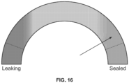
- the controller reads system pressure values from the system pressure sensor over time and determines whether the tubing system is sealed or leaking air based on the system pressure values over time. The controller provides an indication of the determination.
- the electronic processor determines when the tubing system is pressurized based on time passage, a measured system pressure level, or both.
- the indication of the determination also includes a confidence level of the determination.
- the indication is selected from the group of confidently sealed, confidently leaking, and uncertain (e.g., sealed with low confidence or leaking with low confidence)
- the controller reads ambient temperature values from a temperature sensor coupled to the electronic processor.
- the determining of whether the tubing system is sealed or leaking air based on the system pressure values over time is also based on corrections to the system pressure values. The corrections to the system pressure values are based on the system pressure values and the ambient temperature values.
- the controller reads ambient pressure values from an atmospheric pressure sensor that is coupled to the electronic processor.
- the system pressure sensor may be a gage pressure sensor.
- the determining of whether the tubing system is sealed or leaking air based on the system pressure values over time is also based on corrections to the system pressure values. The corrections to the system pressure values are based on the system pressure values, the ambient temperature values, and the ambient pressure values.
- the controller is further configured to indicate results of the determination of whether the tubing system attached to the air output is sealed or leaking air via a communication interface to a user device.
- the controller is further connected to a temperature sensor and reads ambient temperature values from the temperature sensor.
- the controller makes corrections to the pressure level value determined for the tubing system based on one or more pressure level values and the ambient temperature values.
- the pressure sensor is a gage pressure sensor.
- the controller is further configured to read ambient pressure values from an atmospheric pressure sensor and make corrections to the pressure level value determined for the tubing system based on one or more pressure level values, the ambient temperature values, and the ambient pressure values.
- a pressure sensor in some embodiments, includes an air input coupleable to a source of compressed air, an air output, where the air output coupleable to an air fillable system, a valve coupled to the air input, and a pressure sensor that is coupled between the valve and the air output. Air can flow from the air input to the pressure sensor and through the air output when the valve is open.
- the pressure sensor further includes a controller connected to the pressure sensor and the valve.
- the controller includes an electronic processor and a memory that stores instructions that when executed by the processor configure the controller. The controller is configured to open the valve, receive air input through the valve, close the valve when a specified criteria is met, receive pressure sensor data from the pressure sensor, and store the pressure sensor data in the memory.
- a method for a pressure sensor.
- the method includes opening a valve coupled to an air input by an electronic controller where the air input is coupleable to a source of compressed air and air is received through the valve.
- the valve is closed, by the electronic processor, when a specified criteria is met.
- Pressure sensor data is received from the pressure sensor.
- the pressure sensor is coupled between the valve and an air output, where the air output is coupleable to an air fillable system. Air can flow from the air input to the pressure sensor and through the air output when the valve is open.
- the pressure sensor data is stored in memory by an electronic controller.
- the specified criteria is based on time or a pressure level.
- the controller is further configured to analyze the pressure sensor data, generate a user interface based on the pressure sensor data, and transmit the user interface to a display device.
- the electronic controller is configured to transmit the pressure sensor data to a remote server for analysis.
- a pressure sensor system in some embodiments, includes an air input that is coupleable to a source of compressed air and an air output that is coupleable to an air fillable system.
- a valve of the pressure sensor is coupled to the air input.
- the system further includes a pressure sensor coupled between the valve and the air output, where air can flow from the air input to the pressure sensor and through the air output when the valve is open.
- the system further includes a communication interface and a controller connected to the pressure sensor, the valve, and the communication interface.
- the controller includes an electronic processor and a memory that stores instructions that when executed by the processor configure the controller.
- the controller is configured to open the valve, receive air input through the valve, close the valve when a specified criteria is met, receive pressure sensor data from the pressure sensor, and transmit information based on the pressure sensor data via the communication interface to a remote memory.
- the pressure sensor also includes a display device and the controller is configured to analyze the pressure sensor data, generate a user interface based on the pressure sensor data, and transmit the user interface to the display device.
- the controller is configured to transmit the pressure sensor data to a remote server for analysis.
- a method for a pressure sensor.
- the method includes opening a valve by an electronic controller where the valve is coupled to an air input and the air input is coupleable to a source of compressed air. Air is received through the valve and the valve is closed by the electronic processor when a specified criteria is met.
- the electronic controller receives pressure sensor data from a pressure sensor where the pressure sensor is coupled between the valve and an air output. Air can flow from the air input to the pressure sensor and through the air output when the valve is open. The air output is coupleable to an air fillable system.
- the electronic controller further transmits information based on the pressure sensor data via a communication interface to a remote memory.
- the electronic controller is further configured to analyzes the pressure sensor data, generate a user interface based on the pressure sensor data, and transmit the user interface to a display device.
- the electronic controller is further configured to transmit information based on the pressure sensor data to a remote server for analysis.
- a pressure tester includes an air input that is coupleable to a source of compressed air, an air output that is coupleable to an air fillable system, a valve that is coupled to the air input, a user interface, and a pressure sensor.
- the pressure sensor is coupled between the valve and the air output and air can flow from the air input to the pressure sensor and through the air output when the valve is open.
- the pressure sensor system also includes a controller connected to the pressure sensor, the valve, and the user interface.
- the controller includes an electronic processor and a memory storing instructions that when executed by the processor configure the controller to receive an air-fill process initiation command via the user interface, open the valve to receive air via the air input in response to the air-fill process initiation command, and receive pressure sensor data from the pressure sensor.
- the controller is further configured to compare a pressure level indicated by the pressure sensor data to a pressure level threshold close the valve when the pressure level reaches the pressure level threshold.
- the controller is further configured to determine the pressure level threshold based on input received via the user interface.
- the controller is further configured to indicate that the air-fill process is complete via the user interface in response to the closure of the valve when the pressure level reaches the pressure level threshold.
- the pressure sensor system further includes a communication interface, where the controller is further configured to transmit an indication that the air-fill process is complete via the communication interface to a user device.
- the pressure sensor is a gage pressure sensor and the system further includes an atmospheric pressure sensor, where the controller is further configured to read ambient pressure values from the atmospheric pressure sensor, and make corrections to the pressure level value determined for the air fillable system based on one or more pressure level values, the ambient temperature values, and the ambient pressure values.
- a method for filling an air fillable system.
- the method includes receiving, by an electronic controller, an air-fill process initiation command via a user interface, and opening, by the electronic controller, a valve to receive air via an air input in response to the air-fill process initiation command.
- the air input is coupleable to a source of compressed air and air can flow from the air input through an air output when the valve is open and the air output is coupleable to an air fillable system.
- the electronic processor closes the valve when the filling of the air fillable system with air is complete.
- the controller determines whether the filling of the air fillable system with air is complete based on an amount of fill time. In some embodiments, the controller determines whether the filling of the air fillable system with air is complete based on output of a flow meter. In some embodiments, the controller is further configured to indicate that the air-fill process is complete via the user interface in response to the closure of the valve when the pressure level reaches the pressure level threshold. In some embodiments, the controller is further configured to transmit an indication that the air-fill process is complete via a communication interface to a user device.
- embodiments may include hardware, software, and electronic components or modules that, for purposes of discussion, may be illustrated and described as if the majority of the components were implemented solely in hardware.
- electronic based aspects of the embodiments disclosed may be implemented in software (e.g., stored on non-transitory computer-readable medium) executable by one or more processors.
- controllers can include processing components, such as one or more processors, one or more computer-readable medium modules, one or more input/output interfaces, and various connections (e.g., a system bus) connecting the components.
- the controllers described in the specification may be implemented in one of or a combination of a microprocessor, an application specific integrated circuit (ASIC), a digital signal processor (DSP), a field programmable gate array (FPGA), or the like.
- ASIC application specific integrated circuit
- DSP digital signal processor
- FPGA field programmable gate array
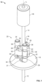
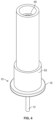
- FIGS. 1-4 illustrate a working element 10 of an expansion tool usable to expand PEX tubing prior to inserting a fitting.
- the working element 10 includes a drive member in the form of a drive shaft 12, a central shaft 14, a back plate 18, and a roller assembly 20.
- the drive shaft 12 is rotatably supported by a bearing 21 within the back plate 18, such that the drive shaft 12 is rotatable relative to the back plate 18 about a longitudinal axis L of the drive shaft 12.
- the roller assembly 20 and the central shaft 14 are coupled for co-rotation with the drive shaft 12 about the longitudinal axis L.
- the drive shaft 12 is configured to be rotated by a drive mechanism (not shown) of the expansion tool.
- the working element 10 may be configured for attachment to other types of rotary power tools, such as drills.
- the roller assembly 20 includes a first arm 22, a second arm 26, and an attachment portion or main body 30.
- the attachment portion 30 is coupled for co-rotation with the drive shaft 12, and in some embodiments, the drive shaft 12 and the attachment portion 30 may be integrally formed together as a single piece.
- the central shaft 14 extends from the attachment portion 30 opposite the drive shaft 12 and may be coupled to the attachment portion 30 by a key and keyway arrangement, a spline interface, or any other suitable rotation-transmitting coupling. Alternatively, the central shaft 14 and the attachment portion 30 may be integrally formed together as a single piece.
- a second or distal end of each of the arms 22, 26 supports a roller shaft 34.
- Each roller shaft 34 extends through the respective arm 22, 26 in a direction parallel to the longitudinal axis L.
- Each of the roller shafts 34 rotatably supports a plurality of generally cylindrical rollers 38.
- each of the roller shafts 34 supports three rollers 38, and the rollers 38 are axially separated by flanges 42 formed at the distal ends of the arms 22, 26.
- the roller shafts 34 may support any number of rollers 38.
- the working element 10 further includes a guide roller 46 rotatably coupled to the central shaft 14 adjacent an end of the central shaft 14 opposite the attachment portion 30.
- the illustrated roller assembly 20 further includes brackets 50 coupled to opposite axial ends of the attachment portion 30.
- the brackets 50 support pivot shafts 54 that pivotally couple the respective arms 22, 26 to the attachment portion 30.
- the brackets 50 may include stops engageable with an associated one of the arms 22, 26 at the retracted position and/or the expanded position to limit movement of the arms 22, 26.
- the working element 10 is inserted into a PEX tube 62 with the arms 22, 26 in the retracted position ( FIG. 2 ), until the back plate 18 abuts the end of the PEX tube 62 ( FIG. 4 ).
- the drive shaft 12 is then rotationally driven by the drive mechanism of the expansion tool at a high speed.
- the drive shaft 12 may be driven at speeds between about 10,000 RPM and about 25,000 RPM.
- the drive shaft 12 may be driven at speeds between about 15,000 RPM and about 20,000 RPM.
- the drive shaft 12 is driven at about 18,000 RPM.
- the rollers 38 travel along the inner circumference of the PEX tube 62. Due to inertia, the rollers 38 exert an apparent centrifugal force on the inside of the PEX tube 62 that is equal to the centripetal force on the rollers 38. This force causes the PEX tube 62 to resiliently expand as the arms 22, 26 move toward the expanded position ( FIG. 3 ).
- the guide roller 42 ( FIG. 1 ), which is inserted deeper into the PEX tube 62, supports the central shaft 14 and stabilizes the working element 10. Once the arms 22, 26 reach the expanded position and expansion is complete, the user may remove the working element 10 from the expanded PEX tube 62. The user then inserts a fitting into the expanded PEX tube 62, and the tube 62 recovers to form a seal around the fitting.
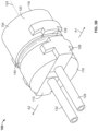
- FIG. 5A-7 illustrate a working element 100 of an expansion tool according to another embodiment.
- the illustrated working element 100 is configured to be coupled to an expansion tool and rotated about a longitudinal axis 124 via a drive mechanism of the expansion tool to expand PEX tubing.
- the working element 100 includes a housing or main body 104 and first and second roller supports 108, 112 slidably coupled to the housing 104.
- the illustrated housing 104 has a front surface 116, a rear surface 118, and a circumferential surface 120 extending between the front and rear surfaces 116, 118.
- the longitudinal axis 124 passes through a center of each of the front surface 116 and the rear surface 118.
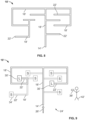
- the first and second roller supports 108, 112 are moveable in relation to the housing 104 between a retracted position ( FIG. 5A ) and an expanded position ( FIG. 5B ).
- the first roller support 108 is movable from the retracted position to the expanded position in a first direction A1
- the second roller support 112 is movable from the retracted position to the expanded position in a second direction A2 that is opposite the first direction A1.
- the first and second directions A1, A2 are substantially transverse to the longitudinal axis 124.
- a first cylindrical roller 128 extends forward from the first roller support 108, and a second cylindrical roller 132 extends forward from the second roller support 112 parallel with the first roller 128.
- the first and second rollers 128, 132 are each parallel with the longitudinal axis 124.
- the first and second rollers 128, 132 are moveable together with the first and second roller supports 108, 112 as the first and second roller supports 108, 112 move in the first and second directions A1, A2.
- the illustrated working element 100 includes two roller supports 108, 112 and two rollers 128, 132
- the working element 100 may include three or more roller supports and accompanying rollers in other embodiments. In such embodiments, each of the roller supports and rollers may be movable relative to the housing 104 in a radial direction.
- the housing 104 and the roller supports 108, 112 collectively define an annular groove 136 that extends around the circumference of the housing 104.
- a resilient ring 140 such as a rubber O-ring, is disposed in the groove 136.
- the ring 140 acts as a biasing member to bias the first and second roller supports 108, 112 toward the retracted position illustrated in FIG. 5A . Movement of the roller supports 108, 112 toward the expanded position resiliently stretches the ring 140.
- the roller supports 108, 112 may be biased toward the retracted position by one or more tension springs coupled to and spanning between the roller supports 108, 112. Alternatively, the roller supports 108, 112 may be biased toward the retracted position by any other suitable biasing means.
- an inner side of each of the roller supports 108, 112 includes an angled cam surface 144.
- the cam surfaces 144 form a substantially triangular-shaped recess when the roller supports 108, 112 are in the retracted position, which receives an expanding member or mandrel 148.
- a distal end 152 of the expanding member 148 includes corresponding angled surfaces that are engageable with the cam surfaces 144 of the roller supports 108, 112.
- movement of the expanding member 148 in the direction of arrow A3 moves the roller supports 108, 112 outward toward the expanded position.
- the roller supports 108, 112 may be moved outward in other ways.
- the expanding member 148 may include a circumferential cam surface configured to expand the roller supports 108, 112 in response to rotation of the expanding member 148.
- an opening 156 is formed in the rear surface 118 of the housing 104 such that the expanding member 148 is accessible through the housing 104.
- a drive member (not shown) of the expansion tool is operable to engage with the expanding member 148 through the opening 156 in order to press the expanding member 148 forward against the cam surfaces 144.
- the force exerted onto the cam surfaces 144 by the expanding member 148 overcomes a spring force exerted onto the first and second sections 108, 112 by the resilient ring 120. This causes the first and second sections 108, 112, as well as the first and second rollers 128, 132, to move in the first and second directions A1, A2, respectively.
- the housing 114 may be axially fixed to the expansion tool to resist the axial reaction force generated by advancing the expanding member 148.
- the housing 114 may be coupled to a gear case of the expansion tool via one or more bearings.
- the illustrated opening 156 has a square shape that forms a rotation-transmitting coupling with the drive member of the expansion tool. As such, once the first and second sections 108, 112 have been moved to the expanded position, the drive member is operable to rotate the housing 104, thereby rotating the first and second rollers 128, 132. In other embodiments, the opening 156 may interface with the drive member in other ways (e.g., a spline interface, etc.).
- the first and second rollers 128, 132 are inserted into a PEX tube to be expanded (e.g., until the front surface 116 of the housing 104 abuts an end of the tubing).
- the drive member forces the expanding member 148 forward in the direction of arrow A3 ( FIG. 7 ).
- the distal end 152 of the expanding member 148 bears against the cam surfaces 144 of the roller supports 108, 122 such that the first and second rollers 128, 132 expand to a distance corresponding with a desired expansion of the PEX tubing ( FIG. 5B ).
- a drive mechanism in the expansion tool may translate the working element 100 to insert the roller supports 108, 112 into a PEX tube to be expanded in addition to rotating the working element 100.
- the drive member rotates the housing 104 about the longitudinal axis 124, thereby rotating the first and second rollers 128, 132 and, thus, expanding the entire inner circumference of the PEX tube.
- the drive member is retracted, and the resilient ring 140 restores the first and second roller supports 108, 112 back to the retracted position ( FIG. 5A ).
- working element 100 may be removed from the PEX tube and a fitting inserted into the tube. The expanded PEX tube recovers to form a seal around the fitting.
- the operation of the working element 100 can be controlled in various ways to achieve a desired expansion performance (e.g., expansion diameter, desired recovery time, etc.).
- a desired expansion performance e.g., expansion diameter, desired recovery time, etc.
- the rate and/or distance that the drive member moves the expanding member 148 may be variable.
- the rotational speed and/or duration that the drive member rotates the housing 104 may also be variable.
- one or more of these parameters may be automatically varied based on a selected size of PEX tube to be expanded.
- Typical working heads for PEX expansion tools include a plurality of jaws that repeatedly expand and retract to gradually expand the end of a PEX tube. Because there are gaps between adjacent jaws that form when the jaws expand, the jaws typically leave impressions in the inner circumference of the PEX tube that may result in gaps and leakage around an inserted fitting.
- the working elements 10, 100 described above with reference to FIGS. 1-7 each use rollers to smoothly increase the diameter of the PEX tubing. Thus, the working elements 10, 100 advantageously leave no impressions in the inner circumference of the PEX tube, and the PEX tube may develop a more reliable seal with an inserted fitting.
- a PEX expansion tool such as a PEX expansion tool including the working element 10 or the working element 100 described above with reference to FIGS. 1-7
- the present disclosure further provides systems and methods for testing the integrity of tubing system.
- FIG. 9 illustrates a leak identifying and sealing system 24' according to one embodiment, which may be used to identify and seal leaks that may exist at any of the fittings of the PEX tubing system 10'.
- the illustrated system 24' includes a source of hot air 26' that may be coupled to the inlet 14' of the tubing system 10'.
- the source of hot air 26' may be a heat pump or the like. As the source of hot air 26' begins to supply hot air into the inlet 14', the hot air will only flow through the segments 18' of the tubing system 10' that lead to a leaking fitting 30', due to the hot air escaping around the leaking fitting 30'.
- the user 42' connects the source of hot air 26' to the inlet 14' of the tubing system 10' at step 100'.
- Power is supplied to the source of hot air 26' to pump the hot air into the tubing system 10'.
- the hot air flows through any segments 18' of the tubing system 10' that lead to a leaking fitting 30'.
- the hot air itself may seal the leak by accelerating recovery of the associated connection end 22 around the leaking fitting 30'.
Landscapes
- Engineering & Computer Science (AREA)
- Mechanical Engineering (AREA)
- Examining Or Testing Airtightness (AREA)
- Measuring Fluid Pressure (AREA)
Claims (13)
- Arbeitselement (10, 100), das funktionsfähig ist, um ein Ende einer Röhre (62) aufzuweiten, wobei das Arbeitselement Folgendes umfasst:einen Hauptkörper (30, 104), der dafür konfiguriert ist, sich um eine Achse (L, 124) zu drehen,eine Vielzahl von Walzenträgern (22, 26, 108, 112), die beweglich an den Hauptkörper gekoppelt sind, wobei die Walzenträger im Verhältnis zu dem Hauptkörper zwischen einer eingezogenen Position und einer ausgefahrenen Position beweglich sind, undeine Vielzahl von Walzen (38, 128, 132), die derart an die Walzenträger gekoppelt sind, dass ein Abstand zwischen einer ersten Walze von der Vielzahl von Walzen und einer zweiten Walze von der Vielzahl von Walzen zunimmt, wenn sich die Walzenträger zu der ausgefahrenen Position hin bewegen,wobei die Walzen dafür konfiguriert sind, in das Ende der Röhre eingeführt zu werden, wenn sich die Walzenträger in der eingezogenen Position befinden, unddadurch gekennzeichnet, dassdie Walzen mit einem Innenumfang der Röhre in Eingriff gebracht werden können, wenn sich der Hauptkörper um die Achse dreht, um das Ende der Röhre durch Zentrifugalkraft aufzuweiten.
- Arbeitselement (10, 100) nach Anspruch 1, wobei die Walzenträger (22, 26, 108, 112) verschiebbar an den Hauptkörper (30, 104) gekoppelt sind.
- Arbeitselement (10, 100) nach Anspruch 1, wobei die Walzenträger (22, 26, 108, 112) schwenkbar an den Hauptkörper (30, 104) gekoppelt sind.
- Arbeitselement (10, 100) nach Anspruch 1, wobei die Walzenträger (22, 26, 108, 112) als Reaktion auf eine Drehung des Hauptkörpers (30, 104) um die Achse (L, 124) zu der ausgefahrenen Position hin beweglich sind.
- Arbeitselement (10, 100) nach Anspruch 1, wobei der Hauptkörper (30, 104) dafür konfiguriert ist, sich mit einer Winkelgeschwindigkeit zwischen 10 000 U/min und 25 000 U/min um die Achse (L, 124) zu drehen.
- Arbeitselement (10, 100) nach Anspruch 1, wobei jeder von den Walzenträgern (22, 26, 108, 112) ein erstes Ende, das an den Hauptkörper (30, 104) gekoppelt ist, und ein zweites Ende, das mindestens eine von den Walzen (38, 128, 132) trägt, einschließt.
- Arbeitselement (10, 100) nach Anspruch 6, wobei jeder von den Walzenträgern (22, 26, 108, 112) eine gekrümmte Form aufweist.
- Arbeitselement (10) nach Anspruch 1, das ferner eine Antriebswelle (12) umfasst, die für eine gemeinsame Drehung mit dem Hauptkörper (30) gekoppelt ist, wobei sich die Antriebswelle von dem Hauptkörper aus in einer ersten Richtung erstreckt, und wobei das Arbeitselement ferner eine mittige Welle (14) umfasst, die sich von dem Hauptkörper aus in einer zweiten Richtung entgegengesetzt zu der ersten Richtung erstreckt.
- Arbeitselement (10) nach Anspruch 8, das ferner eine Führungswalze (46) umfasst, die drehbar an die mittige Welle (14) gekoppelt ist.
- Arbeitselement (10) nach Anspruch 9, wobei die Führungswalze (46) dafür konfiguriert ist, in das Ende der Röhre (62) eingeführt zu werden, um das Arbeitselement während einer Aufweitungsoperation mindestens teilweise zu tragen.
- Arbeitselement (10, 100) nach einem der Ansprüche 8 bis 10, wobei die Antriebswelle (12) dafür konfiguriert ist, mit einer Winkelgeschwindigkeit zwischen 10 000 U/min und 25 000 U/min drehbar angetrieben zu werden, wenn die Walzen (38) mit dem Innenumfang der Röhre in Eingriff gebracht sind.
- Arbeitselement (10, 100) nach einem der Ansprüche 5 oder 11, wobei die Winkelgeschwindigkeit etwa 18 000 U/min beträgt.
- Arbeitselement (10) nach einem der Ansprüche 8 bis 12, das ferner eine Platte (18) umfasst, die zwischen einem Ende der Antriebswelle (12) und dem Hauptkörper (30) angeordnet ist, wobei die Antriebswelle im Verhältnis zu der Platte drehbar ist.
Applications Claiming Priority (5)
| Application Number | Priority Date | Filing Date | Title |
|---|---|---|---|
| US201962855044P | 2019-05-31 | 2019-05-31 | |
| US201962855386P | 2019-05-31 | 2019-05-31 | |
| US201962861361P | 2019-06-14 | 2019-06-14 | |
| US201962923964P | 2019-10-21 | 2019-10-21 | |
| PCT/US2020/034733 WO2020243191A1 (en) | 2019-05-31 | 2020-05-27 | Tubing expansion tools and systems and methods for leak detection |
Publications (3)
| Publication Number | Publication Date |
|---|---|
| EP3976287A1 EP3976287A1 (de) | 2022-04-06 |
| EP3976287A4 EP3976287A4 (de) | 2023-10-25 |
| EP3976287B1 true EP3976287B1 (de) | 2025-07-02 |
Family
ID=73552677
Family Applications (1)
| Application Number | Title | Priority Date | Filing Date |
|---|---|---|---|
| EP20815534.1A Active EP3976287B1 (de) | 2019-05-31 | 2020-05-27 | Rohraufweitungswerkzeug |
Country Status (3)
| Country | Link |
|---|---|
| US (2) | US12145189B2 (de) |
| EP (1) | EP3976287B1 (de) |
| WO (1) | WO2020243191A1 (de) |
Families Citing this family (3)
| Publication number | Priority date | Publication date | Assignee | Title |
|---|---|---|---|---|
| TWI787850B (zh) * | 2021-06-01 | 2022-12-21 | 聯曜實業有限公司 | 成型設備及成型方法 |
| CN114042789B (zh) * | 2021-12-02 | 2022-08-09 | 上海交通大学 | 板材随动式机器人柔性渐进翻边成形优化方法 |
| CN118847849B (zh) * | 2024-09-25 | 2024-12-03 | 江苏鑫科天建化工设备制造有限公司 | 一种用于蒸发器铜管加工的扩孔装置 |
Family Cites Families (10)
| Publication number | Priority date | Publication date | Assignee | Title |
|---|---|---|---|---|
| BE755347A (fr) * | 1969-09-04 | 1971-02-01 | Wavin Bv | Werkwijze voor het vervormen van een kunststofbuis onder aanbrengen vaneen of meer inwendige groeven |
| AU498702B2 (en) * | 1975-03-12 | 1979-03-22 | Sekisui Kagaku Kogyo Kabushiki Kaisha | Forming an annular groove ina thermoplastic pipe |
| JP2000271677A (ja) | 1999-03-29 | 2000-10-03 | Calsonic Kansei Corp | 筒体端部のフレア加工方法及びその装置 |
| GB0128667D0 (en) * | 2001-11-30 | 2002-01-23 | Weatherford Lamb | Tubing expansion |
| US7114358B2 (en) * | 2004-01-06 | 2006-10-03 | Arrow Fabricated Tubing, Ltd. | Tube expanding apparatus |
| JP4851815B2 (ja) | 2006-03-01 | 2012-01-11 | 株式会社スギノマシン | 拡管装置 |
| JP4866428B2 (ja) * | 2006-12-18 | 2012-02-01 | 積水化学工業株式会社 | 製管装置およびこの製管装置を用いた既設管の更生工法 |
| CN105057764B (zh) | 2015-07-30 | 2018-05-29 | 陕西百思特模具有限公司 | 切割刀头及其叠加式短u弯套环自动成形机 |
| KR101703089B1 (ko) | 2016-02-02 | 2017-02-06 | 김성식 | 내부보호관을 갖는 금속파이프와 이의 제조방법 |
| JP6388244B1 (ja) * | 2018-03-29 | 2018-09-12 | 大基産業株式会社 | 管端加工装置 |
-
2020
- 2020-05-27 US US17/046,180 patent/US12145189B2/en active Active
- 2020-05-27 WO PCT/US2020/034733 patent/WO2020243191A1/en not_active Ceased
- 2020-05-27 EP EP20815534.1A patent/EP3976287B1/de active Active
-
2024
- 2024-11-19 US US18/952,451 patent/US20250073773A1/en active Pending
Also Published As
| Publication number | Publication date |
|---|---|
| US12145189B2 (en) | 2024-11-19 |
| US20250073773A1 (en) | 2025-03-06 |
| WO2020243191A1 (en) | 2020-12-03 |
| EP3976287A1 (de) | 2022-04-06 |
| EP3976287A4 (de) | 2023-10-25 |
| US20220184685A1 (en) | 2022-06-16 |
| WO2020243191A8 (en) | 2021-12-16 |
Similar Documents
| Publication | Publication Date | Title |
|---|---|---|
| US20250073773A1 (en) | Tubing expansion tools and systems and methods for leak detection | |
| CN107076157B (zh) | 用于通过手持通信装置检测泵组件中的故障的方法和系统 | |
| CN111578149B (zh) | 燃气管道泄漏监测方法、设备、系统及存储介质 | |
| CN110107819A (zh) | 一种石化产品输送管道泄露监测预警系统及方法 | |
| US9389165B2 (en) | System responsive to machine vibrations and method of use | |
| JP2016533904A (ja) | パイプ要素に溝を形成するための方法およびデバイス | |
| US10502652B2 (en) | System for monitoring pipeline leakage, pipeline element provided with the system, and method for mounting the monitoring system onto a pipeline | |
| US10309864B1 (en) | Exterior tubing monitoring devices | |
| CN113551840A (zh) | 基于光纤测温技术的阀门内漏监测系统及监测方法 | |
| JP6131217B2 (ja) | 配管容量推定装置、ガス漏れ検査装置、配管容量推定方法、及び配管容量推定プログラム | |
| CN113109004A (zh) | 一种污水管网漏损监测方法及其系统 | |
| CN221184307U (zh) | 工作元件、压力测试仪、压力测试系统和充气系统 | |
| CN116221626B (zh) | 一种基于数学模型的热力管道泄漏检测定位方法及系统 | |
| JP5739084B2 (ja) | ガス漏洩検出装置 | |
| US20250314550A1 (en) | Systems and methods for leakage detection, prevention, and mitigation | |
| CN120466582A (zh) | 一种供水管道漏损识别系统及其识别方法 | |
| JP2016045009A (ja) | 配管の検査装置および検査方法 | |
| CN117570378A (zh) | 一种城市天然气管道泄漏检测系统 | |
| CN108187502A (zh) | 反渗透膜壳自动检测装置及其检测方法 | |
| CN208161377U (zh) | 反渗透膜壳自动检测装置 | |
| JP5113771B2 (ja) | 調節弁の漏洩診断装置 | |
| CN114216386A (zh) | 一种管道内表面检测方法、系统、存储介质以及智能终端 | |
| CN105090000A (zh) | 一种空间环境模拟器粗抽真空系统的故障诊断方法 | |
| KR101395311B1 (ko) | 누수현황 산출시스템 및 그 방법 | |
| CN213239376U (zh) | 一种管道接口泄漏检测装置 |
Legal Events
| Date | Code | Title | Description |
|---|---|---|---|
| STAA | Information on the status of an ep patent application or granted ep patent |
Free format text: STATUS: THE INTERNATIONAL PUBLICATION HAS BEEN MADE |
|
| PUAI | Public reference made under article 153(3) epc to a published international application that has entered the european phase |
Free format text: ORIGINAL CODE: 0009012 |
|
| STAA | Information on the status of an ep patent application or granted ep patent |
Free format text: STATUS: REQUEST FOR EXAMINATION WAS MADE |
|
| 17P | Request for examination filed |
Effective date: 20211216 |
|
| AK | Designated contracting states |
Kind code of ref document: A1 Designated state(s): AL AT BE BG CH CY CZ DE DK EE ES FI FR GB GR HR HU IE IS IT LI LT LU LV MC MK MT NL NO PL PT RO RS SE SI SK SM TR |
|
| DAV | Request for validation of the european patent (deleted) | ||
| DAX | Request for extension of the european patent (deleted) | ||
| A4 | Supplementary search report drawn up and despatched |
Effective date: 20230922 |
|
| RIC1 | Information provided on ipc code assigned before grant |
Ipc: B29C 57/04 20060101ALI20230918BHEP Ipc: B21C 51/00 20060101ALI20230918BHEP Ipc: B21D 37/16 20060101ALI20230918BHEP Ipc: B21D 41/02 20060101AFI20230918BHEP |
|
| GRAP | Despatch of communication of intention to grant a patent |
Free format text: ORIGINAL CODE: EPIDOSNIGR1 |
|
| STAA | Information on the status of an ep patent application or granted ep patent |
Free format text: STATUS: GRANT OF PATENT IS INTENDED |
|
| INTG | Intention to grant announced |
Effective date: 20250129 |
|
| GRAS | Grant fee paid |
Free format text: ORIGINAL CODE: EPIDOSNIGR3 |
|
| GRAA | (expected) grant |
Free format text: ORIGINAL CODE: 0009210 |
|
| STAA | Information on the status of an ep patent application or granted ep patent |
Free format text: STATUS: THE PATENT HAS BEEN GRANTED |
|
| AK | Designated contracting states |
Kind code of ref document: B1 Designated state(s): AL AT BE BG CH CY CZ DE DK EE ES FI FR GB GR HR HU IE IS IT LI LT LU LV MC MK MT NL NO PL PT RO RS SE SI SK SM TR |
|
| REG | Reference to a national code |
Ref country code: GB Ref legal event code: FG4D |
|
| REG | Reference to a national code |
Ref country code: CH Ref legal event code: EP |
|
| REG | Reference to a national code |
Ref country code: IE Ref legal event code: FG4D |
|
| REG | Reference to a national code |
Ref country code: DE Ref legal event code: R096 Ref document number: 602020053923 Country of ref document: DE |
|
| REG | Reference to a national code |
Ref country code: NL Ref legal event code: MP Effective date: 20250702 |
|
| PG25 | Lapsed in a contracting state [announced via postgrant information from national office to epo] |
Ref country code: PT Free format text: LAPSE BECAUSE OF FAILURE TO SUBMIT A TRANSLATION OF THE DESCRIPTION OR TO PAY THE FEE WITHIN THE PRESCRIBED TIME-LIMIT Effective date: 20251103 |
|
| PG25 | Lapsed in a contracting state [announced via postgrant information from national office to epo] |
Ref country code: NL Free format text: LAPSE BECAUSE OF FAILURE TO SUBMIT A TRANSLATION OF THE DESCRIPTION OR TO PAY THE FEE WITHIN THE PRESCRIBED TIME-LIMIT Effective date: 20250702 |
|
| REG | Reference to a national code |
Ref country code: AT Ref legal event code: MK05 Ref document number: 1808700 Country of ref document: AT Kind code of ref document: T Effective date: 20250702 |
|
| PG25 | Lapsed in a contracting state [announced via postgrant information from national office to epo] |
Ref country code: IS Free format text: LAPSE BECAUSE OF FAILURE TO SUBMIT A TRANSLATION OF THE DESCRIPTION OR TO PAY THE FEE WITHIN THE PRESCRIBED TIME-LIMIT Effective date: 20251102 |
|
| PG25 | Lapsed in a contracting state [announced via postgrant information from national office to epo] |
Ref country code: NO Free format text: LAPSE BECAUSE OF FAILURE TO SUBMIT A TRANSLATION OF THE DESCRIPTION OR TO PAY THE FEE WITHIN THE PRESCRIBED TIME-LIMIT Effective date: 20251002 |
|
| REG | Reference to a national code |
Ref country code: LT Ref legal event code: MG9D |
|
| PG25 | Lapsed in a contracting state [announced via postgrant information from national office to epo] |
Ref country code: AT Free format text: LAPSE BECAUSE OF FAILURE TO SUBMIT A TRANSLATION OF THE DESCRIPTION OR TO PAY THE FEE WITHIN THE PRESCRIBED TIME-LIMIT Effective date: 20250702 |
|
| PG25 | Lapsed in a contracting state [announced via postgrant information from national office to epo] |
Ref country code: FI Free format text: LAPSE BECAUSE OF FAILURE TO SUBMIT A TRANSLATION OF THE DESCRIPTION OR TO PAY THE FEE WITHIN THE PRESCRIBED TIME-LIMIT Effective date: 20250702 |
|
| PG25 | Lapsed in a contracting state [announced via postgrant information from national office to epo] |
Ref country code: HR Free format text: LAPSE BECAUSE OF FAILURE TO SUBMIT A TRANSLATION OF THE DESCRIPTION OR TO PAY THE FEE WITHIN THE PRESCRIBED TIME-LIMIT Effective date: 20250702 |
|
| PG25 | Lapsed in a contracting state [announced via postgrant information from national office to epo] |
Ref country code: GR Free format text: LAPSE BECAUSE OF FAILURE TO SUBMIT A TRANSLATION OF THE DESCRIPTION OR TO PAY THE FEE WITHIN THE PRESCRIBED TIME-LIMIT Effective date: 20251003 |
|
| PG25 | Lapsed in a contracting state [announced via postgrant information from national office to epo] |
Ref country code: CZ Free format text: LAPSE BECAUSE OF FAILURE TO SUBMIT A TRANSLATION OF THE DESCRIPTION OR TO PAY THE FEE WITHIN THE PRESCRIBED TIME-LIMIT Effective date: 20250702 Ref country code: SE Free format text: LAPSE BECAUSE OF FAILURE TO SUBMIT A TRANSLATION OF THE DESCRIPTION OR TO PAY THE FEE WITHIN THE PRESCRIBED TIME-LIMIT Effective date: 20250702 |
|
| PG25 | Lapsed in a contracting state [announced via postgrant information from national office to epo] |
Ref country code: LV Free format text: LAPSE BECAUSE OF FAILURE TO SUBMIT A TRANSLATION OF THE DESCRIPTION OR TO PAY THE FEE WITHIN THE PRESCRIBED TIME-LIMIT Effective date: 20250702 |
|
| PG25 | Lapsed in a contracting state [announced via postgrant information from national office to epo] |
Ref country code: PL Free format text: LAPSE BECAUSE OF FAILURE TO SUBMIT A TRANSLATION OF THE DESCRIPTION OR TO PAY THE FEE WITHIN THE PRESCRIBED TIME-LIMIT Effective date: 20250702 Ref country code: BG Free format text: LAPSE BECAUSE OF FAILURE TO SUBMIT A TRANSLATION OF THE DESCRIPTION OR TO PAY THE FEE WITHIN THE PRESCRIBED TIME-LIMIT Effective date: 20250702 |
|
| PG25 | Lapsed in a contracting state [announced via postgrant information from national office to epo] |
Ref country code: RS Free format text: LAPSE BECAUSE OF FAILURE TO SUBMIT A TRANSLATION OF THE DESCRIPTION OR TO PAY THE FEE WITHIN THE PRESCRIBED TIME-LIMIT Effective date: 20251002 |
|
| PG25 | Lapsed in a contracting state [announced via postgrant information from national office to epo] |
Ref country code: ES Free format text: LAPSE BECAUSE OF FAILURE TO SUBMIT A TRANSLATION OF THE DESCRIPTION OR TO PAY THE FEE WITHIN THE PRESCRIBED TIME-LIMIT Effective date: 20250702 |
|
| PG25 | Lapsed in a contracting state [announced via postgrant information from national office to epo] |
Ref country code: SM Free format text: LAPSE BECAUSE OF FAILURE TO SUBMIT A TRANSLATION OF THE DESCRIPTION OR TO PAY THE FEE WITHIN THE PRESCRIBED TIME-LIMIT Effective date: 20250702 |
|
| PG25 | Lapsed in a contracting state [announced via postgrant information from national office to epo] |
Ref country code: DK Free format text: LAPSE BECAUSE OF FAILURE TO SUBMIT A TRANSLATION OF THE DESCRIPTION OR TO PAY THE FEE WITHIN THE PRESCRIBED TIME-LIMIT Effective date: 20250702 |
|
| PG25 | Lapsed in a contracting state [announced via postgrant information from national office to epo] |
Ref country code: IT Free format text: LAPSE BECAUSE OF FAILURE TO SUBMIT A TRANSLATION OF THE DESCRIPTION OR TO PAY THE FEE WITHIN THE PRESCRIBED TIME-LIMIT Effective date: 20250702 |
|
| PG25 | Lapsed in a contracting state [announced via postgrant information from national office to epo] |
Ref country code: EE Free format text: LAPSE BECAUSE OF FAILURE TO SUBMIT A TRANSLATION OF THE DESCRIPTION OR TO PAY THE FEE WITHIN THE PRESCRIBED TIME-LIMIT Effective date: 20250702 Ref country code: SK Free format text: LAPSE BECAUSE OF FAILURE TO SUBMIT A TRANSLATION OF THE DESCRIPTION OR TO PAY THE FEE WITHIN THE PRESCRIBED TIME-LIMIT Effective date: 20250702 |
|
| PLBE | No opposition filed within time limit |
Free format text: ORIGINAL CODE: 0009261 |
|
| STAA | Information on the status of an ep patent application or granted ep patent |
Free format text: STATUS: NO OPPOSITION FILED WITHIN TIME LIMIT |