EP3976440B1 - Système ferroviaire avec rail et pièces mobiles mobiles le long du rail - Google Patents
Système ferroviaire avec rail et pièces mobiles mobiles le long du rail Download PDFInfo
- Publication number
- EP3976440B1 EP3976440B1 EP20729627.8A EP20729627A EP3976440B1 EP 3976440 B1 EP3976440 B1 EP 3976440B1 EP 20729627 A EP20729627 A EP 20729627A EP 3976440 B1 EP3976440 B1 EP 3976440B1
- Authority
- EP
- European Patent Office
- Prior art keywords
- rail
- cavity
- absorber
- rail system
- shaped part
- Prior art date
- Legal status (The legal status is an assumption and is not a legal conclusion. Google has not performed a legal analysis and makes no representation as to the accuracy of the status listed.)
- Active
Links
Images




Classifications
-
- B—PERFORMING OPERATIONS; TRANSPORTING
- B61—RAILWAYS
- B61L—GUIDING RAILWAY TRAFFIC; ENSURING THE SAFETY OF RAILWAY TRAFFIC
- B61L15/00—Indicators provided on the vehicle or train for signalling purposes
- B61L15/0018—Communication with or on the vehicle or train
- B61L15/0027—Radio-based, e.g. using GSM-R
-
- B—PERFORMING OPERATIONS; TRANSPORTING
- B61—RAILWAYS
- B61L—GUIDING RAILWAY TRAFFIC; ENSURING THE SAFETY OF RAILWAY TRAFFIC
- B61L15/00—Indicators provided on the vehicle or train for signalling purposes
- B61L15/0018—Communication with or on the vehicle or train
-
- B—PERFORMING OPERATIONS; TRANSPORTING
- B61—RAILWAYS
- B61L—GUIDING RAILWAY TRAFFIC; ENSURING THE SAFETY OF RAILWAY TRAFFIC
- B61L27/00—Central railway traffic control systems; Trackside control; Communication systems specially adapted therefor
- B61L27/70—Details of trackside communication
-
- B—PERFORMING OPERATIONS; TRANSPORTING
- B61—RAILWAYS
- B61L—GUIDING RAILWAY TRAFFIC; ENSURING THE SAFETY OF RAILWAY TRAFFIC
- B61L3/00—Devices along the route for controlling devices on the vehicle or train, e.g. to release brake or to operate a warning signal
- B61L3/16—Continuous control along the route
- B61L3/22—Continuous control along the route using magnetic or electrostatic induction; using electromagnetic radiation
- B61L3/225—Continuous control along the route using magnetic or electrostatic induction; using electromagnetic radiation using separate conductors along the route
-
- B—PERFORMING OPERATIONS; TRANSPORTING
- B61—RAILWAYS
- B61L—GUIDING RAILWAY TRAFFIC; ENSURING THE SAFETY OF RAILWAY TRAFFIC
- B61L3/00—Devices along the route for controlling devices on the vehicle or train, e.g. to release brake or to operate a warning signal
- B61L3/16—Continuous control along the route
- B61L3/22—Continuous control along the route using magnetic or electrostatic induction; using electromagnetic radiation
- B61L3/227—Continuous control along the route using magnetic or electrostatic induction; using electromagnetic radiation using electromagnetic radiation
-
- B—PERFORMING OPERATIONS; TRANSPORTING
- B61—RAILWAYS
- B61L—GUIDING RAILWAY TRAFFIC; ENSURING THE SAFETY OF RAILWAY TRAFFIC
- B61L3/00—Devices along the route for controlling devices on the vehicle or train, e.g. to release brake or to operate a warning signal
- B61L3/16—Continuous control along the route
- B61L3/22—Continuous control along the route using magnetic or electrostatic induction; using electromagnetic radiation
- B61L2003/228—Constructional details
-
- H—ELECTRICITY
- H01—ELECTRIC ELEMENTS
- H01P—WAVEGUIDES; RESONATORS, LINES, OR OTHER DEVICES OF THE WAVEGUIDE TYPE
- H01P3/00—Waveguides; Transmission lines of the waveguide type
- H01P3/12—Hollow waveguides
Definitions
- the invention relates to a rail system with a rail and mobile parts that can be moved along the rail.
- a rail system is designed with a rail and mobile parts that can be moved along the rail.
- the closest state of the art is a device for ensuring the distance between track-bound vehicles.
- a conductor rail system is known from DE 20 2016 104 836 U1.
- a communication system is known from the "smg slotted microwave guide" from Vahle Communication Systems.
- a transport system is known from DE 10 2012 006 412 A1.
- the invention is therefore based on the object of developing a rail system in which data transmission is to be carried out more simply and cost-effectively.
- the object is achieved in the rail system according to the features specified in claim 1.
- the advantage here is that data can be transmitted between movable handsets by sending and receiving modulated light. Furthermore, the data can also be transmitted between the movable handset and stationary transmitters and receivers.
- the use of a profile part which has an opening slot extending in the direction of the rail enables interference-free or at least low-interference data transmission. This is because light coming from the environment can be almost completely shielded.
- the range of the data transmission is increased because the light intensity decreases more slowly with increasing distance in the cavity than in free space. The narrower the slot, the lower the losses and thus the greater the range.
- the handset has leg areas that protrude into the cavity, which hold a transmitter and receiver into the cavity.
- an absorber is arranged in the rail direction between the areas of the mobile part,
- the absorber is made of a brush, fleece, or plastic.
- the absorber touches the profile part in a circumferential angular range of more than 180° relative to the rail direction, or is at least closer to the profile part than the areas of the mobile part or than the mobile part itself. It is advantageous that the absorber can be provided almost touching the profile part or even rubbing against the profile part.
- the transmitter and receiver arranged in a respective area, in particular the leg area, of the mobile part are each arranged on the side of the area facing away from the absorber.
- a first spatial area for data transmission arranged at the front in the rail direction, is separated by the absorber from a second spatial area for data transmission, arranged at the rear in the rail direction.
- the data transmission channel located in the cavity in front of the respective absorber in the direction of the rail is separated from the data transmission channel located in the cavity in the direction of the rail behind the absorber. This is advantageous in that low-interference data transmission is enabled.
- the advantage here is that data can be transmitted not only via the slotted waveguide, but also via light within the same spatial area. This allows for either a higher data transmission rate or greater security, since the data can be transmitted using two different physical principles.
- the mobile unit is movable and guided along the rail by means of wheels and/or rollers. It is advantageous that the mobile unit is designed as a rail vehicle.
- an LED or a laser diode for visible or infrared light is used as the transmitter and/or A photodiode or phototransistor is used as a receiver to detect visible or infrared light.
- a photodiode or phototransistor is used as a receiver to detect visible or infrared light.
- the advantage here is that light can be used.
- a transmitter and a receiver are accommodated in a recess of the profile part,
- the recess is a round hole or a bore whose round hole symmetry axis or bore axis forms an angle of between 10° and 60° to the rail direction, and/or the recess extends continuously through the profile part and/or through the wall of the profile part.
- the profile part is in one piece with the rail, In particular, it is designed as a single piece.
- the advantage here is that the profile part is integrated with the rail, eliminating the need for precise relative alignment prior to joining, since the production as a continuous casting already results in the integrated rail part.
- the profile part has two cavities extending parallel to one another, in particular spaced apart from one another. This advantageously allows for the use of not only a monochrome half-duplex method, but also a monochrome full-duplex method for data transmission.
- the profile part has only a single, elongated cavity.
- the advantage here is that a full-duplex process can be implemented by using two different colors, even if only a single, non-separated communication medium is available.
- the cross-section of the respective cavity is invariant, in particular unchangeable, along the rail direction.
- the profile part can be manufactured as a drawn part or as a continuous cast part.
- the cross-section in the initially formed profile part is constant. Round holes or bores can then be drilled into the profile part as post-processing to accommodate the stationary transmitter and receiver. If the profile part is made of plastic, a coating can also be applied.
- the opening of the respective cavity or cavities is designed as a slot extending in the direction of the rail. This is advantageous in that the mobile part, during its movement, can protrude into the cavity through the slot by means of the regions, in particular the leg regions, and can be moved parallel to the slot. Therefore, it is important that the slot direction is aligned parallel to the rail direction.
- the profile part is made of plastic, in particular as a drawn part, or that the profile part is made of metal, in particular as an extruded aluminium part.
- the advantage here is that simple, cost-effective production is possible and the profile part has the same translational symmetry as the rail, in particular which itself is manufactured as a continuous casting or drawn part.
- the profile part 5 has a cavity which is open towards a first side.
- the profile part 5 is arranged parallel to a rail of a system designed as a rail system.
- the rail is preferably made as a metal profile part.
- the profile part 5 is preferably made of plastic, with the cavity of the profile part 5 having mirrored side surfaces.
- the mirroring is preferably produced by vapor deposition with the metal, in particular chromium or a chromium-containing alloy.
- each mobile unit 6 extends at least partially into the cavity of the profile part 5, so that each mobile unit 6 has a transmitter 4 and a receiver 3 on the front side in the direction of the rail. Likewise, each mobile unit 6 also has a transmitter 4 and a receiver 3 on its rear side.
- the mobile unit 6 In the rail direction, between the transmitter 4 and receiver 3 on the front and rear sides, the mobile unit 6 has an absorber that absorbs the radiation emitted by the transmitters 4, in particular light radiation. In this way, the cavity in front of the absorber 7 in the rail direction and the cavity behind the absorber 7 in the opposite direction to the rail direction are separated from the radiation, thus forming two separate data communication areas.
- the handset 6 is able to exchange data with another handset 6 spaced apart in the direction of the rail and also with a third handset 6 spaced apart opposite to the direction of the rail.
- the handsets 6 are constructed identically to one another.
- At least one transmitter 2 and one receiver 1 are stationary on the profile part 5.
- data can also be transmitted between a mobile unit 6 and the stationary transmitter 2 and receiver 1.
- the cavity formed in profile part 5 has a cross-sectional profile that remains constant in the rail direction. This is because profile part 5 can be manufactured as a continuous casting.
- the cavity is open to the environment, the clear width of the cavity narrows increasingly with decreasing distance from the cavity's opening to the environment.
- the cavity has a slit as its opening and/or mouth.
- An LED for the visible or infrared light range can preferably be used as the transmitter (2, 4) and a correspondingly light-sensitive component, such as a phototransistor or photodiode, can be used as the receiver (1, 3).
- a correspondingly light-sensitive component such as a phototransistor or photodiode
- the respective absorber 7 is arranged on the respective mobile part 6 in such a way that the distance to the profile part 5 is as small as possible, in particular disappears.
- the area of the mobile part 6 which projects into the cavity is designed with two leg areas spaced apart from one another in the direction of the rail, in particular in a U-shape.
- a transmitter 4 and a receiver 3 are arranged on each of the two legs.
- Absorber 7 is arranged on the mobile unit between the two legs, facing the rail. Absorber 7 preferably extends beyond the legs in all transverse directions relative to the rail.
- transmitters 2 and 4 are all operated with the same frequency, i.e. color, only a half-duplex method can be used for data transmission.
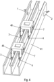
- the profile part there is designed with two parallel cavities. Each of these cavities is similar to the cavity in the embodiment according to Figures 1 to 3 .
- the mobile part 40 now extends into both cavities.
- the mobile part 40 preferably has two leg regions for each cavity, so that a transmitter 4 and a receiver 3 are arranged in each cavity at a respective leg region in the rail direction, and a transmitter 4 and a receiver 3 are arranged at a respective leg region opposite to the rail direction.
- an absorber 7 is arranged in the rail direction between the two respective leg areas, in particular according to the design according to Figures 1 to 3
- the cavity is thus separated by the absorber 7, particularly for light.
- the absorber 7 particularly for light.
- In the direction of the rail in front of the mobile part spreading light is separated from the area of the room arranged behind the handset in the direction of the rail.
- the respective profile part (5, 41) is made of a metal, such as aluminum.
- the surface of the material bordering the respective cavity reflects radiation, in particular visible or infrared light.
- the respective profile part (5, 41) can be manufactured from plastic, in particular as a plastic profile part.
- the surface of the material bordering the respective cavity is coated with a radiation-reflecting layer, in particular with a chromium layer or chromium-containing layer.
- the rail and the profile part (5, 41) are made of the same material and are therefore integral, i.e., one-piece.
- the cavity or cavities are integrally formed on the rail. Therefore, only the rail needs to be installed when manufacturing the rail system.
- the mobile parts (6, 40) are then placed on the rail, and their leg portions extend into the cavities, so that transmitters 4 and receivers 3 arranged on the leg portions radiate radiation into the cavities.
Landscapes
- Engineering & Computer Science (AREA)
- Mechanical Engineering (AREA)
- Physics & Mathematics (AREA)
- Electromagnetism (AREA)
- Health & Medical Sciences (AREA)
- General Health & Medical Sciences (AREA)
- Toxicology (AREA)
- Optical Communication System (AREA)
- Length Measuring Devices By Optical Means (AREA)
Claims (13)
- Installation ferroviaire comprenant un rail et des parties mobiles pouvant être mues le long dudit rail, des véhicules ferroviaires en particulier,sachant qu'une pièce profilée (5), disposée sur ledit rail, est munie d'une première cavité débouchant notamment dans l'espace environnant, au niveau d'une ouverture,sachant que des régions d'une partie mobile (6), de chaque partie mobile (6) en particulier, s'engagent au moins partiellement dans la première cavité,au moins un émetteur (2) et un récepteur (1) étant implantés au niveau de la région considérée,caractérisée par le fait quela pièce profilée (5) est dotée d'une seconde cavité,la première cavité et la seconde cavité s'étendant parallèlement l'une à l'autre et étant notamment distantes l'une de l'autre,un émetteur (4) supplémentaire et un récepteur (3) supplémentaire de la partie mobile (6) étant logés dans ladite seconde cavité.
- Installation ferroviaire selon la revendication 1,
caractérisée par le faitqu'un absorbeur (7) est fixé à la partie mobile (6),un absorbeur (7) respectif étant interposé entre les régions de ladite partie mobile (6) dans la direction du rail,sachant, en particulier, que ledit absorbeur (7) est fabriqué à partir d'une brosse, à partir d'un non-tissé, ou en une matière plastique. - Installation ferroviaire selon la revendication 2,
caractérisée par le fait que
l'absorbeur (7) est en contact avec la pièce profilée (5) dans une plage d'angles périphériques couvrant plus de 180° ou est pour le moins situé, par rapport à ladite pièce profilée (5), à une plus faible distance que les régions de la partie mobile (6) ou que ladite partie mobile (6), notamment que ladite partie mobile (6) ne comportant pas ledit absorbeur (7). - Installation ferroviaire selon l'une des revendications 2 ou 3,
caractérisée par le fait que
l'émetteur (2) et le récepteur (1) implantés au niveau d'une région respective sont disposés, à chaque fois, sur un côté de ladite région qui est tourné à l'opposé de l'absorbeur (7). - Installation ferroviaire selon l'une des revendications 2, 3 ou 4,
caractérisée par le faitqu'un canal de transmission de données intégré dans la première cavité, devant l'absorbeur respectif (7) dans la direction du rail, est placé distinctement, en particulier au moyen de l'absorbeur (7) concernant notamment la lumière diffusée par l'émetteur (2) considéré,vis-à-vis d'un canal de transmission de données intégré, dans ladite première cavité, derrière ledit absorbeur (7) dans la direction dudit rail. - Installation ferroviaire selon l'une des revendications précédentes,
caractérisée par le fait que
la partie mobile (6) peut être mue et est guidée, sur le rail, au moyen de roues et/ou de rouleaux. - Installation ferroviaire selon l'une des revendications précédentes,
caractérisée par le faitqu'une DEL, ou une diode laser dévolue à une lumière visible ou infrarouge, est utilisée en tant qu'émetteur (2) ;
et/ou par le faitqu'une photodiode ou un phototransistor est employé(e), en tant que récepteur (1), en vue de la détection d'une lumière visible ou infrarouge. - Installation ferroviaire selon l'une des revendications précédentes,
caractérisée par le faitqu'un émetteur (4) supplémentaire et un récepteur (3) supplémentaire sont logés dans un évidement de la pièce profilée (5),sachant que l'évidement se présente, en particulier, comme un trou circulaire ou comme un alésage, l'axe de symétrie dudit trou circulaire ou l'axe dudit alésage décrivant un angle compris entre 10° et 60° par rapport à la direction du rail, et/ou sachant que ledit évidement est pratiqué, de manière continue, à travers la pièce profilée (5) et/ou à travers la paroi de ladite pièce profilée (5). - Installation ferroviaire selon l'une des revendications précédentes,
caractérisée par le fait que
la pièce profilée (5) est réalisée d'un seul tenant, notamment d'un seul bloc avec le rail. - Installation ferroviaire selon l'une des revendications précédentes,
caractérisée par le fait que
la section transversale de la cavité considérée est invariable, notamment immuable le long de la direction du rail. - Installation ferroviaire selon l'une des revendications précédentes,
caractérisée par le fait que
l'ouverture de la cavité considérée est ménagée en tant que fente s'étendant dans la direction du rail. - Installation ferroviaire selon l'une des revendications précédentes,
caractérisée par le fait quela pièce profilée (5) est fabriquée en matière plastique, notamment en tant que pièce emboutie ;ou par le fait que ladite pièce profilée (5) est fabriquée en métal, notamment en tant que pièce extrudée en aluminium. - Installation ferroviaire selon l'une des revendications précédentes,
caractérisée par le fait quela pièce profilée (5) est pourvue d'une zone de surface revêtue,le revêtement consistant notamment en du chrome, ou en un alliage renfermant du chrome,sachant, en particulier, que ladite zone de surface borde et/ou délimite la cavité considérée.
Applications Claiming Priority (2)
| Application Number | Priority Date | Filing Date | Title |
|---|---|---|---|
| DE102019003762 | 2019-05-29 | ||
| PCT/EP2020/025246 WO2020239264A1 (fr) | 2019-05-29 | 2020-05-26 | Système de rails comprenant un rail et des éléments mobiles pouvant être déplacés le long du rail |
Publications (3)
| Publication Number | Publication Date |
|---|---|
| EP3976440A1 EP3976440A1 (fr) | 2022-04-06 |
| EP3976440B1 true EP3976440B1 (fr) | 2025-03-19 |
| EP3976440C0 EP3976440C0 (fr) | 2025-03-19 |
Family
ID=70921983
Family Applications (1)
| Application Number | Title | Priority Date | Filing Date |
|---|---|---|---|
| EP20729627.8A Active EP3976440B1 (fr) | 2019-05-29 | 2020-05-26 | Système ferroviaire avec rail et pièces mobiles mobiles le long du rail |
Country Status (5)
| Country | Link |
|---|---|
| US (1) | US11999390B2 (fr) |
| EP (1) | EP3976440B1 (fr) |
| CN (1) | CN113891825B (fr) |
| DE (1) | DE102020003147A1 (fr) |
| WO (1) | WO2020239264A1 (fr) |
Families Citing this family (2)
| Publication number | Priority date | Publication date | Assignee | Title |
|---|---|---|---|---|
| CN115977017B (zh) * | 2022-12-26 | 2026-02-17 | 中国水产科学研究院渔业工程研究所 | 应用于港池内侧的环保型护岸结构 |
| DE102025142302A1 (de) | 2024-11-12 | 2026-05-13 | Sew-Eurodrive Gmbh & Co Kg | Einschienenhängebahnsystem |
Family Cites Families (23)
| Publication number | Priority date | Publication date | Assignee | Title |
|---|---|---|---|---|
| DE3117655C2 (de) * | 1981-05-05 | 1985-04-11 | Messerschmitt-Bölkow-Blohm GmbH, 8000 München | Einrichtung zur Abstandsicherung von spurgebundenen Fahrzeugen |
| JPH0428638Y2 (fr) | 1987-06-17 | 1992-07-10 | ||
| GB8718519D0 (en) * | 1987-08-05 | 1987-09-09 | Ml Eng Plymouth | Railway signalling apparatus |
| CH676903A5 (en) | 1988-08-02 | 1991-03-15 | Adcount Ltd | Information transmission system for train - uses coded microwave signals fed between successive train sections |
| US6339397B1 (en) * | 2000-06-01 | 2002-01-15 | Lat-Lon, Llc | Portable self-contained tracking unit and GPS tracking system |
| DE10152380A1 (de) | 2001-10-28 | 2003-06-26 | Pieper Siegfried | Vorrichtung zur Erfassung von Kräften und Veränderungen an Rädern von Schienenfahrzeugen |
| GB0306008D0 (en) | 2003-03-15 | 2003-04-23 | Qinetiq Ltd | Optical device |
| FR2916907B1 (fr) | 2007-05-31 | 2010-09-10 | Alstom Transport Sa | Dispositif de communication pour vehicule ferroviaire |
| CN201553167U (zh) | 2009-10-22 | 2010-08-18 | 史长春 | 机车信息集中控制器 |
| DE102010036521A1 (de) | 2010-07-20 | 2012-01-26 | Era - Contact Gmbh | Vorrichtung zur Übertragung von Daten zwischen zwei Schienenfahrzeugen |
| DE102010050757A1 (de) | 2010-11-10 | 2012-05-10 | Sew-Eurodrive Gmbh & Co. Kg | Anlage mit schienengeführtem Fahrzeug |
| DE102012006412B4 (de) * | 2011-04-15 | 2024-10-31 | Sew-Eurodrive Gmbh & Co Kg | Transportsystem |
| WO2012139702A2 (fr) | 2011-04-15 | 2012-10-18 | Sew-Eurodrive Gmbh & Co. Kg | Système de transport |
| CN202949429U (zh) | 2012-11-14 | 2013-05-22 | 中国铁道科学研究院 | 一种应答器传输模块的检测装置 |
| DE102013002227B4 (de) | 2013-02-11 | 2014-11-13 | Sew-Eurodrive Gmbh & Co Kg | Anordnung zur Signalübertragung und Anlage mit dieser Anordnung |
| DE102013203134B4 (de) | 2013-02-26 | 2017-03-02 | Deutsches Zentrum für Luft- und Raumfahrt e.V. | Kommunikationsvorrichtung und Verfahren zum Austausch von Daten |
| DE102014107468A1 (de) | 2014-05-27 | 2015-12-03 | Conductix-Wampfler Gmbh | Schleifleitung, Stromabnehmer und Schleifleitungssystem |
| DE102016108442A1 (de) * | 2016-05-06 | 2017-11-09 | Conductix-Wampfler Gmbh | Datenübertragungsvorrichtung, Schleifleitung und Schleifleitungssystem |
| DE202016102435U1 (de) | 2016-05-06 | 2017-08-09 | Conductix-Wampfler Gmbh | Datenübertragungsvorrichtung, Schleifleitung und Schleifleitungssystem |
| DE102016116396A1 (de) * | 2016-09-01 | 2018-03-15 | Conductix-Wampfler Gmbh | Schleifleitung, Stromabnehmer, Schleifleitungssystem und Verfahren zur berührungslosen Datenübertragung |
| DE202016104836U1 (de) | 2016-09-01 | 2017-12-04 | Conductix-Wampfler Gmbh | Schleifleitung, Stromabnehmer und Schleifleitungssystem |
| CN206954247U (zh) | 2017-07-14 | 2018-02-02 | 北京欧宁航宇检测技术有限公司 | 地铁或城铁轨道检测车的全自动无人化收发系统 |
| CN108725514B (zh) | 2018-07-23 | 2024-04-02 | 湖南云辙科技有限公司 | 导轨、轨道车辆控制装置、轨道车辆及运输系统 |
-
2020
- 2020-05-26 DE DE102020003147.1A patent/DE102020003147A1/de active Pending
- 2020-05-26 EP EP20729627.8A patent/EP3976440B1/fr active Active
- 2020-05-26 US US17/614,526 patent/US11999390B2/en active Active
- 2020-05-26 WO PCT/EP2020/025246 patent/WO2020239264A1/fr not_active Ceased
- 2020-05-26 CN CN202080039528.3A patent/CN113891825B/zh active Active
Also Published As
| Publication number | Publication date |
|---|---|
| US11999390B2 (en) | 2024-06-04 |
| CN113891825A (zh) | 2022-01-04 |
| DE102020003147A1 (de) | 2020-12-03 |
| WO2020239264A1 (fr) | 2020-12-03 |
| EP3976440C0 (fr) | 2025-03-19 |
| US20220219743A1 (en) | 2022-07-14 |
| EP3976440A1 (fr) | 2022-04-06 |
| CN113891825B (zh) | 2023-12-29 |
Similar Documents
| Publication | Publication Date | Title |
|---|---|---|
| DE19503892C1 (de) | Mit einer elektrischen Leitschicht versehene Autoglasscheibe | |
| EP2954592B1 (fr) | Ensemble, en particulier installation, permettant la transmission de signaux | |
| DE112012001758T5 (de) | Hindernisdetektionsvorrichtung für ein Fahrzeug | |
| EP3976440A1 (fr) | Système de rails comprenant un rail et des éléments mobiles pouvant être déplacés le long du rail | |
| EP2737576B1 (fr) | Ensemble destiné à la transmission de données entre une première partie de l'installation, notamment une partie fixe de l'installation, et une partie mobile pouvant être déplacée par rapport à la première partie de l'installation | |
| EP1933172B1 (fr) | Agencement de barrière lumineuse | |
| EP2812946B1 (fr) | Installation dotée d'un guide d'onde à fente pour la transmission de données | |
| EP2283593A1 (fr) | Transmission de données sans fil par ondes térahertziennes | |
| EP2941861A1 (fr) | Paroi de boîtier | |
| EP3599136B2 (fr) | Dispositif de détection pour un véhicule | |
| DE3441269A1 (de) | Verfahren zur modulation der amplitude der sekundaerkeulen der strahlungscharakteristik einer uhf-antenne, anwendung des verfahrens und filter zur durchfuehrung des verfahrens | |
| EP0888646B1 (fr) | Dispositif d'antenne pour la fixation d'une antenne planaire sur la face interieure de la vitre d'un vehicule automobile | |
| WO2005050879A1 (fr) | Dispositif pour la transmission de donnees entre un composant mobile et un composant fixe | |
| DE102019107274A1 (de) | Vorrichtung zur Kommunikation | |
| EP2815460A1 (fr) | Ensemble de transmission de données entre une première partie d'installation, en particulier fixe, et une partie mobile par rapport à la première partie d'installation | |
| DE102015103983A1 (de) | Schlitzhohlleiter mit geringer Breite | |
| CH676903A5 (en) | Information transmission system for train - uses coded microwave signals fed between successive train sections | |
| DE2104467A1 (de) | Funk Fernmeldesystem in umschlossenen Räumen | |
| DE102013007647B3 (de) | Anlage, umfassend ein entlang einer Schienenstrecke, insbesondere entlang eines Schienenteils, bewegbares Schienenfahrzeug | |
| EP3977644B1 (fr) | Système, notamment installation, comportant une partie mobile et une partie de réception recevant un écran | |
| EP4428487B1 (fr) | Dispositif et procédé pour déterminer l'épaisseur de paroi d'un objet | |
| DE19624745A1 (de) | Richtantenne für Mikrowellenfunktelefone | |
| EP3275085B1 (fr) | Antenne pour applications en champ proche et utilisation d'une telle antenne | |
| DE102020134560B3 (de) | Kraftfahrzeug mit einer Radarsensoranordnung und Verfahren zur Synchronisierung von Radarsensoren | |
| EP0312010A2 (fr) | Dispositif émetteur et récepteur pour la transmission d'information par rayon lumineux |
Legal Events
| Date | Code | Title | Description |
|---|---|---|---|
| STAA | Information on the status of an ep patent application or granted ep patent |
Free format text: STATUS: UNKNOWN |
|
| STAA | Information on the status of an ep patent application or granted ep patent |
Free format text: STATUS: THE INTERNATIONAL PUBLICATION HAS BEEN MADE |
|
| PUAI | Public reference made under article 153(3) epc to a published international application that has entered the european phase |
Free format text: ORIGINAL CODE: 0009012 |
|
| STAA | Information on the status of an ep patent application or granted ep patent |
Free format text: STATUS: REQUEST FOR EXAMINATION WAS MADE |
|
| 17P | Request for examination filed |
Effective date: 20220103 |
|
| AK | Designated contracting states |
Kind code of ref document: A1 Designated state(s): AL AT BE BG CH CY CZ DE DK EE ES FI FR GB GR HR HU IE IS IT LI LT LU LV MC MK MT NL NO PL PT RO RS SE SI SK SM TR |
|
| DAV | Request for validation of the european patent (deleted) | ||
| DAX | Request for extension of the european patent (deleted) | ||
| GRAP | Despatch of communication of intention to grant a patent |
Free format text: ORIGINAL CODE: EPIDOSNIGR1 |
|
| STAA | Information on the status of an ep patent application or granted ep patent |
Free format text: STATUS: GRANT OF PATENT IS INTENDED |
|
| RIC1 | Information provided on ipc code assigned before grant |
Ipc: H01P 3/12 20060101ALN20241009BHEP Ipc: B61L 27/70 20220101ALI20241009BHEP Ipc: B61L 3/22 20060101ALI20241009BHEP Ipc: H01Q 13/22 20060101ALI20241009BHEP Ipc: H01Q 1/32 20060101ALI20241009BHEP Ipc: H01P 3/123 20060101ALI20241009BHEP Ipc: B61L 15/00 20060101AFI20241009BHEP |
|
| RIC1 | Information provided on ipc code assigned before grant |
Ipc: H01P 3/12 20060101ALN20241016BHEP Ipc: B61L 27/70 20220101ALI20241016BHEP Ipc: B61L 3/22 20060101ALI20241016BHEP Ipc: H01Q 13/22 20060101ALI20241016BHEP Ipc: H01Q 1/32 20060101ALI20241016BHEP Ipc: H01P 3/123 20060101ALI20241016BHEP Ipc: B61L 15/00 20060101AFI20241016BHEP |
|
| INTG | Intention to grant announced |
Effective date: 20241025 |
|
| GRAS | Grant fee paid |
Free format text: ORIGINAL CODE: EPIDOSNIGR3 |
|
| GRAA | (expected) grant |
Free format text: ORIGINAL CODE: 0009210 |
|
| STAA | Information on the status of an ep patent application or granted ep patent |
Free format text: STATUS: THE PATENT HAS BEEN GRANTED |
|
| AK | Designated contracting states |
Kind code of ref document: B1 Designated state(s): AL AT BE BG CH CY CZ DE DK EE ES FI FR GB GR HR HU IE IS IT LI LT LU LV MC MK MT NL NO PL PT RO RS SE SI SK SM TR |
|
| REG | Reference to a national code |
Ref country code: GB Ref legal event code: FG4D Free format text: NOT ENGLISH |
|
| REG | Reference to a national code |
Ref country code: CH Ref legal event code: EP |
|
| REG | Reference to a national code |
Ref country code: IE Ref legal event code: FG4D Free format text: LANGUAGE OF EP DOCUMENT: GERMAN |
|
| REG | Reference to a national code |
Ref country code: DE Ref legal event code: R096 Ref document number: 502020010641 Country of ref document: DE |
|
| U01 | Request for unitary effect filed |
Effective date: 20250327 |
|
| U07 | Unitary effect registered |
Designated state(s): AT BE BG DE DK EE FI FR IT LT LU LV MT NL PT RO SE SI Effective date: 20250403 |
|
| PG25 | Lapsed in a contracting state [announced via postgrant information from national office to epo] |
Ref country code: RS Free format text: LAPSE BECAUSE OF FAILURE TO SUBMIT A TRANSLATION OF THE DESCRIPTION OR TO PAY THE FEE WITHIN THE PRESCRIBED TIME-LIMIT Effective date: 20250619 |
|
| PGFP | Annual fee paid to national office [announced via postgrant information from national office to epo] |
Ref country code: GB Payment date: 20250401 Year of fee payment: 6 |
|
| PG25 | Lapsed in a contracting state [announced via postgrant information from national office to epo] |
Ref country code: NO Free format text: LAPSE BECAUSE OF FAILURE TO SUBMIT A TRANSLATION OF THE DESCRIPTION OR TO PAY THE FEE WITHIN THE PRESCRIBED TIME-LIMIT Effective date: 20250619 |
|
| PG25 | Lapsed in a contracting state [announced via postgrant information from national office to epo] |
Ref country code: HR Free format text: LAPSE BECAUSE OF FAILURE TO SUBMIT A TRANSLATION OF THE DESCRIPTION OR TO PAY THE FEE WITHIN THE PRESCRIBED TIME-LIMIT Effective date: 20250319 |
|
| PG25 | Lapsed in a contracting state [announced via postgrant information from national office to epo] |
Ref country code: GR Free format text: LAPSE BECAUSE OF FAILURE TO SUBMIT A TRANSLATION OF THE DESCRIPTION OR TO PAY THE FEE WITHIN THE PRESCRIBED TIME-LIMIT Effective date: 20250620 |
|
| U20 | Renewal fee for the european patent with unitary effect paid |
Year of fee payment: 6 Effective date: 20250703 |
|
| PG25 | Lapsed in a contracting state [announced via postgrant information from national office to epo] |
Ref country code: SM Free format text: LAPSE BECAUSE OF FAILURE TO SUBMIT A TRANSLATION OF THE DESCRIPTION OR TO PAY THE FEE WITHIN THE PRESCRIBED TIME-LIMIT Effective date: 20250319 |
|
| PG25 | Lapsed in a contracting state [announced via postgrant information from national office to epo] |
Ref country code: ES Free format text: LAPSE BECAUSE OF FAILURE TO SUBMIT A TRANSLATION OF THE DESCRIPTION OR TO PAY THE FEE WITHIN THE PRESCRIBED TIME-LIMIT Effective date: 20250319 |
|
| PG25 | Lapsed in a contracting state [announced via postgrant information from national office to epo] |
Ref country code: PL Free format text: LAPSE BECAUSE OF FAILURE TO SUBMIT A TRANSLATION OF THE DESCRIPTION OR TO PAY THE FEE WITHIN THE PRESCRIBED TIME-LIMIT Effective date: 20250319 |
|
| PG25 | Lapsed in a contracting state [announced via postgrant information from national office to epo] |
Ref country code: CZ Free format text: LAPSE BECAUSE OF FAILURE TO SUBMIT A TRANSLATION OF THE DESCRIPTION OR TO PAY THE FEE WITHIN THE PRESCRIBED TIME-LIMIT Effective date: 20250319 |
|
| PG25 | Lapsed in a contracting state [announced via postgrant information from national office to epo] |
Ref country code: SK Free format text: LAPSE BECAUSE OF FAILURE TO SUBMIT A TRANSLATION OF THE DESCRIPTION OR TO PAY THE FEE WITHIN THE PRESCRIBED TIME-LIMIT Effective date: 20250319 |
|
| PG25 | Lapsed in a contracting state [announced via postgrant information from national office to epo] |
Ref country code: IS Free format text: LAPSE BECAUSE OF FAILURE TO SUBMIT A TRANSLATION OF THE DESCRIPTION OR TO PAY THE FEE WITHIN THE PRESCRIBED TIME-LIMIT Effective date: 20250719 |
|
| REG | Reference to a national code |
Ref country code: CH Ref legal event code: H13 Free format text: ST27 STATUS EVENT CODE: U-0-0-H10-H13 (AS PROVIDED BY THE NATIONAL OFFICE) Effective date: 20251223 |
|
| PG25 | Lapsed in a contracting state [announced via postgrant information from national office to epo] |
Ref country code: CH Free format text: LAPSE BECAUSE OF NON-PAYMENT OF DUE FEES Effective date: 20250531 |
|
| PLBE | No opposition filed within time limit |
Free format text: ORIGINAL CODE: 0009261 |
|
| STAA | Information on the status of an ep patent application or granted ep patent |
Free format text: STATUS: NO OPPOSITION FILED WITHIN TIME LIMIT |
|
| REG | Reference to a national code |
Ref country code: CH Ref legal event code: L10 Free format text: ST27 STATUS EVENT CODE: U-0-0-L10-L00 (AS PROVIDED BY THE NATIONAL OFFICE) Effective date: 20260128 |
|
| PG25 | Lapsed in a contracting state [announced via postgrant information from national office to epo] |
Ref country code: MC Free format text: LAPSE BECAUSE OF FAILURE TO SUBMIT A TRANSLATION OF THE DESCRIPTION OR TO PAY THE FEE WITHIN THE PRESCRIBED TIME-LIMIT Effective date: 20250319 |
|
| 26N | No opposition filed |
Effective date: 20251222 |
|
| PG25 | Lapsed in a contracting state [announced via postgrant information from national office to epo] |
Ref country code: IE Free format text: LAPSE BECAUSE OF NON-PAYMENT OF DUE FEES Effective date: 20250526 |