EP3976473B1 - Composant de cadre à épaisseur de paroi variable - Google Patents
Composant de cadre à épaisseur de paroi variable Download PDFInfo
- Publication number
- EP3976473B1 EP3976473B1 EP19731503.9A EP19731503A EP3976473B1 EP 3976473 B1 EP3976473 B1 EP 3976473B1 EP 19731503 A EP19731503 A EP 19731503A EP 3976473 B1 EP3976473 B1 EP 3976473B1
- Authority
- EP
- European Patent Office
- Prior art keywords
- frame component
- wall thickness
- tubular frame
- passenger seat
- seat assembly
- Prior art date
- Legal status (The legal status is an assumption and is not a legal conclusion. Google has not performed a legal analysis and makes no representation as to the accuracy of the status listed.)
- Active
Links
Images
Classifications
-
- B—PERFORMING OPERATIONS; TRANSPORTING
- B64—AIRCRAFT; AVIATION; COSMONAUTICS
- B64D—EQUIPMENT FOR FITTING IN OR TO AIRCRAFT; FLIGHT SUITS; PARACHUTES; ARRANGEMENT OR MOUNTING OF POWER PLANTS OR PROPULSION TRANSMISSIONS IN AIRCRAFT
- B64D11/00—Passenger or crew accommodation; Flight-deck installations not otherwise provided for
- B64D11/06—Arrangements of seats, or adaptations or details specially adapted for aircraft seats
- B64D11/0649—Seats characterised by special features for reducing weight
-
- B—PERFORMING OPERATIONS; TRANSPORTING
- B60—VEHICLES IN GENERAL
- B60N—SEATS SPECIALLY ADAPTED FOR VEHICLES; VEHICLE PASSENGER ACCOMMODATION NOT OTHERWISE PROVIDED FOR
- B60N2/00—Seats specially adapted for vehicles; Arrangement or mounting of seats in vehicles
- B60N2/68—Seat frames
-
- B—PERFORMING OPERATIONS; TRANSPORTING
- B60—VEHICLES IN GENERAL
- B60N—SEATS SPECIALLY ADAPTED FOR VEHICLES; VEHICLE PASSENGER ACCOMMODATION NOT OTHERWISE PROVIDED FOR
- B60N2/00—Seats specially adapted for vehicles; Arrangement or mounting of seats in vehicles
- B60N2/02—Seats specially adapted for vehicles; Arrangement or mounting of seats in vehicles the seat or part thereof being movable, e.g. adjustable
- B60N2/22—Seats specially adapted for vehicles; Arrangement or mounting of seats in vehicles the seat or part thereof being movable, e.g. adjustable the back-rest being adjustable
Definitions
- the field of the invention relates to passenger seat assemblies, and more particularly to frame components for passenger seat assemblies having a variable wall thickness.
- Passenger seat assemblies for vehicles include secondary frame components that are bent in one or more planes and support other seating components such as cushions, pads, in-flight entertainment monitors, etc.
- Secondary frame components include, but are not limited to, backrest frame components, luggage bars, etc.
- Secondary frame components may be directly or indirectly connected to one or more base-frame tubes that are capable of providing support when the seat experiences stresses caused by an individual in the seat during a crash-landing condition or other activities.
- Secondary frame components traditionally have a constant thickness to meet various strength and stiffness requirements. However, such frame components are relatively heavy, expensive to produce, and have limited formability to meet design requirements.
- the seat-back may include a core framework having a backing frame layer and a back-rest boundary frame structure connected to the backing frame layer.
- Document US 2011/163587 describes a frame for a vehicle seat assembly including a tubular member having a plurality of tubular segments coupled together.
- the tubular segments have a plurality of properties which vary from one tubular segment to another.
- the properties that vary include thickness, length, shape, material type, material grade, outer diameter, and inside diameter.
- a passenger seat assembly is provided according to claim 1.
- the described embodiments of the invention provide a secondary frame component for passenger seats. While the secondary frame components are discussed for use with aircraft seats, they are by no means so limited. Rather, embodiments of the frame components may be used in passenger seats or other seats of any type or otherwise as desired.
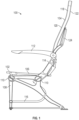
- a passenger seat assembly 100 may include one or more seat bases 102 and one or more seat backs 104.
- the number of seat bases 102 and/or seat backs 104 should not be considered limiting on the current disclosure.
- the number of seat backs 104 correspond with the number of passengers that the passenger seat is capable of carrying.
- the passenger seat assembly 100 is capable of carrying one passenger, and accordingly has one seat back 104.
- the passenger seat assembly 100 may be capable of carrying any desired number of passengers, such as one passenger, two passengers, three passengers, four passengers, or any other desired number of passengers.
- the passenger seat assembly 100 can likewise have any desired number of corresponding seat backs 104.
- the seat base 102 of the passenger seat assembly 100 generally includes a leg assembly 108 and at least one base frame tube 110.
- the base frame tube 110 is a primary tubular frame component of the passenger seat assembly 100, meaning that is one of the elements on the primary load path from the passenger (seat belt) to the aircraft floor (tracks). Secondary frame components are not on the primary load path but may provide other structural support. Whereas base frame tubes 110 are generally straight, other frame components such as secondary frame components may be bent into various shapes in one or more planes as discussed in detail below.
- the seat base 102 may also include a support frame 106, an armrest 112, a divider 114, a luggage bar 116, or other components. Cushioning (not illustrated) may be provided on any of the components of the seat base 102.
- the seat back 104 is connected to the seat base 102, and is often pivotable relative to the seat base 102 such that the seat back 104 can be positioned in various positions such as a taxi-takeoff-landing (TTL) position, a reclined position, etc.
- the seat back 104 includes a frame component 118 having a forward side 120 and an aft side 122.
- other components of the passenger seat assembly 100 such as a tray table 124, an in-flight entertainment monitor, or various other components may be supported on the seat back 104.
- Cushioning (not illustrated) may be provided on any of the components of the seat back 104.
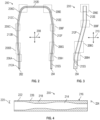
- Figures 2-4 illustrate an example of a tubular frame component 200.
- the tubular frame component 200 is illustrated as a frame component of the seat back 104, although in other examples the tubular frame component 200 may be utilized as various other frame components of the seat base 102 and/or the seat back 104 of the passenger seat assembly 100 as desired.
- the tubular frame component 200 may be constructed from various suitable materials including, but not limited to aluminum, stainless steel, other metallic materials, composite materials, and/or other suitable materials.
- the tubular frame component 200 may be formed by extrusion or other suitable processes as desired.
- the tubular frame component 200 includes a first end 202 and a second end 204. As discussed in detail below, between the first end 202 and the second end 204, the tubular frame component 200 includes a first portion having a first wall thickness and a second portion having a second wall thickness that is different from the first wall thickness. In the example of Figures 2-4 , the first end 202 and the second end 204 may be attached to the seat base 102 through various suitable mechanisms. Between the first end 202 and the second end 204, the tubular frame component 200 includes one or more bent portions 206 that bend the tubular frame component 200 at a non-zero angle within one or more planes.
- the tubular frame component 200 includes eight bent portions 206A-H; bent portions 206A-H bend the tubular frame component 200 at non-zero angles within a first plane 208 (see Figure 2 ), and bent portions 206A-C and 206F-H bend the tubular frame component at non-zero angles within a second plane 210 (see Figure 3 ).
- the bent portions 206 may be adjacent to non-bent portions of the tubular frame component 200 and/or other bent portions 206.
- a non-bent portion 212 of the tubular frame component 200 is adjacent to at least one bent portion 206.
- the tubular frame component 200 includes seven non-bent portions 212A-G.
- the number of non-bent portions 212 should not be considered limiting on the current disclosure, and in some examples, the non-bent portions may be omitted from the tubular frame component 200.
- the tubular frame component 200 includes an inner surface 214 and an outer surface 216.
- a distance from the inner surface 214 to the outer surface 216 is a wall thickness of the tubular frame component 200, and the tubular frame component 200 has a variable wall thickness such that at least two portions having a different wall thicknesses.
- a first portion 218 has a first wall thickness 220 and a second portion 222 has a second wall thickness 224 that is less than the first wall thickness 220.
- the outer surface 216 has a constant outer diameter and the inner surface 214 has a variable inner diameter such that the tubular frame component 200 has a variable wall thickness.
- a transition portion 226 having an increasing or decreasing wall thickness is provided between the first portion 218 and the second portion 222.
- the wall thickness of the tubular frame component may be from about 0.15 mm to about 6.35 mm ( about 0.006 inches to about 0.25 inches). In certain embodiments, the wall thickness of the tubular frame component may be from about 0.254 mm to about 2.032 mm ( about 0.01 inches to about 0.08 inches).
- the tubular frame components 200 may have various patterns or arrangements of wall thicknesses as desired, and the wall thickness pattern illustrated in Figure 4 should not be considered limiting on the current disclosure.
- the tubular frame component 200 may have a variable wall thickness such that the wall thickness of one of the bent portions 206 (e.g., bent portion 206A) is greater than the thickness of one of the non-bent portions 212 (e.g., non-bent portion 212A).
- the tubular frame component 200 may have a variable wall thickness such that the thickness of one of the bent portions (e.g., bent portion 206A) is greater than the thickness of another one of the bent portions (e.g., bent portion 206D).
- the tubular frame component 200 may have a variable wall thickness such that a plurality of wall thicknesses are utilized.
- the wall thickness of the bent portion 206D may be less than the wall thickness of the bent portion 206C
- the wall thickness of the bent portion 206C may be less than the wall thickness of the bent portion 206A.
- the wall thickness of the non-bent portion 212D may be less than the wall thickness of the non-bent portion 212C, and the wall thickness of the non-bent portion 212C may be less than the wall thickness of the bent portion 206D.
- Various other patterns or arrangements of wall thicknesses may be utilized as desired.
- the tubular frame component 200 with the variable wall thickness has increased formability and manufacturability into various shapes and configurations as desired while meeting various mechanical requirements (e.g., strength) at a lower overall weight.
- portions of the tubular frame component 200 subject to relatively high strains e.g., bent portions, portions connecting to other seat components, etc.
- portions subject to less strains e.g., non-bent portions, portions not connected to other seat components, etc.
- the increased formability may allow for more complex shaping of the tubular frame component 200 without failure, and may also allow for materials to be used as the tubular frame component 200 (e.g., high strength aluminum alloys) that previously could not be used.
- the decreased weight of the tubular frame component 200 may provide cost savings and also weight savings to the overall passenger seat.
Landscapes
- Engineering & Computer Science (AREA)
- Aviation & Aerospace Engineering (AREA)
- Transportation (AREA)
- Mechanical Engineering (AREA)
- Chair Legs, Seat Parts, And Backrests (AREA)
- Seats For Vehicles (AREA)
Claims (7)
- Ensemble formant siège de passager (100) comprenant :une assise (102) ; etun dossier relié à l'assise (102) et comprenant un cadre, le cadre comprenant un composant de cadre tubulaire (200) incluant une surface intérieure (214) et une surface extérieure (216), la surface extérieure (216) ayant un diamètre extérieur constant et la surface intérieure (212) ayant un diamètre intérieur variable de telle sorte qu'une première partie (218) du composant de cadre tubulaire (200) ait une première épaisseur de paroi (220) et une deuxième partie (222) du composant de cadre tubulaire (200) ait une deuxième épaisseur de paroi (224) qui est différente de la première épaisseur de paroi (220),caractérisé en ce que le composant de cadre tubulaire (200) comprend en outre une partie de transition (226) qui a une épaisseur de paroi croissante ou décroissante, ladite partie de transition (226) étant disposée entre la première partie (218) et la deuxième partie (222),le composant de cadre tubulaire (200) comprenant une première extrémité (202) et une deuxième extrémité (204), le composant de cadre tubulaire (200) comprenant, entre la première extrémité (202) et la deuxième extrémité (204), huit parties incurvées (206A-H) incurvant le composant de cadre tubulaire (200) suivant des angles non nuls dans un premier plan (208), et six parties incurvées (206AC ; 206F-H) incurvant le composant de cadre tubulaire suivant des angles non nuls dans un deuxième plan (210).
- Ensemble formant siège de passager selon la revendication 1, caractérisé en ce que la première partie (218) du composant de cadre tubulaire (200) est une partie incurvée (206) incurvant le cadre suivant un angle non nul dans le premier plan défini par le dossier.
- Ensemble formant siège de passager selon la revendication 2, caractérisé en ce que la deuxième partie (222) du composant de cadre tubulaire (200) est une deuxième partie incurvée incurvant le cadre suivant un angle non nul dans le deuxième plan défini par le dossier.
- Ensemble formant siège de passager selon l'une quelconque des revendications 1 à 3, caractérisé en ce que le dossier comprend une extrémité supérieure et une extrémité inférieure, la première partie (218) formant au moins partiellement l'extrémité inférieure du dossier, et la deuxième partie (222) formant au moins partiellement l'extrémité supérieure du dossier.
- Ensemble formant siège de passager selon l'une quelconque des revendications 1 à 4, caractérisé en ce que le composant de cadre tubulaire (200) comprend en outre une troisième partie entre la première partie (218) et la deuxième partie (222), et la troisième partie du composant de cadre tubulaire (200) ayant une troisième épaisseur de paroi qui est supérieure à la première épaisseur de paroi (220) et inférieure à la deuxième épaisseur de paroi (224).
- Ensemble formant siège de passager selon l'une quelconque des revendications 1 à 5, caractérisé en ce que la première épaisseur de paroi (220) et la deuxième épaisseur de paroi (224) sont comprises entre environ 0,15 mm et environ 6,35 mm (environ 0,006 pouce et environ 0,25 pouce).
- Ensemble formant siège de passager selon l'une quelconque des revendications 1 à 6, caractérisé en ce que le composant de cadre tubulaire (200) comprend l'un au moins parmi l'aluminium, le magnésium, le titane ou l'acier.
Applications Claiming Priority (1)
| Application Number | Priority Date | Filing Date | Title |
|---|---|---|---|
| PCT/US2019/034717 WO2020242484A1 (fr) | 2019-05-30 | 2019-05-30 | Composant de cadre à épaisseur de paroi variable |
Publications (2)
| Publication Number | Publication Date |
|---|---|
| EP3976473A1 EP3976473A1 (fr) | 2022-04-06 |
| EP3976473B1 true EP3976473B1 (fr) | 2024-11-27 |
Family
ID=66913036
Family Applications (1)
| Application Number | Title | Priority Date | Filing Date |
|---|---|---|---|
| EP19731503.9A Active EP3976473B1 (fr) | 2019-05-30 | 2019-05-30 | Composant de cadre à épaisseur de paroi variable |
Country Status (3)
| Country | Link |
|---|---|
| US (1) | US11873105B2 (fr) |
| EP (1) | EP3976473B1 (fr) |
| WO (1) | WO2020242484A1 (fr) |
Families Citing this family (1)
| Publication number | Priority date | Publication date | Assignee | Title |
|---|---|---|---|---|
| US12503237B2 (en) * | 2021-03-12 | 2025-12-23 | Safran Seats Usa Llc | Non-uniform tubes for aircraft furniture |
Citations (2)
| Publication number | Priority date | Publication date | Assignee | Title |
|---|---|---|---|---|
| US20060201227A1 (en) * | 2004-10-01 | 2006-09-14 | Copperweld Canada Inc. | Vehicle structural components made from tubular members and method therefor |
| US20100289318A1 (en) * | 2009-04-08 | 2010-11-18 | Gary Tien Le | Vehicle seat tubing having variable wall thickness |
Family Cites Families (14)
| Publication number | Priority date | Publication date | Assignee | Title |
|---|---|---|---|---|
| US5362132A (en) * | 1991-02-22 | 1994-11-08 | Hoover Universal, Inc. | Vehicle seat assembly with structural seat back to accommodate seat belt loads applied to seat back |
| FR2753935B1 (fr) * | 1996-10-02 | 1998-12-04 | Faure Bertrand Equipements Sa | Procede pour realiser un siege de vehicule, et siege realise selon ce procede |
| FR2832959B1 (fr) * | 2001-12-04 | 2004-02-13 | Faurecia Sieges Automobile | Structure d'element de siege pour vehicule et procede de fabrication d'une telle structure |
| FR2869849B1 (fr) * | 2004-05-10 | 2006-07-28 | Faurecia Sieges Automobile | Siege de vehicule |
| DE102004035454B4 (de) * | 2004-07-22 | 2015-02-26 | Robert Bosch Gmbh | Trägerelement |
| EP2303484B1 (fr) | 2008-06-03 | 2018-01-03 | Johnson Controls Technology Company | Armature de siège - tubes sur mesure |
| CN102481872A (zh) * | 2009-08-04 | 2012-05-30 | 江森自控科技公司 | 具有冲击负载传递结构的座椅组件 |
| WO2016128524A1 (fr) * | 2015-02-11 | 2016-08-18 | Composite Designs EU GmbH | Ensemble siège passager d'aéronef léger |
| JP6614638B2 (ja) * | 2015-05-12 | 2019-12-04 | 株式会社タチエス | シートフレーム |
| DE102016102707A1 (de) * | 2016-02-16 | 2017-08-17 | Recaro Aircraft Seating Gmbh & Co. Kg | Flugzeugsitzvorrichtung |
| JP6617063B2 (ja) * | 2016-03-16 | 2019-12-04 | 株式会社タチエス | 車両用シート |
| EP3481721B1 (fr) * | 2016-07-07 | 2024-04-10 | Safran Seats USA LLC | Composants de siège composites |
| WO2019017834A1 (fr) * | 2017-07-19 | 2019-01-24 | ST Engineering Aerospace Ltd. | Dossier pour un siège de passager |
| DE102019135393A1 (de) * | 2019-12-20 | 2021-06-24 | Recaro Aircraft Seating Gmbh & Co. Kg | Flugzeugsitzvorrichtung, Flugzeugsitz, Verfahren zur Herstellung der Flugzeugsitzvorrichtung und Baukastensystem |
-
2019
- 2019-05-30 WO PCT/US2019/034717 patent/WO2020242484A1/fr not_active Ceased
- 2019-05-30 US US17/610,667 patent/US11873105B2/en active Active
- 2019-05-30 EP EP19731503.9A patent/EP3976473B1/fr active Active
Patent Citations (2)
| Publication number | Priority date | Publication date | Assignee | Title |
|---|---|---|---|---|
| US20060201227A1 (en) * | 2004-10-01 | 2006-09-14 | Copperweld Canada Inc. | Vehicle structural components made from tubular members and method therefor |
| US20100289318A1 (en) * | 2009-04-08 | 2010-11-18 | Gary Tien Le | Vehicle seat tubing having variable wall thickness |
Also Published As
| Publication number | Publication date |
|---|---|
| EP3976473A1 (fr) | 2022-04-06 |
| WO2020242484A1 (fr) | 2020-12-03 |
| US11873105B2 (en) | 2024-01-16 |
| US20220242576A1 (en) | 2022-08-04 |
Similar Documents
| Publication | Publication Date | Title |
|---|---|---|
| EP3152114B1 (fr) | Element structurale hybride | |
| EP4200213B1 (fr) | Ensemble structurel pour siège passager et procédés associés | |
| WO2013109751A1 (fr) | Siège passager | |
| CN103201174A (zh) | 乘客座椅组件及其多个方面 | |
| US20230331389A1 (en) | Configurable cabin attendant seat | |
| EP3129290B1 (fr) | Unité de siège limitant le risque de blessures à la tête | |
| EP3887254B1 (fr) | Sièges de classe affaires pour un véhicule de transport de passagers | |
| EP3071479B1 (fr) | Siège de passager | |
| EP3000733B1 (fr) | Canapé d'aéronef convertible en lit | |
| US11518281B2 (en) | Light weight metal back with extra living space | |
| EP3976473B1 (fr) | Composant de cadre à épaisseur de paroi variable | |
| US11760491B1 (en) | Two-piece machine leg assembly for passenger seats | |
| US11117502B2 (en) | Variable section bench for seat | |
| EP4328134B1 (fr) | Absorbeur d'énergie pour barre de bagages |
Legal Events
| Date | Code | Title | Description |
|---|---|---|---|
| STAA | Information on the status of an ep patent application or granted ep patent |
Free format text: STATUS: UNKNOWN |
|
| STAA | Information on the status of an ep patent application or granted ep patent |
Free format text: STATUS: THE INTERNATIONAL PUBLICATION HAS BEEN MADE |
|
| PUAI | Public reference made under article 153(3) epc to a published international application that has entered the european phase |
Free format text: ORIGINAL CODE: 0009012 |
|
| STAA | Information on the status of an ep patent application or granted ep patent |
Free format text: STATUS: REQUEST FOR EXAMINATION WAS MADE |
|
| 17P | Request for examination filed |
Effective date: 20211206 |
|
| AK | Designated contracting states |
Kind code of ref document: A1 Designated state(s): AL AT BE BG CH CY CZ DE DK EE ES FI FR GB GR HR HU IE IS IT LI LT LU LV MC MK MT NL NO PL PT RO RS SE SI SK SM TR |
|
| DAV | Request for validation of the european patent (deleted) | ||
| DAX | Request for extension of the european patent (deleted) | ||
| STAA | Information on the status of an ep patent application or granted ep patent |
Free format text: STATUS: EXAMINATION IS IN PROGRESS |
|
| 17Q | First examination report despatched |
Effective date: 20230622 |
|
| GRAP | Despatch of communication of intention to grant a patent |
Free format text: ORIGINAL CODE: EPIDOSNIGR1 |
|
| STAA | Information on the status of an ep patent application or granted ep patent |
Free format text: STATUS: GRANT OF PATENT IS INTENDED |
|
| INTG | Intention to grant announced |
Effective date: 20240709 |
|
| GRAS | Grant fee paid |
Free format text: ORIGINAL CODE: EPIDOSNIGR3 |
|
| GRAA | (expected) grant |
Free format text: ORIGINAL CODE: 0009210 |
|
| STAA | Information on the status of an ep patent application or granted ep patent |
Free format text: STATUS: THE PATENT HAS BEEN GRANTED |
|
| AK | Designated contracting states |
Kind code of ref document: B1 Designated state(s): AL AT BE BG CH CY CZ DE DK EE ES FI FR GB GR HR HU IE IS IT LI LT LU LV MC MK MT NL NO PL PT RO RS SE SI SK SM TR |
|
| REG | Reference to a national code |
Ref country code: GB Ref legal event code: FG4D |
|
| REG | Reference to a national code |
Ref country code: CH Ref legal event code: EP |
|
| REG | Reference to a national code |
Ref country code: DE Ref legal event code: R096 Ref document number: 602019062564 Country of ref document: DE |
|
| REG | Reference to a national code |
Ref country code: IE Ref legal event code: FG4D |
|
| REG | Reference to a national code |
Ref country code: LT Ref legal event code: MG9D |
|
| REG | Reference to a national code |
Ref country code: NL Ref legal event code: MP Effective date: 20241127 |
|
| PG25 | Lapsed in a contracting state [announced via postgrant information from national office to epo] |
Ref country code: HR Free format text: LAPSE BECAUSE OF FAILURE TO SUBMIT A TRANSLATION OF THE DESCRIPTION OR TO PAY THE FEE WITHIN THE PRESCRIBED TIME-LIMIT Effective date: 20241127 Ref country code: IS Free format text: LAPSE BECAUSE OF FAILURE TO SUBMIT A TRANSLATION OF THE DESCRIPTION OR TO PAY THE FEE WITHIN THE PRESCRIBED TIME-LIMIT Effective date: 20250327 Ref country code: PT Free format text: LAPSE BECAUSE OF FAILURE TO SUBMIT A TRANSLATION OF THE DESCRIPTION OR TO PAY THE FEE WITHIN THE PRESCRIBED TIME-LIMIT Effective date: 20250327 |
|
| PG25 | Lapsed in a contracting state [announced via postgrant information from national office to epo] |
Ref country code: FI Free format text: LAPSE BECAUSE OF FAILURE TO SUBMIT A TRANSLATION OF THE DESCRIPTION OR TO PAY THE FEE WITHIN THE PRESCRIBED TIME-LIMIT Effective date: 20241127 Ref country code: NL Free format text: LAPSE BECAUSE OF FAILURE TO SUBMIT A TRANSLATION OF THE DESCRIPTION OR TO PAY THE FEE WITHIN THE PRESCRIBED TIME-LIMIT Effective date: 20241127 |
|
| REG | Reference to a national code |
Ref country code: AT Ref legal event code: MK05 Ref document number: 1745493 Country of ref document: AT Kind code of ref document: T Effective date: 20241127 |
|
| PG25 | Lapsed in a contracting state [announced via postgrant information from national office to epo] |
Ref country code: BG Free format text: LAPSE BECAUSE OF FAILURE TO SUBMIT A TRANSLATION OF THE DESCRIPTION OR TO PAY THE FEE WITHIN THE PRESCRIBED TIME-LIMIT Effective date: 20241127 |
|
| PG25 | Lapsed in a contracting state [announced via postgrant information from national office to epo] |
Ref country code: ES Free format text: LAPSE BECAUSE OF FAILURE TO SUBMIT A TRANSLATION OF THE DESCRIPTION OR TO PAY THE FEE WITHIN THE PRESCRIBED TIME-LIMIT Effective date: 20241127 |
|
| PG25 | Lapsed in a contracting state [announced via postgrant information from national office to epo] |
Ref country code: NO Free format text: LAPSE BECAUSE OF FAILURE TO SUBMIT A TRANSLATION OF THE DESCRIPTION OR TO PAY THE FEE WITHIN THE PRESCRIBED TIME-LIMIT Effective date: 20250227 |
|
| PG25 | Lapsed in a contracting state [announced via postgrant information from national office to epo] |
Ref country code: GR Free format text: LAPSE BECAUSE OF FAILURE TO SUBMIT A TRANSLATION OF THE DESCRIPTION OR TO PAY THE FEE WITHIN THE PRESCRIBED TIME-LIMIT Effective date: 20250228 Ref country code: LV Free format text: LAPSE BECAUSE OF FAILURE TO SUBMIT A TRANSLATION OF THE DESCRIPTION OR TO PAY THE FEE WITHIN THE PRESCRIBED TIME-LIMIT Effective date: 20241127 Ref country code: AT Free format text: LAPSE BECAUSE OF FAILURE TO SUBMIT A TRANSLATION OF THE DESCRIPTION OR TO PAY THE FEE WITHIN THE PRESCRIBED TIME-LIMIT Effective date: 20241127 |
|
| PG25 | Lapsed in a contracting state [announced via postgrant information from national office to epo] |
Ref country code: PL Free format text: LAPSE BECAUSE OF FAILURE TO SUBMIT A TRANSLATION OF THE DESCRIPTION OR TO PAY THE FEE WITHIN THE PRESCRIBED TIME-LIMIT Effective date: 20241127 |
|
| PG25 | Lapsed in a contracting state [announced via postgrant information from national office to epo] |
Ref country code: RS Free format text: LAPSE BECAUSE OF FAILURE TO SUBMIT A TRANSLATION OF THE DESCRIPTION OR TO PAY THE FEE WITHIN THE PRESCRIBED TIME-LIMIT Effective date: 20250227 |
|
| PG25 | Lapsed in a contracting state [announced via postgrant information from national office to epo] |
Ref country code: SM Free format text: LAPSE BECAUSE OF FAILURE TO SUBMIT A TRANSLATION OF THE DESCRIPTION OR TO PAY THE FEE WITHIN THE PRESCRIBED TIME-LIMIT Effective date: 20241127 |
|
| PGFP | Annual fee paid to national office [announced via postgrant information from national office to epo] |
Ref country code: DE Payment date: 20250519 Year of fee payment: 7 |
|
| PG25 | Lapsed in a contracting state [announced via postgrant information from national office to epo] |
Ref country code: DK Free format text: LAPSE BECAUSE OF FAILURE TO SUBMIT A TRANSLATION OF THE DESCRIPTION OR TO PAY THE FEE WITHIN THE PRESCRIBED TIME-LIMIT Effective date: 20241127 |
|
| PGFP | Annual fee paid to national office [announced via postgrant information from national office to epo] |
Ref country code: GB Payment date: 20250527 Year of fee payment: 7 |
|
| PG25 | Lapsed in a contracting state [announced via postgrant information from national office to epo] |
Ref country code: EE Free format text: LAPSE BECAUSE OF FAILURE TO SUBMIT A TRANSLATION OF THE DESCRIPTION OR TO PAY THE FEE WITHIN THE PRESCRIBED TIME-LIMIT Effective date: 20241127 |
|
| PGFP | Annual fee paid to national office [announced via postgrant information from national office to epo] |
Ref country code: FR Payment date: 20250526 Year of fee payment: 7 |
|
| PG25 | Lapsed in a contracting state [announced via postgrant information from national office to epo] |
Ref country code: RO Free format text: LAPSE BECAUSE OF FAILURE TO SUBMIT A TRANSLATION OF THE DESCRIPTION OR TO PAY THE FEE WITHIN THE PRESCRIBED TIME-LIMIT Effective date: 20241127 |
|
| PG25 | Lapsed in a contracting state [announced via postgrant information from national office to epo] |
Ref country code: SK Free format text: LAPSE BECAUSE OF FAILURE TO SUBMIT A TRANSLATION OF THE DESCRIPTION OR TO PAY THE FEE WITHIN THE PRESCRIBED TIME-LIMIT Effective date: 20241127 |
|
| PG25 | Lapsed in a contracting state [announced via postgrant information from national office to epo] |
Ref country code: CZ Free format text: LAPSE BECAUSE OF FAILURE TO SUBMIT A TRANSLATION OF THE DESCRIPTION OR TO PAY THE FEE WITHIN THE PRESCRIBED TIME-LIMIT Effective date: 20241127 |
|
| PG25 | Lapsed in a contracting state [announced via postgrant information from national office to epo] |
Ref country code: IT Free format text: LAPSE BECAUSE OF FAILURE TO SUBMIT A TRANSLATION OF THE DESCRIPTION OR TO PAY THE FEE WITHIN THE PRESCRIBED TIME-LIMIT Effective date: 20241127 |
|
| REG | Reference to a national code |
Ref country code: DE Ref legal event code: R097 Ref document number: 602019062564 Country of ref document: DE |
|
| PG25 | Lapsed in a contracting state [announced via postgrant information from national office to epo] |
Ref country code: SE Free format text: LAPSE BECAUSE OF FAILURE TO SUBMIT A TRANSLATION OF THE DESCRIPTION OR TO PAY THE FEE WITHIN THE PRESCRIBED TIME-LIMIT Effective date: 20241127 |
|
| PLBE | No opposition filed within time limit |
Free format text: ORIGINAL CODE: 0009261 |
|
| STAA | Information on the status of an ep patent application or granted ep patent |
Free format text: STATUS: NO OPPOSITION FILED WITHIN TIME LIMIT |
|
| REG | Reference to a national code |
Ref country code: CH Ref legal event code: L10 Free format text: ST27 STATUS EVENT CODE: U-0-0-L10-L00 (AS PROVIDED BY THE NATIONAL OFFICE) Effective date: 20251008 |
|
| 26N | No opposition filed |
Effective date: 20250828 |
|
| REG | Reference to a national code |
Ref country code: CH Ref legal event code: H13 Free format text: ST27 STATUS EVENT CODE: U-0-0-H10-H13 (AS PROVIDED BY THE NATIONAL OFFICE) Effective date: 20251223 |
|
| PG25 | Lapsed in a contracting state [announced via postgrant information from national office to epo] |
Ref country code: LU Free format text: LAPSE BECAUSE OF NON-PAYMENT OF DUE FEES Effective date: 20250530 |
|
| PG25 | Lapsed in a contracting state [announced via postgrant information from national office to epo] |
Ref country code: CH Free format text: LAPSE BECAUSE OF NON-PAYMENT OF DUE FEES Effective date: 20250531 |
|
| REG | Reference to a national code |
Ref country code: BE Ref legal event code: MM Effective date: 20250531 |
|
| PG25 | Lapsed in a contracting state [announced via postgrant information from national office to epo] |
Ref country code: MC Free format text: LAPSE BECAUSE OF FAILURE TO SUBMIT A TRANSLATION OF THE DESCRIPTION OR TO PAY THE FEE WITHIN THE PRESCRIBED TIME-LIMIT Effective date: 20241127 |
|
| PG25 | Lapsed in a contracting state [announced via postgrant information from national office to epo] |
Ref country code: IE Free format text: LAPSE BECAUSE OF NON-PAYMENT OF DUE FEES Effective date: 20250530 |
|
| PG25 | Lapsed in a contracting state [announced via postgrant information from national office to epo] |
Ref country code: BE Free format text: LAPSE BECAUSE OF NON-PAYMENT OF DUE FEES Effective date: 20250531 |