EP3976977B1 - Élément de liaison - Google Patents
Élément de liaison Download PDFInfo
- Publication number
- EP3976977B1 EP3976977B1 EP20726382.3A EP20726382A EP3976977B1 EP 3976977 B1 EP3976977 B1 EP 3976977B1 EP 20726382 A EP20726382 A EP 20726382A EP 3976977 B1 EP3976977 B1 EP 3976977B1
- Authority
- EP
- European Patent Office
- Prior art keywords
- connecting element
- section
- regions
- shank
- ribs
- Prior art date
- Legal status (The legal status is an assumption and is not a legal conclusion. Google has not performed a legal analysis and makes no representation as to the accuracy of the status listed.)
- Active
Links
Images




Classifications
-
- F—MECHANICAL ENGINEERING; LIGHTING; HEATING; WEAPONS; BLASTING
- F16—ENGINEERING ELEMENTS AND UNITS; GENERAL MEASURES FOR PRODUCING AND MAINTAINING EFFECTIVE FUNCTIONING OF MACHINES OR INSTALLATIONS; THERMAL INSULATION IN GENERAL
- F16B—DEVICES FOR FASTENING OR SECURING CONSTRUCTIONAL ELEMENTS OR MACHINE PARTS TOGETHER, e.g. NAILS, BOLTS, CIRCLIPS, CLAMPS, CLIPS OR WEDGES; JOINTS OR JOINTING
- F16B19/00—Bolts without screw-thread; Pins, including deformable elements; Rivets
- F16B19/02—Bolts or sleeves for positioning of machine parts, e.g. notched taper pins, fitting pins, sleeves, eccentric positioning rings
-
- F—MECHANICAL ENGINEERING; LIGHTING; HEATING; WEAPONS; BLASTING
- F16—ENGINEERING ELEMENTS AND UNITS; GENERAL MEASURES FOR PRODUCING AND MAINTAINING EFFECTIVE FUNCTIONING OF MACHINES OR INSTALLATIONS; THERMAL INSULATION IN GENERAL
- F16B—DEVICES FOR FASTENING OR SECURING CONSTRUCTIONAL ELEMENTS OR MACHINE PARTS TOGETHER, e.g. NAILS, BOLTS, CIRCLIPS, CLAMPS, CLIPS OR WEDGES; JOINTS OR JOINTING
- F16B33/00—Features common to bolt and nut
- F16B33/002—Means for preventing rotation of screw-threaded elements
-
- F—MECHANICAL ENGINEERING; LIGHTING; HEATING; WEAPONS; BLASTING
- F16—ENGINEERING ELEMENTS AND UNITS; GENERAL MEASURES FOR PRODUCING AND MAINTAINING EFFECTIVE FUNCTIONING OF MACHINES OR INSTALLATIONS; THERMAL INSULATION IN GENERAL
- F16B—DEVICES FOR FASTENING OR SECURING CONSTRUCTIONAL ELEMENTS OR MACHINE PARTS TOGETHER, e.g. NAILS, BOLTS, CIRCLIPS, CLAMPS, CLIPS OR WEDGES; JOINTS OR JOINTING
- F16B35/00—Screw-bolts; Stay-bolts; Screw-threaded studs; Screws; Set screws
- F16B35/04—Screw-bolts; Stay-bolts; Screw-threaded studs; Screws; Set screws with specially-shaped head or shaft in order to fix the bolt on or in an object
- F16B35/06—Specially-shaped heads
-
- F—MECHANICAL ENGINEERING; LIGHTING; HEATING; WEAPONS; BLASTING
- F16—ENGINEERING ELEMENTS AND UNITS; GENERAL MEASURES FOR PRODUCING AND MAINTAINING EFFECTIVE FUNCTIONING OF MACHINES OR INSTALLATIONS; THERMAL INSULATION IN GENERAL
- F16B—DEVICES FOR FASTENING OR SECURING CONSTRUCTIONAL ELEMENTS OR MACHINE PARTS TOGETHER, e.g. NAILS, BOLTS, CIRCLIPS, CLAMPS, CLIPS OR WEDGES; JOINTS OR JOINTING
- F16B35/00—Screw-bolts; Stay-bolts; Screw-threaded studs; Screws; Set screws
- F16B35/005—Set screws; Locking means therefor
-
- F—MECHANICAL ENGINEERING; LIGHTING; HEATING; WEAPONS; BLASTING
- F16—ENGINEERING ELEMENTS AND UNITS; GENERAL MEASURES FOR PRODUCING AND MAINTAINING EFFECTIVE FUNCTIONING OF MACHINES OR INSTALLATIONS; THERMAL INSULATION IN GENERAL
- F16B—DEVICES FOR FASTENING OR SECURING CONSTRUCTIONAL ELEMENTS OR MACHINE PARTS TOGETHER, e.g. NAILS, BOLTS, CIRCLIPS, CLAMPS, CLIPS OR WEDGES; JOINTS OR JOINTING
- F16B37/00—Nuts or like thread-engaging members
- F16B37/04—Devices for fastening nuts to surfaces, e.g. sheets, plates
- F16B37/048—Non-releasable devices
Definitions
- the invention relates to a connecting element for pressing or embedding in a component with a shaft which extends along a central longitudinal axis of the connecting element, wherein the shaft is provided with ribs extending in the radial direction to the shaft and wherein the shaft has a polylobular cross-section at least in sections, wherein the circumference of the polylobular cross-section is convexly curved over its entire length, in particular is arranged between a circumcircle and an incircle and, viewed in the radial direction, has regions with a larger radius or smaller curvature and regions with a smaller radius or larger curvature.
- the shaft can have a polygonal cross-section with rounded corners.
- the invention is intended to improve a connecting element for pressing or embedding in a component with regard to anchoring in the component.
- a connecting element with the features of claim 1 is provided for this purpose.
- a connecting element for pressing or embedding in a component with a shaft that extends along a central longitudinal axis of the connecting element wherein the shaft is provided with ribs extending in the radial direction to the shaft and wherein the shaft has a polylobular cross-section at least in sections, wherein the circumference of the polylobular cross-section is convexly curved over its entire length, in particular is arranged between a circumcircle and an incircle, and, seen in the radial direction, has areas with a larger radius or smaller curvature and areas with a smaller radius or larger curvature, an angular position of the areas with a smaller radius and the areas with a larger radius changes along the shaft, seen along the central longitudinal axis.
- the polylobular cross-section of the shaft twists, seen over the length of the shaft.
- the areas with a smaller radius extending to the circumference of the polylobular cross-section are offset from one another.
- These outwardly projecting areas with a smaller radius are primarily responsible for anchoring the connecting element in a component.
- the pressing force with conventional connecting elements for pressing in depends to a large extent on the tolerance of the core hole.
- the polylobular cross-section of the shaft is twisted along the shaft axis, for example twisted in a spiral shape.
- the high points of the knurling which are formed by the areas with a small radius of the cross-section, are no longer in line.
- knurls or transverse knurls further back can still take up material that has not yet been pushed away. This can significantly improve the overall filling level of the knurling or the ribs and thus the extrusion force when pressing or embedding in a component. This is particularly the case with components made of aluminum or plastic.
- the ratio of the smaller radius to the larger radius changes with the dimension, i.e. the maximum transverse dimension, of the shaft.
- the angular position of the areas with a smaller radius and the areas with a larger radius changes by a constant amount per unit length along the shaft.
- the polylobular cross-section has n regions with a smaller radius and the angular position changes along the entire length of the shaft by an angle of 360°/n.
- areas with a circular cross-section and a polylobular cross-section alternate along the length of the shaft.
- the shaft in the section of the shaft with a polylobular cross-section, has a polylobular cross-section at every point in this section.
- Both the outer diameter of the shaft and the core diameter of the shaft are polylobular. This allows the shaft with the ribs to be made stable.
- a sectional view of the shaft has a wave-shaped outer contour at every angular position about the central longitudinal axis.
- the wave-shaped outer contour in a cutting plane that contains the central longitudinal axis ensures that the connecting element is securely anchored in the surrounding material. According to the invention, this is achieved over the entire circumference of the connecting element.
- an imaginary line that connects the deepest points or points closest to the central longitudinal axis between two ribs also runs in a wave-shaped manner in this cutting plane.
- the profile depth of the ribs changes by a maximum of 50%.
- a profile depth of the ribs changes by a maximum of 10%, in particular the profile depth is constant.
- the cross-section is designed as a uniform thickness.
- a transverse dimension of the polylobular cross-section measured in the radial direction is therefore always the same, regardless of the angular position. This facilitates the production of the connecting element using rolling tools, in particular rolling dies.
- the cross-section has three regions with a smaller radius or greater curvature and three regions with a larger radius or smaller curvature.
- the cross-section therefore has three outward-projecting areas, namely the areas with a smaller radius or greater curvature, whose vertex lies on the circumference, and the cross-section has three areas with a larger radius or smaller curvature, whose vertex lies on the inscribed circle.
- the areas with a smaller radius and the areas with a larger radius are evenly spaced from one another.
- Such a cross-section can be produced cost-effectively using a rolling process, in particular using rolling dies, with high precision and in large quantities.
- the circumference of the cross section is continuous without corners.
- the ribs run at least partially in the circumferential direction.
- the angular position of the regions with a smaller radius or greater curvature and the regions with a larger radius or smaller curvature changes in the longitudinal direction of the shaft for each rib by approximately 10° to 40°.
- the ribs extend at least partially in the axial direction.
- the ribs run over at least a portion of the length of the shaft in the circumferential direction and the ribs run over at least a portion of the length of the shaft in the axial direction.
- an extremely secure anchoring of the connecting element can be achieved both in the circumferential direction and in the longitudinal direction of the shaft.
- Either a partial area with ribs running in the axial direction or a partial area with ribs running in the circumferential direction can be provided with the polylobular cross-section and the changing angular position of the areas with a smaller radius or larger curvature and the areas with a larger radius or smaller curvature, or both the partial area with ribs in the circumferential direction and the partial area with ribs in the axial direction can have a polylobular cross-section.
- the ribs extend in the circumferential direction over at least a partial region of the length of the shaft, and the angular position of the regions with a smaller radius or greater curvature and the regions with a larger radius or smaller curvature changes alternately in a positive direction and in a negative direction starting from a first rib.
- the direction in which the angular position changes can change from rib to rib or, for example, several ribs can appear one after the other with a change in a positive direction and then one or more ribs with a change in a negative direction.
- alignment of the areas with a larger radius and the areas with a smaller radius over the length of the shaft can either be completely avoided or set so that alignment only occurs again after a larger number of ribs. This can increase the pressing force of the connecting element according to the invention.
- the angular position of the regions with a smaller radius and the regions with a larger radius changes clockwise and/or counterclockwise as viewed along the central longitudinal axis.
- the connecting element is made at least in sections from steel, aluminum, copper or brass.
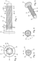
- Fig. 1 shows a connecting element 10 according to the invention in accordance with a first embodiment of the invention.
- the connecting element 10 is intended for pressing or embedding in a component (not shown) and has a shaft 12 which extends along a central longitudinal axis 14 of the connecting element 10.
- a head 16 of the connecting element 10 is provided, which has a larger diameter than the shaft 12.
- the head 16 is designed like a disk.
- the head 16 can be Fig. 1
- the side shown on the left may be provided with a drive formation, but usually no drive formation is provided on the head 16, since the connecting element 10 is intended for pressing or embedding in a component.
- the shaft 12 has a truncated cone-shaped taper 18, which facilitates threading into a core hole.
- the shaft 12 is provided with numerous ribs 20 extending in the radial direction.
- the ribs 20 run in the circumferential direction and each have, as in Fig. 1 can be seen, a triangular cross-section.
- the height of the ribs, which is measured along the central longitudinal axis 14, is the same for all ribs.
- the ribs 20 are each formed in the shape of a truncated cone, with a side with a smaller diameter of each rib 20 facing the free end 18 of the shaft 12, i.e. in the pressing direction of the connecting element 10.
- each rib 20 Towards the side of the head 16, the truncated cone-shaped section of each rib 20 is followed by a significantly shorter section which is approximately perpendicular to the central longitudinal axis 14 and in which a reduction in diameter takes place.
- the diameter of the Fig. 1 left end of each rib and the diameter of the Fig. 1 right-hand end of each rib 20 is approximately the same.
- the shaft 12 has a sawtooth-like outer contour in the area of the ribs 20.
- the shaft 12 can thus be pressed into a core hole of a component. Pulling the shaft 12 out of the core hole of the component is made very difficult by the sawtooth-like design of the outer contour of the shaft 12 with the ribs 20. This is because the ribs 20 can be pulled out of a core hole in Fig. 1 i.e. to the left, into the surrounding material of the wall of the core hole.
- Fig. 2 shows a front view of the connecting element 10 of the Fig. 1 , with the view in Fig. 2 directed to the truncated cone-shaped tapered end 18 of the shaft 12.
- a cross section of the shaft 12 is not circular, but polylobular with three outwardly projecting areas and three areas connecting the outwardly projecting areas.
- Such a cross section can also be referred to as trilobular.
- the cross section of the shaft 12 has a circumference with three areas 22 with a smaller radius or greater curvature, each evenly spaced 120° apart from one another. These areas 22 with a smaller radius form the areas of the circumference of the cross section of the shaft 12 that project in the radial direction.
- areas 24 with a larger radius or smaller curvature are arranged, which are necessarily also evenly spaced from one another, specifically at an angle of 120° to one another. These areas 24 with a larger radius connect the outwardly projecting areas 22 with a smaller radius.
- the circumference of the cross section of the shaft 12 is continuously convexly curved and has no corners or edges.
- the Fig. 2 visible circumference of the shaft 12 corresponds to the cross section in the area of the cutting plane AA in Fig. 1 .
- Fig. 1 the vertices of the areas 22 with a smaller radius on each rib 20 are indicated schematically by means of lines. It can be seen that the areas with a smaller radius 22 change their angular position when viewed in the longitudinal direction of the shaft 12, i.e. in the direction of the central longitudinal axis 14. In the direction from the head 16 to the end 18 of the shaft 12, the cross section of the shaft 12 is rotated a little clockwise with each rib 20.
- the areas 22 with a smaller radius are thus, as Fig. 1 can be seen, arranged in such a way that a line drawn through the regions 22 with a smaller radius forms a spiral around the shaft 12. This is achieved by changing the angular position of the regions 22 with a smaller radius and, as a result, the angular position of the regions 24 with a larger radius by a constant amount from rib 20 to rib 20.
- Fig. 3 shows a view of the section plane AA in Fig. 1 It can be seen that the areas 22 with smaller radius are spaced apart at an angle of 120° and that the Fig. 3 The area 22 shown on the left with a smaller radius forms an angle of 0° to a horizontal axis.
- Fig. 4 shows a view of the section plane BB in Fig. 1 .
- the cutting plane BB is arranged at a distance of 5 x P from the cutting plane AA, i.e. at a distance of five times the height of each rib 20.
- Fig. 4 it can be seen that the Fig. 3
- the area 22 with a smaller radius, which is still on the left, is now rotated downwards by an angle A. This angle A is approximately 50° in the embodiment shown.
- Fig. 4 is also the one from Fig. 3
- the angular position of area 22 in section plane AA can be recognized by blackened areas. Starting from section plane AA in Fig.
- the angular position of the areas 22 with smaller radius and the angular position of the areas 24 with larger radius thus change in the direction of the head 16 at each rib 20 by 10°.
- the angular position of the areas with a smaller radius 22 and the angular position of the areas with a larger radius 24 are then rotated by 50° in an anti-clockwise direction compared to the angular position on the cutting plane AA. Viewed over the entire length of the shaft 12, this results in the helical twisting of the polylobular cross sections of the ribs 20 or the twisting of the polylobular cross sections over the length of the shaft 12.
- Fig. 5 shows an isometric view of the connecting element 10 of the Fig. 1 from above at an angle.
- the vertices of the areas with a smaller radius 22 are again indicated by lines on the individual ribs 20 and overall the spiral twisting of the polylobular cross sections of the ribs 20 can be seen over the length of the shaft 12.
- Fig. 6 shows a connecting element 30 according to the invention in accordance with a further embodiment of the invention.
- the connecting element 30 has a shaft 32 which extends along a central longitudinal axis 14 between a frustoconical end 18 and a head 16.
- the shaft 32 has two sections 34 and 36.
- the shaft 32 is designed in the same way as the shaft 12 of the connecting element 10 of the Fig. 1 .
- the individual ribs 20 each have a polylobular cross-section with three areas 22 with a smaller radius and three areas 24 with a larger radius and the angular position of the areas 22 with a smaller radius and the areas 24 with a larger radius changes in the longitudinal direction of the shaft 32. This can be seen from the areas 22 with a smaller radius marked with lines in Fig. 6 to recognize.
- the section 34 of the shaft 32 has only nine consecutive ribs 20 and then transitions into the section 36, in which ribs 40 are provided that extend in the axial direction.
- the ribs 40 each have a triangular cross-section.
- a cross-section of the shaft 32 in the section 36 is generally circular.
- the outer edges of the ribs 40, which run parallel to the central longitudinal axis 14, are therefore all located on a circle around the central longitudinal axis 14.
- the cross section of the shaft 32 can also be designed in the partial section 36 as polylobular with several areas with a smaller radius and several areas with a larger radius.
- the angular position of the areas with a smaller radius and a larger radius can be constant, so that the shaft in the partial section 36 is polylobular and is cylindrical.
- the angular position of the area with a smaller radius and a larger radius in the longitudinal direction of the shaft 32 can also change in the partial section 36.
- the connecting element 30 is provided with a threaded bolt 42.
- another component can be attached to the threaded bolt 42 and secured, for example, with a nut on the threaded bolt 42.
- the section 36 of the shaft 32 ensures that the connecting element 30 is secured against rotation, i.e. against rotation about the central longitudinal axis 14.
- the section 34 of the shaft 32 ensures, as can be seen from the connecting element 10 of the Fig. 1 explained, for a pull-out protection along the central longitudinal axis 14, in Fig. 6 so to the left.
- Fig. 7 shows an isometric view of the connecting element 30 of the Fig. 6 from above.
- the threaded bolt 42 is in Fig. 7 shown only schematically.
- the position of the areas 22 with a smaller radius on the shaft 32 and especially in the section 34 can be seen.
- the areas 22 with a smaller radius of the individual ribs 20 are not aligned with one another, but are arranged offset from one another as seen in the longitudinal direction of the shaft 32.
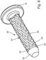
- Fig. 8 shows a connecting element 50 according to a further embodiment of the invention in an isometric view obliquely from above.
- the connecting element 50 has a shaft 52 with numerous ribs 20 running in the circumferential direction.
- the cross section of the ribs 20 corresponds to that already shown in the Fig. 1 explained cross-section.
- the shaft 52 therefore has a sawtooth-like contour.
- the connecting element 50 has a head 16 and a frustoconical free end 18.
- the individual ribs 20 are designed in the same way, as can be seen from the Fig. 1 to 5 Unlike the connecting element 10 of the Fig. 1 is in the connecting element 50 of the Fig. 8 but the change in the angular position of the smaller diameter areas 22 and the larger diameter areas 24 on each rib 20. This is already in Fig. 8 based on the Arrangement of the lines on each rib 20, which mark the position of the vertices of the regions 22 with smaller diameter.
- Fig. 9 shows a side view of the connecting element 50 of the Fig. 8 and Fig. 10 shows a front view of the connecting element 50 of the Fig. 9 , in Fig. 9 i.e. from the right.
- the connecting element 50 of the Fig. 8 to 10 the angular position of the regions 22 with smaller diameter and the regions 24 with larger diameter changes from rib 20 to rib 20 partly clockwise and partly counterclockwise.
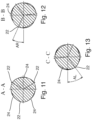
- Fig. 11 shows a view of the section plane AA in Fig. 9 .
- the angular position of the areas 22 with smaller diameter and the areas 24 with larger diameter can be determined at the, see Fig. 9 , first rib 20, which in the direction of the head 16 immediately follows the truncated cone-shaped end 18.
- the Fig. 11 The area 22 with smaller diameter shown on the left lies on a horizontal line.
- Fig. 12 shows a view of the section plane BB in Fig. 9 .
- Fig. 12 shows the angular position of the areas 22 with smaller diameter and the areas 24 with larger diameter on the fifth rib 20 starting from the truncated cone-shaped end 18. It can be seen that the Fig. 12 left-hand region 22 with a smaller diameter is arranged rotated clockwise by an angle AR relative to a horizontal line.
- Fig. 13 shows a view of the section plane CC in Fig. 9 and thereby represents the angular position of the regions 22 with smaller diameter and the angular position of the regions 24 with larger diameter on the sixth rib 20 of the shaft 52 starting from the frustoconical end 18. It is Fig. 13 It can be seen that the Fig. 13 left-hand region 22 with a smaller diameter is rotated counterclockwise by an angle AL relative to a horizontal line.
- the angular position of the areas 22 with a smaller diameter and the areas 24 with a larger diameter therefore changes in the longitudinal direction of the shaft 52, partly clockwise or in a negative direction of rotation, and partly anticlockwise or in a positive direction of rotation.
- areas 22 with a smaller diameter on the individual ribs 20, which protrude in the radial direction are only aligned with one another or lie on top of one another in projection after a comparatively large number of ribs. This means that the pull-out force of the connecting element 50 can be improved even further.
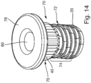
- Fig. 14 shows an isometric view of another connecting element 70 according to the invention.
- the connecting element 70 has a shaft 72 with two sections 74 and 76. In the section 74, ribs 20 are arranged in the circumferential direction, in the section 76, ribs 40 run in the axial direction. A head 78 adjoins the section 76.
- the connecting element 70 is provided with a through hole or through opening 80, see also Fig. 16
- the connecting element 70 can be embedded or pressed into a component and then provides a core hole by means of the through opening 80, into which another component can be inserted, for example, or into which a fastening screw can be screwed.
- Fig. 15 shows a side view of the connecting element 70 of the Fig. 14 .
- a total of five ribs 20 are arranged one behind the other, which, like the ribs 20 of the connecting element 10 of the Fig. 1 and therefore will not be explained again.
- the areas 22 with a smaller radius of the circumference of the shaft 22 in the area of the individual ribs 20 are in Fig. 15 again indicated with lines. It can be seen that the position of the areas 22 with smaller radius and consequently also the position of the areas with larger radius change from rib 20 to rib 20 in a clockwise direction.
- the ribs 40 extending in the axial direction are arranged in the section 76, which lies between the end of the section 74 and the head 16.
- a cross section of the shaft 72 in the section 76 is also polylobular and has three areas with a smaller radius and three areas 24 with a larger radius. In the illustration of the Fig. 15 an area 22 with a smaller radius faces the viewer.
- the shaft 72 also has a polylobular cross-section. This can increase the security against twisting about a central longitudinal axis of the connecting element 70.
- Fig. 16 shows a view of the section plane AA in Fig. 15 .
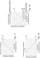
- Fig. 17 shows schematically a section of a circumferential development of a connecting element according to the invention, in which a change or rotation of the angular position of the areas with a smaller radius or larger curvature and the areas with a larger radius or smaller curvature along the shaft takes place in a clockwise direction.
- the individual lines of the development represent ribs 20 running in the circumferential direction and the vertices of areas 22 with a smaller radius are shown by means of vertical lines.
- Fig. 17 It can be seen that the angular position of the areas 22 with smaller radius changes by a constant amount from rib to rib. Viewed along the shaft of a connecting element, this results in a spiral arrangement of the vertices of the areas 22 with smaller radius, as can be seen from the Fig. 1 was explained.
- Fig. 18 shows one of the representations of the Fig. 17 similar representation.
- Fig. 18 shows a change or rotation of the angular position of the areas 22 with a smaller radius in an anti-clockwise direction, whereby the angular position changes by a constant amount from rib 20 to rib 20. Even with such an embodiment, a spiral-shaped sequence of the areas 22 with a smaller radius results over the length of the shaft of a connecting element, as already shown in the Fig. 1 was explained.
- Fig. 19 shows a schematic representation of a section of a peripheral development of a connecting element according to the invention in a Fig. 17 and 18 comparable representation. Based on the Fig. 19 A change or rotation of the angular position of the areas 22 with a smaller radius and the areas 24 with a larger radius in different directions, i.e. clockwise and anti-clockwise, is to be explained.
- a first rib 20 is shown at the free shaft end of the connecting element, based on a comparison with the Fig. 9 this would be the Fig. 9
- the first rib 20 shown on the right follows the truncated cone-shaped end 18.
- This rib 20 has a Fig. 19 centrally arranged region 22 with a smaller radius.
- the regions 22 with a smaller radius, for example the vertices, can also be referred to as high points of the polylobular cross-section.
- the angular position of the area 22 is then changed to the following rib in a clockwise direction.
- the area 22 of the second rib is therefore arranged to the right of the area 22 of the first rib.
- the angular position of the following rib changes counterclockwise, namely in relation to the angular position of the area 22 on the first rib by the same amount of the angle as from the first rib 20 to the second rib 20.
- the area 22 is arranged on the third rib in Fig. 19 thus to the left of the Area 22 is shown on the first rib.
- the angular position is again changed clockwise, by the same amount of angle relative to the angular position on the second rib.
- the angular position is again changed anti-clockwise, by the same amount of angle relative to the position on the third rib.
- the areas 22 with a smaller radius are located on the even-numbered ribs, i.e. on the second rib, the fourth rib, the sixth rib, the eighth rib and the tenth rib. This results in the shape of a spiral running clockwise around the shaft.
- the areas 22 with a smaller radius are located on a spiral rotating anti-clockwise along the shaft.
- Fig. 20 shows a view of another connecting element 10 according to the invention from below.
- the connecting element 10 is essentially the same as the connecting element 10 of the Fig. 1 , whereby the small differences are based on Fig. 24 be explained.
- FIG. 20 Three cutting planes AA, BB and CC are drawn, which are parallel to the central longitudinal axis 14, see also Fig. 1 , and each of which contains the central longitudinal axis, and is therefore radially aligned.
- the cutting axes AA, BB and CC are each arranged at a different angle. There is an angle of 120° between the cutting planes AA and CC. There is an angle of 60° between the cutting planes AA and BB. There is also an angle of 60° between the cutting planes BB and CC.
- the polylobular cross-section of the shaft 12 has three regions with a smaller radius or a larger curvature, each evenly spaced apart by 120°, and between the regions with a smaller radius there are regions with a larger radius or a smaller curvature, which are also evenly spaced apart from one another, the cross-section between the cutting planes AA and CC is repeated three times around the entire circumference of the shaft 12. For the sake of clarity, only the three cutting planes AA, BB and CC are therefore shown.
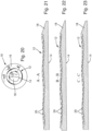
- Fig. 21 shows a section-by-section representation of the view on the section plane AA. It can be seen that the shaft 12 has a wave-shaped outer contour in the section plane AA. It can also be seen that the profile depth of the ribs 20 changes only slightly along the length of the shaft 12. Within the scope of the invention, the profile depth of the ribs 20 should change by a maximum of 50%. In the embodiment shown, the profile depth of the ribs 20 only changes by a maximum of 10%.
- Fig. 22 shows a view of the section plane BB in Fig. 20 .
- the shaft 12 has a wave-shaped outer contour.
- the profile depth of the ribs 20 changes only slightly over the length of the shaft 12 and, in the embodiment shown, by a maximum of about 10%.
- Fig. 23 shows a view of the section plane CC in Fig. 20 . Since the section plane CC is spaced 120° from the section plane AA around the central longitudinal axis 14, the view of the section plane CC corresponds to the view of the section plane AA. In the section plane CC, too, the shaft 12 has a wave-shaped outer contour and the profile height of the ribs 20 changes only slightly over the length of the shaft.
- the shaft 12 has a polylobular cross-section at every point. Both the outer diameter of the shaft and the core diameter of the shaft between the ribs 20 are each polylobular. This is evident from the wave shape of the outer contour of the shaft 12 in the Fig. 21, 22 and 23 and also from the imaginary connecting line of the valleys between the ribs 20, which also has a wave shape. This inner, dashed line, which connects the wave valleys between the ribs 20, illustrates the core diameter. Based on the Fig. 21 to 23 It is clearly visible that both the outer diameter of the shaft 12 and the core diameter show a polylobular course. The outer diameter or the outer contour is determined by the Fig. 21, 22 and 23 drawn, imaginary dashed line which connects the wave crests, thus the outer sections of the ribs 20, with each other.
- Fig. 24 shows a side view of the connecting element of the Fig. 20
- the head 16 and the shaft 12 with the ribs 20 and the truncated cone-shaped taper 18 can be seen.
- the connecting element 10 of the Fig. 24 is, with the exception of the smaller distance between the rib 20 closest to the head 16 and the head 16, identical to the connecting element 10 of the Fig. 1 .
- Identically designed elements of the connecting element 10 are therefore not explained again and bear the same reference numerals.
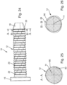
- FIG. 24 Two cutting planes AA and BB are drawn in.
- the cutting plane AA runs through the point of the taper 18 with the largest diameter. This point of the taper 18 with the largest diameter corresponds in its external dimensions to the external dimensions of the ribs 20, but, as already explained, is rotated about the central longitudinal axis compared to the other ribs 20.
- the cutting plane B-B runs through the valley between the point of the taper 18 with the largest diameter and the rib 20 following the taper 18 in the direction of the head 16. In the cutting plane B-B, the course of the core diameter or the transverse dimension of the shaft 12 between two ribs 20 can thus be seen.
- the dimensions of the shaft 12 in the cutting plane B-B correspond in terms of their size to the dimensions of the shaft 12 between each two ribs 20.
- the cross-section in the cutting plane B-B is rotated about the central longitudinal axis 14 compared to the cross-sections between any two ribs 20.
- Fig. 25 shows a view of the section plane AA in Fig. 24 .
- the view is in the direction of the taper 18. In this direction of view, only the outer diameter or the largest transverse dimensions of the taper 18 can be seen, which is why this position of the cutting plane AA was chosen.
- the cross-section in the section plane AA is polylobular. This is indicated by the solid line in Fig. 25 All ribs 20 have a polylobular cross-section, as in Fig. 25 is shown, only the angular position about the central longitudinal axis 14 changes, as discussed in detail above.
- FIG. 25 an imaginary enveloping circle 80, which was entered by means of a dashed line. Furthermore, an imaginary pen circle or inner circle 82 is shown, which is also indicated by a dashed line. As already described, three areas with a larger radius and smaller curvature at a distance of 120° around the central longitudinal axis touch the enveloping circle 80 and three areas with a smaller radius and larger curvature touch the pen circle or inner circle 82.
- Fig. 26 shows the view on the section plane BB in Fig. 24 . Based on the Fig. 25 and the Fig. 26 It can be seen that the shaft 12 has a polylobular shape both between the ribs 20 and at the highest points of the ribs 20. In Fig. 26 the outer contour of the taper 18 can also be seen at the point with the largest transverse dimensions. This is shown by means of a solid circle 84. The outer contour in the section plane BB is shown by means of a solid line 86. It is Fig. 26 It can be seen that a profile depth, i.e. a distance in the radial direction starting from the central longitudinal axis 14 between the lines 86 and 84, changes only slightly over the circumference of the shaft 12. In the embodiment shown, the profile depth changes by only about 10%.
- Fig. 26 It is in Fig. 26 It can also be seen that the angular position of the largest transverse dimensions in the section plane BB and the angle of the largest transverse dimensions in the section plane AA, i.e. between the lines 86 and 84, change.
- a largest transverse dimension lies vertically above the central longitudinal axis 14.
- the largest transverse dimension is offset a little to the left or anti-clockwise.
- the angular position of the largest transverse dimensions of the ribs 20 changes from rib to rib.
Landscapes
- Engineering & Computer Science (AREA)
- General Engineering & Computer Science (AREA)
- Mechanical Engineering (AREA)
- Mutual Connection Of Rods And Tubes (AREA)
- Shafts, Cranks, Connecting Bars, And Related Bearings (AREA)
- Connection Of Plates (AREA)
- Golf Clubs (AREA)
- Manufacture Of Motors, Generators (AREA)
- Chairs For Special Purposes, Such As Reclining Chairs (AREA)
Claims (17)
- Élément de liaison (10 ; 30 ; 50 ; 70) destiné à être enfoncé ou enrobé dans un composant, comprenant une tige (12 ; 32 ; 52 ; 72) qui s'étend le long d'un axe longitudinal central (14) de l'élément de liaison (10 ; 30 ; 50 ; 70), la tige (12 ; 32 ; 52 ; 72) étant pourvue de nervures (20) qui s'étendent dans la direction radiale par rapport à la tige (12 ; 32 ; 52 ; 72) et la tige (12 ; 32 ; 52 ; 72) présentant au moins dans certaines portions une section transversale polylobée, la périphérie de la section transversale polylobée étant courbée de manière convexe sur toute sa longueur et possédant, vues dans la direction radiale, des zones (24) de plus grand rayon ou de plus petite courbure et des zones (22) de plus petit rayon ou de plus grande courbure, caractérisé en ce que, vu le long de l'axe longitudinal central (14), une position angulaire des zones (22) de plus petit rayon ou de plus grande courbure et des zones (24) de plus grand rayon ou de plus petite courbure varie le long de la tige (12 ; 32 ; 52 ; 72).
- Élément de liaison selon la revendication 1, caractérisé en ce que la position angulaire des zones (22) de plus petit rayon ou de plus grande courbure et des zones (24) de plus grand rayon ou de plus petite courbure varie d'une valeur constante par unité de longueur le long de la tige (12 ; 32 ; 52 ; 72).
- Élément de liaison selon la revendication 1 ou 2, caractérisé en ce que la section transversale polylobée comprend n zones (22) de plus petit rayon ou de plus grande courbure et en ce que la position angulaire varie d'un angle de 360 degrés/n sur toute la longueur de la tige.
- Élément de liaison selon au moins l'une des revendications précédentes, caractérisé en ce que, vues sur la longueur de la tige, des zones de sections polylobées différentes alternent.
- Élément de liaison selon au moins l'une des revendications précédentes, caractérisé en ce que, vues sur la longueur de la tige, des zones de section transversale circulaire et des zones de section transversale polylobée alternent.
- Élément de liaison selon l'une des revendications précédentes, caractérisé en ce que, dans la portion de la tige (12 ; 32 ; 52 ; 72) ayant une section transversale polylobée, la tige présente une section transversale polylobée en tout point de la portion.
- Élément de liaison selon l'une des revendications précédentes, caractérisé en ce que, dans la portion de la tige (12 ; 32 ; 52 ; 72) à section transversale polylobée, à chaque position angulaire autour de l'axe longitudinal central, une vue en coupe de la tige (12 ; 32 ; 52 ; 72) présente un contour extérieur ondulé et, dans la vue en coupe, une ligne imaginaire qui relie les points les plus bas entre deux nervures (20) suit un tracé ondulé.
- Élément de liaison selon la revendication 7, caractérisé en ce que la position angulaire des zones (22) de plus petit rayon ou de plus grande courbure et des zones (24) de plus grand rayon ou de plus petite courbure varie, dans la direction longitudinale de la tige, de 10° à 40° à chaque nervure.
- Élément de liaison selon l'une des revendications précédentes, caractérisé en ce que dans la portion de la tige (12 ; 32 ; 52 ; 72) à section transversale polylobée, une profondeur de profil des nervures (20) varie au maximum de 50 %, en particulier au maximum de 10 %, et est notamment constante.
- Élément de liaison selon l'une des revendications précédentes, caractérisé en ce que la section transversale est réalisée sous la forme d'une courbe de largeur constante.
- Élément de liaison selon l'une des revendications précédentes, caractérisé en ce que la section transversale comprend trois zones (22) de plus petit rayon ou de plus grande courbure et trois zones (24) de plus grand rayon ou de plus petite courbure.
- Élément de liaison selon l'une des revendications précédentes, caractérisé en ce que le pourtour de la section transversale est réalisé continu sans coins.
- Élément de liaison selon la revendication 11 ou 12, caractérisé en ce que la position angulaire des zones (22) de plus petit rayon ou de plus grande courbure et des zones (24) de plus grand rayon ou de plus petite courbure, vue le long de l'axe longitudinal central (14), varie dans le sens des aiguilles d'une montre et/ou dans le sens inverse des aiguilles d'une montre.
- Élément de liaison selon l'une des revendications précédentes, caractérisé en ce que les nervures (20) suivent un tracé au moins partiellement dans la direction circonférentielle et/ou en ce que les nervures (40) suivent un tracé au moins partiellement dans la direction axiale.
- Élément de liaison selon l'une des revendications précédentes, caractérisé en ce que les nervures (20) suivent un tracé dans la direction circonférentielle sur au moins une zone partielle de la longueur de la tige et en ce que les nervures (40) suivent un tracé dans la direction axiale sur au moins une zone partielle de la longueur de la tige.
- Élément de liaison selon au moins l'une des revendications précédentes, caractérisé en ce que les nervures (20) suivent un tracé dans la direction circonférentielle au moins sur une zone partielle de la longueur de la tige et en ce que la position angulaire des zones (22) de plus petit rayon ou de plus grande courbure et des zones (24) de plus grand rayon ou de plus petite courbure varie en alternance dans la direction positive et dans la direction négative à partir d'une première nervure.
- Élément de liaison selon l'une des revendications précédentes, caractérisé en ce que la position angulaire des zones (22) de plus petit rayon ou de plus grande courbure et des zones (24) de plus grand rayon ou de plus petite courbure varie de 10 degrés à 40 degrés, en particulier de 10 degrés à 20 degrés, par millimètre de longueur de la tige, notamment dans une portion partielle de la tige pourvue de nervures qui suivent un tracé dans la direction axiale.
Applications Claiming Priority (2)
| Application Number | Priority Date | Filing Date | Title |
|---|---|---|---|
| DE102019207681.5A DE102019207681A1 (de) | 2019-05-24 | 2019-05-24 | Verbindungselement |
| PCT/EP2020/063464 WO2020239460A1 (fr) | 2019-05-24 | 2020-05-14 | Élément de liaison |
Publications (2)
| Publication Number | Publication Date |
|---|---|
| EP3976977A1 EP3976977A1 (fr) | 2022-04-06 |
| EP3976977B1 true EP3976977B1 (fr) | 2024-11-06 |
Family
ID=70740631
Family Applications (1)
| Application Number | Title | Priority Date | Filing Date |
|---|---|---|---|
| EP20726382.3A Active EP3976977B1 (fr) | 2019-05-24 | 2020-05-14 | Élément de liaison |
Country Status (8)
| Country | Link |
|---|---|
| US (1) | US11920620B2 (fr) |
| EP (1) | EP3976977B1 (fr) |
| JP (2) | JP7464626B2 (fr) |
| CN (1) | CN113906225B (fr) |
| DE (1) | DE102019207681A1 (fr) |
| ES (1) | ES3009720T3 (fr) |
| HU (1) | HUE070053T2 (fr) |
| WO (1) | WO2020239460A1 (fr) |
Families Citing this family (6)
| Publication number | Priority date | Publication date | Assignee | Title |
|---|---|---|---|---|
| FR3118833A1 (fr) * | 2021-01-12 | 2022-07-15 | Valeo Systemes Thermiques | Dispositif de gestion thermique d’un élément électrique et/ou électronique pour véhicule automobile. |
| FR3118834A1 (fr) * | 2021-01-12 | 2022-07-15 | Valeo Systemes Thermiques | Dispositif de gestion thermique d’un élément électrique et/ou électronique pour véhicule automobile. |
| USD986045S1 (en) * | 2021-08-31 | 2023-05-16 | Primesource Building Products, Inc. | Fastener |
| USD986728S1 (en) * | 2021-08-31 | 2023-05-23 | Primesource Building Products, Inc. | Fastener |
| USD1032841S1 (en) * | 2021-09-02 | 2024-06-25 | Bfm Holdings, Llc | Screw with cap |
| CN116014317B (zh) * | 2023-02-09 | 2023-06-27 | 深圳海润新能源科技有限公司 | 端盖组件、储能装置及用电设备 |
Family Cites Families (46)
| Publication number | Priority date | Publication date | Assignee | Title |
|---|---|---|---|---|
| DE691043C (de) | 1935-08-08 | 1940-05-15 | Friedrich Cavallo | Schaltwerksgetriebe |
| US2896285A (en) * | 1954-06-07 | 1959-07-28 | Louis H Morin | Button shanks |
| JPS51154659U (fr) * | 1975-06-03 | 1976-12-09 | ||
| JPS54152744U (fr) | 1978-04-17 | 1979-10-24 | ||
| JPS54152744A (en) * | 1978-05-23 | 1979-12-01 | Seiji Oomoto | Shape of tapped portion of tappin screw |
| JPS55154659U (fr) | 1979-04-17 | 1980-11-07 | ||
| US4353233A (en) * | 1981-01-29 | 1982-10-12 | Amca International Corporation | Dies for making thread-forming fasteners |
| DE3516479A1 (de) * | 1985-05-08 | 1986-11-13 | Rockenfeller KG Befestigungselemente, 5912 Hilchenbach | Nagel mit einem kopf am einen und einer spitze am anderen ende des schaftes |
| US4702349A (en) * | 1985-09-20 | 1987-10-27 | Zenhaeusern Heinrich | Anchor step |
| JPH0231607Y2 (fr) | 1986-07-04 | 1990-08-27 | ||
| JPH0357510U (fr) * | 1989-10-12 | 1991-06-03 | ||
| US5324151A (en) * | 1993-03-29 | 1994-06-28 | United Technologies Automotive, Inc. | Anti-rotational fastener |
| JPH08170619A (ja) * | 1994-08-19 | 1996-07-02 | Illinois Tool Works Inc <Itw> | 重合体被覆のシャンクを有するファスナ |
| US5489179A (en) * | 1994-08-19 | 1996-02-06 | Illinois Tool Works Inc. | Fastener and building assembly comprising workpiece, substrate, and fastener |
| EP0697531B1 (fr) * | 1994-08-19 | 1998-10-07 | Illinois Tool Works Inc. | Elément de fixation avec tige revêtue de polymère |
| IT1267167B1 (it) | 1994-11-25 | 1997-01-28 | Itw Fastex Italia Spa | Elemento di fissaggio in platica, in particolare elemento fermapannello utilizzabile su veicoli |
| JP3328920B2 (ja) | 1995-10-02 | 2002-09-30 | マックス株式会社 | 電動ホッチキスにおけるステープルカートリッジの着脱機構 |
| CA2202015C (fr) | 1996-05-22 | 2002-03-12 | Frederick A. Kish | Article de fixation en acier comportant une tige cannelee |
| US5908155A (en) | 1997-07-02 | 1999-06-01 | Nylok Fastener Corporation | Powder discharge apparatus and method for using the same |
| US6305892B1 (en) * | 1997-08-12 | 2001-10-23 | Zenith Electronics Corporation | Fastening system for speaker grilles |
| US7101134B2 (en) * | 2001-06-19 | 2006-09-05 | Illinois Tool Works Inc. | Fastener having multiple lobed thread |
| US6899500B2 (en) * | 2001-06-19 | 2005-05-31 | Illinois Tool Works Inc. | Fastner having multiple-bossed lead |
| US6746192B2 (en) * | 2001-12-27 | 2004-06-08 | Textron Inc. | Anti-rotation tacking rivet having ribs |
| US7776067B2 (en) | 2005-05-27 | 2010-08-17 | Jackson Roger P | Polyaxial bone screw with shank articulation pressure insert and method |
| CN100451357C (zh) * | 2004-05-31 | 2009-01-14 | 百乐仕株式会社 | 卡子 |
| US7207761B2 (en) * | 2004-07-26 | 2007-04-24 | Illinois Tool Works Inc. | Pin fastener for achieving metal-to-metal connections |
| CN2771548Y (zh) | 2004-11-15 | 2006-04-12 | 来享股份有限公司 | 一种螺丝 |
| WO2007081963A2 (fr) * | 2006-01-10 | 2007-07-19 | Stanley Fastening Systems, L.P. | Clou a deformations de tige multiples |
| CN201190717Y (zh) | 2008-03-28 | 2009-02-04 | 深圳何群家具有限公司 | 锥形斜度倒钩连接钉 |
| DE102009053852A1 (de) | 2009-11-19 | 2011-05-26 | Audi Ag | Verfahren zur Herstellung einer Nagelverbindung zwischen vorgelochten Bauteilen |
| DE102010000702A1 (de) | 2010-01-06 | 2011-07-07 | Arnold Umformtechnik GmbH & Co. KG, 74670 | Gewindeformende Schraube und ihre Verwendung |
| US8333539B2 (en) * | 2010-05-17 | 2012-12-18 | Mohammed Isa Mahdi | Fastener |
| DE102011108224A1 (de) * | 2011-07-21 | 2013-01-24 | Profil Verbindungstechnik Gmbh & Co. Kg | Funktionselement mit Verdrehsicherungsmerkmalen sowie Zusammenbauteil bestehend aus dem Funktionselement und einem Blechteil |
| DE102011080505B4 (de) * | 2011-08-05 | 2024-03-28 | Arnold Umformtechnik Gmbh & Co. Kg | Befestigungselement |
| FR2987346B1 (fr) * | 2012-02-27 | 2014-08-29 | Eurocopter France | Pale de rotor, rotor, aeronef, et procede |
| DE102013104849A1 (de) | 2012-06-20 | 2013-12-24 | Vorwerk & Co. Interholding Gmbh | Lüfterrad sowie Elektromotor |
| DE102013106868B3 (de) | 2013-07-01 | 2014-10-30 | Gkn Driveline International Gmbh | Gelenkinnenteil sowie Rollenkörper eines Tripode-Gleichlaufgelenks |
| DE102013215941A1 (de) * | 2013-08-12 | 2015-02-12 | Arnold Umformtechnik Gmbh & Co. Kg | Verbindungselement, Verwendung und Verfahren |
| CN203670399U (zh) | 2013-09-03 | 2014-06-25 | 舟山市7412工厂 | 锁紧螺栓 |
| WO2015098141A1 (fr) | 2013-12-27 | 2015-07-02 | 株式会社ロックン・ボルト | Boulon |
| CN105508365A (zh) | 2014-09-26 | 2016-04-20 | 谢英杰 | 易拆除膨胀螺栓 |
| CN107218286B (zh) | 2015-01-06 | 2021-05-18 | 东莞市沃耳特五金科技有限公司 | 紧固套件 |
| DE102015007567B4 (de) | 2015-06-12 | 2017-04-06 | Netzsch Pumpen & Systeme Gmbh | Rotoranschlussvorrichtung |
| DE102015223473A1 (de) * | 2015-11-26 | 2017-06-01 | Arnold Umformtechnik Gmbh & Co. Kg | Buchse, Befestigungselement und Verfahren zum Anordnen eines Befestigungselements an einem Werkstück |
| DE102016211444A1 (de) * | 2016-06-27 | 2017-12-28 | Arnold Umformtechnik Gmbh & Co. Kg | Verbindungselement und Verfahren zum Verbinden mindestens zweier Werkstücke |
| DE102017112864A1 (de) * | 2017-06-12 | 2018-12-13 | Alexander Boritzki | Dornschließe sowie Gürtel mit Dornschließe |
-
2019
- 2019-05-24 DE DE102019207681.5A patent/DE102019207681A1/de not_active Withdrawn
-
2020
- 2020-05-14 WO PCT/EP2020/063464 patent/WO2020239460A1/fr not_active Ceased
- 2020-05-14 US US17/595,669 patent/US11920620B2/en active Active
- 2020-05-14 HU HUE20726382A patent/HUE070053T2/hu unknown
- 2020-05-14 JP JP2021569507A patent/JP7464626B2/ja active Active
- 2020-05-14 ES ES20726382T patent/ES3009720T3/es active Active
- 2020-05-14 EP EP20726382.3A patent/EP3976977B1/fr active Active
- 2020-05-14 CN CN202080038566.7A patent/CN113906225B/zh active Active
-
2024
- 2024-01-22 JP JP2024007309A patent/JP7644272B2/ja active Active
Also Published As
| Publication number | Publication date |
|---|---|
| DE102019207681A1 (de) | 2020-11-26 |
| WO2020239460A1 (fr) | 2020-12-03 |
| CN113906225A (zh) | 2022-01-07 |
| JP7464626B2 (ja) | 2024-04-09 |
| ES3009720T3 (en) | 2025-03-31 |
| CN113906225B (zh) | 2024-03-19 |
| US20220220993A1 (en) | 2022-07-14 |
| US11920620B2 (en) | 2024-03-05 |
| HUE070053T2 (hu) | 2025-05-28 |
| JP7644272B2 (ja) | 2025-03-11 |
| EP3976977A1 (fr) | 2022-04-06 |
| JP2024036392A (ja) | 2024-03-15 |
| JP2022534060A (ja) | 2022-07-27 |
Similar Documents
| Publication | Publication Date | Title |
|---|---|---|
| DE4333791C2 (de) | Gewindeschneidschraube | |
| EP2163773B1 (fr) | Vis à centrage automatique | |
| EP1391617B1 (fr) | Vis à filetage autobloquant | |
| EP2806174B1 (fr) | Elément de vis | |
| EP2063125B1 (fr) | Pompe Moineau | |
| EP3976977A1 (fr) | Élément de liaison | |
| EP2321542B1 (fr) | Agencement d'entraînement pour vis | |
| EP3044468B1 (fr) | Hélice pour insert fileté | |
| EP1020652A2 (fr) | Elément de fixation pour deux organes de machine ou deux pièces de construction, notamment vis d'ajustage extensible, boulon d'ajustage, etc | |
| EP2522451B1 (fr) | Procédé de démoulage d'un filetage intérieur et combinaison composée d'un corps de base avec un creux et un outil à fileter | |
| EP3405686B1 (fr) | Elément fileté en plastique et dispositif de raccordement constitué d'une pièce de support en plastique et d'un élément fileté en plastique | |
| WO2000036310A1 (fr) | Vis auto-taraudeuse | |
| DE102013203151A1 (de) | Betonschraube | |
| DE102014000940A1 (de) | Schraube, Befestigungsanordnung und Verwendung einer Schraube | |
| EP3374649B1 (fr) | Vis autotaraudeuse | |
| EP2224143B1 (fr) | Ecrou, raccordement de vis, connexion de profilé, ainsi que procédé de fabrication d'un écrou | |
| EP1891341B1 (fr) | Boulon creux pourvu d'un alésage longitudinal et sa méthode de fabrication | |
| DE102012108779A1 (de) | Profilverbindung | |
| EP3219442A1 (fr) | Élement d'entrainement d'un couple de rotation sur une cosse a insert filete | |
| DE102015223473A1 (de) | Buchse, Befestigungselement und Verfahren zum Anordnen eines Befestigungselements an einem Werkstück | |
| DE2365132A1 (de) | Befestigungsmittel mit einem sperroder klemmgewinde | |
| DE102013203148A1 (de) | Herstellungsverfahren für Schrauben und Betonschraube | |
| EP1813827B1 (fr) | Vis et méthode pour fabriquer une vis | |
| EP3404273B1 (fr) | Élément à visser | |
| EP1642664A1 (fr) | Outil de filetage |
Legal Events
| Date | Code | Title | Description |
|---|---|---|---|
| STAA | Information on the status of an ep patent application or granted ep patent |
Free format text: STATUS: UNKNOWN |
|
| STAA | Information on the status of an ep patent application or granted ep patent |
Free format text: STATUS: THE INTERNATIONAL PUBLICATION HAS BEEN MADE |
|
| PUAI | Public reference made under article 153(3) epc to a published international application that has entered the european phase |
Free format text: ORIGINAL CODE: 0009012 |
|
| STAA | Information on the status of an ep patent application or granted ep patent |
Free format text: STATUS: REQUEST FOR EXAMINATION WAS MADE |
|
| 17P | Request for examination filed |
Effective date: 20211129 |
|
| AK | Designated contracting states |
Kind code of ref document: A1 Designated state(s): AL AT BE BG CH CY CZ DE DK EE ES FI FR GB GR HR HU IE IS IT LI LT LU LV MC MK MT NL NO PL PT RO RS SE SI SK SM TR |
|
| DAV | Request for validation of the european patent (deleted) | ||
| DAX | Request for extension of the european patent (deleted) | ||
| STAA | Information on the status of an ep patent application or granted ep patent |
Free format text: STATUS: EXAMINATION IS IN PROGRESS |
|
| 17Q | First examination report despatched |
Effective date: 20230201 |
|
| GRAP | Despatch of communication of intention to grant a patent |
Free format text: ORIGINAL CODE: EPIDOSNIGR1 |
|
| STAA | Information on the status of an ep patent application or granted ep patent |
Free format text: STATUS: GRANT OF PATENT IS INTENDED |
|
| INTG | Intention to grant announced |
Effective date: 20240531 |
|
| GRAS | Grant fee paid |
Free format text: ORIGINAL CODE: EPIDOSNIGR3 |
|
| GRAA | (expected) grant |
Free format text: ORIGINAL CODE: 0009210 |
|
| STAA | Information on the status of an ep patent application or granted ep patent |
Free format text: STATUS: THE PATENT HAS BEEN GRANTED |
|
| AK | Designated contracting states |
Kind code of ref document: B1 Designated state(s): AL AT BE BG CH CY CZ DE DK EE ES FI FR GB GR HR HU IE IS IT LI LT LU LV MC MK MT NL NO PL PT RO RS SE SI SK SM TR |
|
| REG | Reference to a national code |
Ref country code: GB Ref legal event code: FG4D Free format text: NOT ENGLISH |
|
| P01 | Opt-out of the competence of the unified patent court (upc) registered |
Free format text: CASE NUMBER: APP_53734/2024 Effective date: 20240927 |
|
| REG | Reference to a national code |
Ref country code: CH Ref legal event code: EP |
|
| REG | Reference to a national code |
Ref country code: DE Ref legal event code: R096 Ref document number: 502020009690 Country of ref document: DE |
|
| REG | Reference to a national code |
Ref country code: IE Ref legal event code: FG4D Free format text: LANGUAGE OF EP DOCUMENT: GERMAN |
|
| REG | Reference to a national code |
Ref country code: SE Ref legal event code: TRGR |
|
| REG | Reference to a national code |
Ref country code: LT Ref legal event code: MG9D |
|
| REG | Reference to a national code |
Ref country code: NL Ref legal event code: MP Effective date: 20241106 |
|
| REG | Reference to a national code |
Ref country code: SK Ref legal event code: T3 Ref document number: E 45906 Country of ref document: SK |
|
| REG | Reference to a national code |
Ref country code: ES Ref legal event code: FG2A Ref document number: 3009720 Country of ref document: ES Kind code of ref document: T3 Effective date: 20250331 |
|
| PG25 | Lapsed in a contracting state [announced via postgrant information from national office to epo] |
Ref country code: IS Free format text: LAPSE BECAUSE OF FAILURE TO SUBMIT A TRANSLATION OF THE DESCRIPTION OR TO PAY THE FEE WITHIN THE PRESCRIBED TIME-LIMIT Effective date: 20250306 Ref country code: PT Free format text: LAPSE BECAUSE OF FAILURE TO SUBMIT A TRANSLATION OF THE DESCRIPTION OR TO PAY THE FEE WITHIN THE PRESCRIBED TIME-LIMIT Effective date: 20250306 Ref country code: HR Free format text: LAPSE BECAUSE OF FAILURE TO SUBMIT A TRANSLATION OF THE DESCRIPTION OR TO PAY THE FEE WITHIN THE PRESCRIBED TIME-LIMIT Effective date: 20241106 |
|
| PG25 | Lapsed in a contracting state [announced via postgrant information from national office to epo] |
Ref country code: FI Free format text: LAPSE BECAUSE OF FAILURE TO SUBMIT A TRANSLATION OF THE DESCRIPTION OR TO PAY THE FEE WITHIN THE PRESCRIBED TIME-LIMIT Effective date: 20241106 Ref country code: NL Free format text: LAPSE BECAUSE OF FAILURE TO SUBMIT A TRANSLATION OF THE DESCRIPTION OR TO PAY THE FEE WITHIN THE PRESCRIBED TIME-LIMIT Effective date: 20241106 |
|
| PG25 | Lapsed in a contracting state [announced via postgrant information from national office to epo] |
Ref country code: BG Free format text: LAPSE BECAUSE OF FAILURE TO SUBMIT A TRANSLATION OF THE DESCRIPTION OR TO PAY THE FEE WITHIN THE PRESCRIBED TIME-LIMIT Effective date: 20241106 |
|
| PG25 | Lapsed in a contracting state [announced via postgrant information from national office to epo] |
Ref country code: NO Free format text: LAPSE BECAUSE OF FAILURE TO SUBMIT A TRANSLATION OF THE DESCRIPTION OR TO PAY THE FEE WITHIN THE PRESCRIBED TIME-LIMIT Effective date: 20250206 |
|
| PG25 | Lapsed in a contracting state [announced via postgrant information from national office to epo] |
Ref country code: LV Free format text: LAPSE BECAUSE OF FAILURE TO SUBMIT A TRANSLATION OF THE DESCRIPTION OR TO PAY THE FEE WITHIN THE PRESCRIBED TIME-LIMIT Effective date: 20241106 Ref country code: GR Free format text: LAPSE BECAUSE OF FAILURE TO SUBMIT A TRANSLATION OF THE DESCRIPTION OR TO PAY THE FEE WITHIN THE PRESCRIBED TIME-LIMIT Effective date: 20250207 |
|
| PG25 | Lapsed in a contracting state [announced via postgrant information from national office to epo] |
Ref country code: PL Free format text: LAPSE BECAUSE OF FAILURE TO SUBMIT A TRANSLATION OF THE DESCRIPTION OR TO PAY THE FEE WITHIN THE PRESCRIBED TIME-LIMIT Effective date: 20241106 |
|
| PG25 | Lapsed in a contracting state [announced via postgrant information from national office to epo] |
Ref country code: RS Free format text: LAPSE BECAUSE OF FAILURE TO SUBMIT A TRANSLATION OF THE DESCRIPTION OR TO PAY THE FEE WITHIN THE PRESCRIBED TIME-LIMIT Effective date: 20250206 |
|
| REG | Reference to a national code |
Ref country code: HU Ref legal event code: AG4A Ref document number: E070053 Country of ref document: HU |
|
| PG25 | Lapsed in a contracting state [announced via postgrant information from national office to epo] |
Ref country code: SM Free format text: LAPSE BECAUSE OF FAILURE TO SUBMIT A TRANSLATION OF THE DESCRIPTION OR TO PAY THE FEE WITHIN THE PRESCRIBED TIME-LIMIT Effective date: 20241106 |
|
| PG25 | Lapsed in a contracting state [announced via postgrant information from national office to epo] |
Ref country code: DK Free format text: LAPSE BECAUSE OF FAILURE TO SUBMIT A TRANSLATION OF THE DESCRIPTION OR TO PAY THE FEE WITHIN THE PRESCRIBED TIME-LIMIT Effective date: 20241106 |
|
| PGFP | Annual fee paid to national office [announced via postgrant information from national office to epo] |
Ref country code: ES Payment date: 20250616 Year of fee payment: 6 |
|
| PG25 | Lapsed in a contracting state [announced via postgrant information from national office to epo] |
Ref country code: EE Free format text: LAPSE BECAUSE OF FAILURE TO SUBMIT A TRANSLATION OF THE DESCRIPTION OR TO PAY THE FEE WITHIN THE PRESCRIBED TIME-LIMIT Effective date: 20241106 |
|
| PG25 | Lapsed in a contracting state [announced via postgrant information from national office to epo] |
Ref country code: CZ Free format text: LAPSE BECAUSE OF FAILURE TO SUBMIT A TRANSLATION OF THE DESCRIPTION OR TO PAY THE FEE WITHIN THE PRESCRIBED TIME-LIMIT Effective date: 20241106 |
|
| REG | Reference to a national code |
Ref country code: DE Ref legal event code: R097 Ref document number: 502020009690 Country of ref document: DE |
|
| PLBE | No opposition filed within time limit |
Free format text: ORIGINAL CODE: 0009261 |
|
| STAA | Information on the status of an ep patent application or granted ep patent |
Free format text: STATUS: NO OPPOSITION FILED WITHIN TIME LIMIT |
|
| 26N | No opposition filed |
Effective date: 20250807 |
|
| REG | Reference to a national code |
Ref country code: CH Ref legal event code: H13 Free format text: ST27 STATUS EVENT CODE: U-0-0-H10-H13 (AS PROVIDED BY THE NATIONAL OFFICE) Effective date: 20251223 |
|
| PG25 | Lapsed in a contracting state [announced via postgrant information from national office to epo] |
Ref country code: LU Free format text: LAPSE BECAUSE OF NON-PAYMENT OF DUE FEES Effective date: 20250514 |
|
| PG25 | Lapsed in a contracting state [announced via postgrant information from national office to epo] |
Ref country code: CH Free format text: LAPSE BECAUSE OF NON-PAYMENT OF DUE FEES Effective date: 20250531 |
|
| REG | Reference to a national code |
Ref country code: BE Ref legal event code: MM Effective date: 20250531 |
|
| PG25 | Lapsed in a contracting state [announced via postgrant information from national office to epo] |
Ref country code: MC Free format text: LAPSE BECAUSE OF FAILURE TO SUBMIT A TRANSLATION OF THE DESCRIPTION OR TO PAY THE FEE WITHIN THE PRESCRIBED TIME-LIMIT Effective date: 20241106 |
|
| PG25 | Lapsed in a contracting state [announced via postgrant information from national office to epo] |
Ref country code: IE Free format text: LAPSE BECAUSE OF NON-PAYMENT OF DUE FEES Effective date: 20250514 |
|
| PG25 | Lapsed in a contracting state [announced via postgrant information from national office to epo] |
Ref country code: BE Free format text: LAPSE BECAUSE OF NON-PAYMENT OF DUE FEES Effective date: 20250531 |
|
| PGFP | Annual fee paid to national office [announced via postgrant information from national office to epo] |
Ref country code: HU Payment date: 20260522 Year of fee payment: 7 |
|
| PG25 | Lapsed in a contracting state [announced via postgrant information from national office to epo] |
Ref country code: LT Free format text: LAPSE BECAUSE OF FAILURE TO SUBMIT A TRANSLATION OF THE DESCRIPTION OR TO PAY THE FEE WITHIN THE PRESCRIBED TIME-LIMIT Effective date: 20241106 |
|
| PGFP | Annual fee paid to national office [announced via postgrant information from national office to epo] |
Ref country code: GB Payment date: 20260522 Year of fee payment: 7 |
|
| PGFP | Annual fee paid to national office [announced via postgrant information from national office to epo] |
Ref country code: IT Payment date: 20260525 Year of fee payment: 7 |
|
| PGFP | Annual fee paid to national office [announced via postgrant information from national office to epo] |
Ref country code: DE Payment date: 20260522 Year of fee payment: 7 |
|
| PGFP | Annual fee paid to national office [announced via postgrant information from national office to epo] |
Ref country code: AT Payment date: 20260521 Year of fee payment: 7 Ref country code: SE Payment date: 20260520 Year of fee payment: 7 |
|
| PGFP | Annual fee paid to national office [announced via postgrant information from national office to epo] |
Ref country code: RO Payment date: 20260506 Year of fee payment: 7 |
|
| PGFP | Annual fee paid to national office [announced via postgrant information from national office to epo] |
Ref country code: TR Payment date: 20260507 Year of fee payment: 7 |
|
| PGFP | Annual fee paid to national office [announced via postgrant information from national office to epo] |
Ref country code: FR Payment date: 20260526 Year of fee payment: 7 |
|
| PGFP | Annual fee paid to national office [announced via postgrant information from national office to epo] |
Ref country code: SK Payment date: 20260505 Year of fee payment: 7 |
|
| PG25 | Lapsed in a contracting state [announced via postgrant information from national office to epo] |
Ref country code: CY Free format text: LAPSE BECAUSE OF FAILURE TO SUBMIT A TRANSLATION OF THE DESCRIPTION OR TO PAY THE FEE WITHIN THE PRESCRIBED TIME-LIMIT Effective date: 20241106 |