EP3977018B1 - Séparateur hydraulique avec dispersion thermique réduite et procédé de commande à cet effet - Google Patents
Séparateur hydraulique avec dispersion thermique réduite et procédé de commande à cet effet Download PDFInfo
- Publication number
- EP3977018B1 EP3977018B1 EP20742868.1A EP20742868A EP3977018B1 EP 3977018 B1 EP3977018 B1 EP 3977018B1 EP 20742868 A EP20742868 A EP 20742868A EP 3977018 B1 EP3977018 B1 EP 3977018B1
- Authority
- EP
- European Patent Office
- Prior art keywords
- fluid
- hydraulic separator
- openings
- chamber
- hydraulic
- Prior art date
- Legal status (The legal status is an assumption and is not a legal conclusion. Google has not performed a legal analysis and makes no representation as to the accuracy of the status listed.)
- Active
Links
Images




Classifications
-
- F—MECHANICAL ENGINEERING; LIGHTING; HEATING; WEAPONS; BLASTING
- F24—HEATING; RANGES; VENTILATING
- F24D—DOMESTIC- OR SPACE-HEATING SYSTEMS, e.g. CENTRAL HEATING SYSTEMS; DOMESTIC HOT-WATER SUPPLY SYSTEMS; ELEMENTS OR COMPONENTS THEREFOR
- F24D3/00—Hot-water central heating systems
- F24D3/10—Feed-line arrangements, e.g. providing for heat-accumulator tanks, expansion tanks ; Hydraulic components of a central heating system
- F24D3/1091—Mixing cylinders
-
- G—PHYSICS
- G05—CONTROLLING; REGULATING
- G05D—SYSTEMS FOR CONTROLLING OR REGULATING NON-ELECTRIC VARIABLES
- G05D7/00—Control of flow
- G05D7/06—Control of flow characterised by the use of electric means
- G05D7/0617—Control of flow characterised by the use of electric means specially adapted for fluid materials
- G05D7/0629—Control of flow characterised by the use of electric means specially adapted for fluid materials characterised by the type of regulator means
- G05D7/0635—Control of flow characterised by the use of electric means specially adapted for fluid materials characterised by the type of regulator means by action on throttling means
- G05D7/0641—Control of flow characterised by the use of electric means specially adapted for fluid materials characterised by the type of regulator means by action on throttling means using a plurality of throttling means
-
- G—PHYSICS
- G05—CONTROLLING; REGULATING
- G05D—SYSTEMS FOR CONTROLLING OR REGULATING NON-ELECTRIC VARIABLES
- G05D7/00—Control of flow
- G05D7/06—Control of flow characterised by the use of electric means
- G05D7/0617—Control of flow characterised by the use of electric means specially adapted for fluid materials
- G05D7/0629—Control of flow characterised by the use of electric means specially adapted for fluid materials characterised by the type of regulator means
- G05D7/0635—Control of flow characterised by the use of electric means specially adapted for fluid materials characterised by the type of regulator means by action on throttling means
- G05D7/0641—Control of flow characterised by the use of electric means specially adapted for fluid materials characterised by the type of regulator means by action on throttling means using a plurality of throttling means
- G05D7/0664—Control of flow characterised by the use of electric means specially adapted for fluid materials characterised by the type of regulator means by action on throttling means using a plurality of throttling means the plurality of throttling means being arranged for the control of a plurality of diverging flows from a single flow
-
- F—MECHANICAL ENGINEERING; LIGHTING; HEATING; WEAPONS; BLASTING
- F24—HEATING; RANGES; VENTILATING
- F24D—DOMESTIC- OR SPACE-HEATING SYSTEMS, e.g. CENTRAL HEATING SYSTEMS; DOMESTIC HOT-WATER SUPPLY SYSTEMS; ELEMENTS OR COMPONENTS THEREFOR
- F24D19/00—Details
- F24D19/10—Arrangement or mounting of control or safety devices
- F24D19/1006—Arrangement or mounting of control or safety devices for water heating systems
- F24D19/1009—Arrangement or mounting of control or safety devices for water heating systems for central heating
- F24D19/1015—Arrangement or mounting of control or safety devices for water heating systems for central heating using a valve or valves
-
- F—MECHANICAL ENGINEERING; LIGHTING; HEATING; WEAPONS; BLASTING
- F24—HEATING; RANGES; VENTILATING
- F24D—DOMESTIC- OR SPACE-HEATING SYSTEMS, e.g. CENTRAL HEATING SYSTEMS; DOMESTIC HOT-WATER SUPPLY SYSTEMS; ELEMENTS OR COMPONENTS THEREFOR
- F24D2220/00—Components of central heating installations excluding heat sources
- F24D2220/02—Fluid distribution means
- F24D2220/0221—Mixing cylinders
-
- F—MECHANICAL ENGINEERING; LIGHTING; HEATING; WEAPONS; BLASTING
- F24—HEATING; RANGES; VENTILATING
- F24D—DOMESTIC- OR SPACE-HEATING SYSTEMS, e.g. CENTRAL HEATING SYSTEMS; DOMESTIC HOT-WATER SUPPLY SYSTEMS; ELEMENTS OR COMPONENTS THEREFOR
- F24D2220/00—Components of central heating installations excluding heat sources
- F24D2220/02—Fluid distribution means
- F24D2220/0271—Valves
-
- F—MECHANICAL ENGINEERING; LIGHTING; HEATING; WEAPONS; BLASTING
- F24—HEATING; RANGES; VENTILATING
- F24D—DOMESTIC- OR SPACE-HEATING SYSTEMS, e.g. CENTRAL HEATING SYSTEMS; DOMESTIC HOT-WATER SUPPLY SYSTEMS; ELEMENTS OR COMPONENTS THEREFOR
- F24D2220/00—Components of central heating installations excluding heat sources
- F24D2220/04—Sensors
- F24D2220/042—Temperature sensors
-
- F—MECHANICAL ENGINEERING; LIGHTING; HEATING; WEAPONS; BLASTING
- F24—HEATING; RANGES; VENTILATING
- F24D—DOMESTIC- OR SPACE-HEATING SYSTEMS, e.g. CENTRAL HEATING SYSTEMS; DOMESTIC HOT-WATER SUPPLY SYSTEMS; ELEMENTS OR COMPONENTS THEREFOR
- F24D3/00—Hot-water central heating systems
- F24D3/10—Feed-line arrangements, e.g. providing for heat-accumulator tanks, expansion tanks ; Hydraulic components of a central heating system
- F24D3/1058—Feed-line arrangements, e.g. providing for heat-accumulator tanks, expansion tanks ; Hydraulic components of a central heating system disposition of pipes and pipe connections
- F24D3/1066—Distributors for heating liquids
-
- Y—GENERAL TAGGING OF NEW TECHNOLOGICAL DEVELOPMENTS; GENERAL TAGGING OF CROSS-SECTIONAL TECHNOLOGIES SPANNING OVER SEVERAL SECTIONS OF THE IPC; TECHNICAL SUBJECTS COVERED BY FORMER USPC CROSS-REFERENCE ART COLLECTIONS [XRACs] AND DIGESTS
- Y10—TECHNICAL SUBJECTS COVERED BY FORMER USPC
- Y10T—TECHNICAL SUBJECTS COVERED BY FORMER US CLASSIFICATION
- Y10T137/00—Fluid handling
- Y10T137/8593—Systems
- Y10T137/85978—With pump
- Y10T137/86107—Multiple inlet with multiple outlet
-
- Y—GENERAL TAGGING OF NEW TECHNOLOGICAL DEVELOPMENTS; GENERAL TAGGING OF CROSS-SECTIONAL TECHNOLOGIES SPANNING OVER SEVERAL SECTIONS OF THE IPC; TECHNICAL SUBJECTS COVERED BY FORMER USPC CROSS-REFERENCE ART COLLECTIONS [XRACs] AND DIGESTS
- Y10—TECHNICAL SUBJECTS COVERED BY FORMER USPC
- Y10T—TECHNICAL SUBJECTS COVERED BY FORMER US CLASSIFICATION
- Y10T137/00—Fluid handling
- Y10T137/8593—Systems
- Y10T137/87249—Multiple inlet with multiple outlet
Definitions
- the present invention refers to a hydraulic separator with reduced heat dispersion and a control method thereof.
- the present invention refers to a hydraulic separator device for hydronic and thermic systems with a reduced heat dispersion between the fluid flows in contact with each other at different temperatures, at the inlet and outlet of the separator, and to the relative control method thereof.
- the hydraulic separator is typically arranged between the manifold of the "primary" upstream circuit, typically the one of the thermal energy supply, and the manifold of the "secondary" downstream circuit, typically the one of thermal users, where both circuits are generally equipped with one or more flow circulation means such as hydraulic pumps or equivalent.
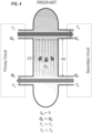
- a traditional hydraulic separator generally consists of a tubular metal casing or casing closed at the ends by two heads, said hydraulic separator internally defining a casing or chamber, advantageously oblong in shape, arranged in fluid connection with at least four through openings made on the outer casing. These openings respectively identify two delivery openings for the heat transfer fluid coming from the primary source circuit and entering the secondary user circuit, and two return openings for the heat transfer fluid returning to the primary source circuit and leaving the secondary user circuit.
- the hydraulic separator can be vertically arranged, with the oblong part perpendicular to the ground or horizontally arranged, with the oblong part parallel to the ground.
- These delivery and return openings are typically formed on the body of the hydraulic separator in fluid communication with the inner chamber and they are traditionally arranged perpendicular to the longitudinal axis of the hydraulic separator itself. In a normal installation configuration, with reference again to figure 4 , these delivery openings connect the hydraulic separator chamber with the delivery manifold arriving from the primary circuit and the delivery manifold entering the secondary user circuit, these delivery openings being generally facing each other and coaxially arranged in fluid communication on the internal chamber of the hydraulic separator.
- the return openings connect the hydraulic separator chamber with the return manifold arriving from the secondary circuit and the return manifold entering the primary source circuit, known as delivery openings since they are also generally facing each other and coaxially arranged in fluid communication on the internal chamber of the hydraulic separator.
- Hydraulic separators can be equipped with perforated baffles or nets, arranged inside the separator chamber and suitable to intercept the fluid flow passing from one opening to the other in such a way as to block any air or gas bubbles, impurities or slag, which are subsequently eliminated by waste valves usually placed on the heads of the outer casing of said hydraulic separator.
- the hydraulic separators can also be provided with an additional casing or insulating material coat to limit heat transmission and dispersion through the outer casing of the hydraulic separator.
- the incoming supply opening from the primary liquid circuit and the exhaust port leading to the secondary liquid circuit are substantially at a first height zone of the hydraulic separator.
- the exhaust port leading to the primary liquid circuit and the inlet opening from the secondary liquid circuit are substantially at a different height in a second height zone of the hydraulic separator.
- a set of open filling bodies are arranged with a large surface area in relation to the volume they occupy inside the separator.
- a hydraulic separator As previously mentioned, the function of a hydraulic separator is to separate the thermal circuit of a heating and/or cooling system into two hydraulic sub-circuits, a primary circuit and a secondary circuit, in such a way as to allow the incoming fluid from the delivery opening, coming from the heat source of the primary circuit, to be conveyed directly into the return manifold of the primary circuit, through the separator chamber, in case the circulation hydraulic pumps and the flow of the secondary user circuit are stopped while the fluid circulation pumps and the flow of the primary circuit are moving.
- a further drawback of traditional hydraulic separators is due to the fact that the thermal contamination between the two fluid streams at different temperatures, at the inlet and outlet port of the hydraulic separator, is even greater in the case of flatwise position installation of the device, position in which the elongated part of the separator body is arranged horizontally; in this case in fact, a less stratification of fluid at different temperatures occurs at the two ends of the hydraulic separator chamber with consequent greater arising of rotary eddy currents and convective flow inside the separator that increase the mixing between fluids at different temperatures, contributing to the increase in heat dispersion.
- a further object of the present invention is to provide to the user an hydraulic separator with reduces heat dispersion and a control method with a limited eddy currents circulation of fluid inside the chamber and with a less mixing of fluids at different temperatures.
- a further object of the present invention is to provide a reduced heat dispersion hydraulic separator capable to assure a high level of strength and reliability over time, such as to be further easily and economically manufactured.
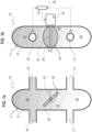
- hydraulic separator 10 with reduced heat dispersion, in figures specified with 10, for installation on hydronic systems for heating and/or cooling, said hydraulic separator 10 including:
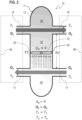
- the hydraulic separator 10 of the present invention has the innovative feature of comprising at least one mobile element 20 suitable for separating the chamber 14 of the body 11 in a first portion 14" of volume and a second portion 14" of volume, in such a way as to reduce up to closing the opening section of passage and of fluid contact between said first portion 14' and said second portion 14".
- said mobile element 20 can be advantageously realized as a throttle body comprising a butterfly valve 20' rotatably arranged inside chamber 14 by means of a rotation pin 22.
- said butterfly valve 20' is configured to rotate integrally with the rotation pin 22 rotatably housed by traditional rotation supports or bushes (not shown) disposed on the body 11 of the hydraulic separator 10.
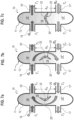
- said mobile element 20 may also comprise two or more mobile or rotating parts rotatably hinged in cooperation with respect to body 11 by means of respective rotation pins, said parts being suitable to prevent or allow the passage of fluid between said first portion 14' and said second portion 14" and vice versa.
- the mobile element 20 can generally comprise any traditional shutter or gate valve type or control system, said mobile element 20 being configured to open as result of a fluid pressure difference between said first 14" portion and the second 14" portion of chamber 14 or as consequence of mechanical actuation by a rotational or linear actuator 30, so as to allow the passage of fluid between said first 14" portion and said second 14" portion and vice versa.
- said mobile element 20 comprising the butterfly valve 20 can be advantageously connected by means of the rotation pin 22 to a rotational actuator 30, electromechanical, electric or fluidic servomechanism, said rotational actuator 30 being configured to rotate the rotation pin 22 with the butterfly valve 20' so as to limit or interrupt the fluid flow between the first 14' portion and the second 14" portion of chamber 14 and vice versa.
- Another innovative feature of the mobile element 20, comprising for example a 20" butterfly valve, is to can be made of insulating material with low thermal conductivity, such as polymeric plastics or thermo-polymers or other equivalent materials, in such a way as to further reduce the thermal gradient ⁇ T between said first portion 14' and said second portion 14" and limit or prevent the dispersion of heat Q D through the cross section of chamber 14 of hydraulic separator 10.
- insulating material with low thermal conductivity such as polymeric plastics or thermo-polymers or other equivalent materials
- the mobile element 20 includes a rotary shutter 20" hinged or clapet type having a discoidal shape conjugated with chamber 14, said rotary shutter 20" being hinged by means of the rotation pin 22 in correspondence of the diametrical edge with the internal wall of the same chamber 14.
- the measuring step of the physical variables of the fluid can comprise measurements of the pressure differential ⁇ p 1 of the fluid in the primary circuit 90 and the pressure differential ⁇ p 2 of the secondary circuit 90', measured by pressure sensors 40 between the inlet and outlet openings of the hydraulic separator 10 of the respective primary and secondary circuits 90, 90'.
Landscapes
- Engineering & Computer Science (AREA)
- Physics & Mathematics (AREA)
- Thermal Sciences (AREA)
- Chemical & Material Sciences (AREA)
- Combustion & Propulsion (AREA)
- Mechanical Engineering (AREA)
- General Engineering & Computer Science (AREA)
- General Physics & Mathematics (AREA)
- Automation & Control Theory (AREA)
- Fluid-Pressure Circuits (AREA)
- Lubricants (AREA)
- Thermotherapy And Cooling Therapy Devices (AREA)
Claims (17)
- Séparateur hydraulique (10) pour systèmes hydroniques de chauffage et/ou de refroidissement, comprenant :- un corps creux (11) avec un caisson (12), définissant intérieurement une chambre (14) ;- au moins deux premières ouvertures traversantes (16, 16') pour la distribution d'un fluide, et au moins deux secondes ouvertures traversantes (17, 17') pour le retour du fluide, lesdites premières ouvertures (16, 16') et lesdites secondes ouvertures (17, 17') étant pratiquées sur ledit caisson (12) du corps (11) et étant aptes à mettre en communication fluidique ladite chambre (14) avec des circuits externes par des moyens de raccordement hydrauliques ;- au moins un élément mobile (20) apte à séparer ladite chambre (14) du corps (11) en une première partie (14') et une seconde partie (14"), de manière à réduire la section d'ouverture de passage et de contact de fluide entre ladite première partie (14') et ladite seconde partie (14") ;caractérisé en ce que ledit au moins un élément mobile (20) est constitué d'un matériau isolant thermique ayant une faible conductivité thermique, de manière à limiter la conduction de chaleur thermique entre la première et la seconde partie (14', 14") de la chambre (14).
- Séparateur hydraulique (10) selon la revendication 1, dans lequel ledit élément mobile (20) est une vanne papillon (20') agencée de manière rotative à l'intérieur de la chambre (14) au moyen d'une broche de rotation (22).
- Séparateur hydraulique (10) selon la revendication 2, dans lequel ladite vanne papillon (20') est conçue pour tourner intégralement avec la broche de rotation (22) logée de manière rotative par des douilles ou des supports de rotation traditionnels disposées sur le corps (11).
- Séparateur hydraulique (10) selon la revendication 1, dans lequel ledit élément mobile (20) peut comprendre deux ou plusieurs parties mobiles (20") ou têtes, articulées de manière rotative par rapport au corps (11) au moyen de broches de rotation (22) respectives.
- Séparateur hydraulique (10) selon la revendication 1, dans lequel ledit élément mobile (20) est maintenu dans une position stable au moyen d'éléments élastiques de rappel traditionnels, tels que des ressorts de compression ou des ressorts de torsion.
- Séparateur hydraulique (10) selon la revendication 1, dans lequel ledit élément mobile (20) comprend une membrane déformable (70), avec une ouverture (72) normalement fermée.
- Séparateur hydraulique (10) selon la revendication 2, dans lequel ledit élément mobile (20) est actionné au moyen d'un actionneur linéaire ou rotatif (30), tel qu'un actionneur électromécanique, électrique ou fluidique, ledit actionneur (30) étant connecté à ladite unité de commande (60) et commandé au moyen de celle-ci.
- Séparateur hydraulique (10) selon la revendication 1, dans lequel ledit élément mobile (20) est constitué de plastiques polymères ou de matériaux thermopolymères ou d'autres matériaux équivalents.
- Séparateur hydraulique (10) selon la revendication 1, comprenant une pluralité de capteurs (40) ou transducteurs électriques ou électroniques, disposés au niveau desdites premières ouvertures (16, 16') ou desdites secondes ouvertures (17, 17'), lesdits capteurs (40) étant connectés à une unité de commande (60) et lesdits capteurs (40) étant configurés pour mesurer un paramètre physique du fluide.
- Séparateur hydraulique (10) selon la revendication 9, dans lequel lesdits capteurs (40) sont des capteurs de pression.
- Séparateur hydraulique (10) selon la revendication 9, dans lequel lesdits capteurs (40) sont des capteurs de température.
- Séparateur hydraulique (10) selon la revendication 9, dans lequel lesdits capteurs (40) sont des débitmètres massiques ou volumétriques.
- Séparateur hydraulique (10) selon la revendication 9, dans lequel une mesure effectuée par lesdits capteurs (40) correspond à un signal traité par l'unité de commande (60) et permettant de commander l'ouverture dudit élément mobile (20).
- Procédé de commande (100) pour des installations hydroniques de chauffage et/ou de refroidissement, comprenant les étapes consistant à :- fournir un séparateur hydraulique (10) selon la revendication 1 comprenant un corps creux (11) avec un caisson (12), l'intérieur de celui-ci définissant une chambre (14) ;- alimenter une distribution de fluide à travers au moins deux premières ouvertures (16, 16') du corps (11) et retourner le fluide à travers au moins deux secondes ouvertures (17, 17') du corps (11), lesdites premières ouvertures (16, 16') et lesdites secondes ouvertures (17, 17') étant conçues pour mettre en communication fluidique une chambre (14) du corps (11) avec un ou plusieurs circuits externes au moyen de raccordements hydrauliques ;- séparer ladite chambre interne (14) en une première partie (14') et en une seconde partie (14"), au moyen d'au moins un élément mobile thermiquement isolant (20),- commander, au moyen dudit élément mobile (20) l'ouverture de passage et la section de contact thermique selon une fonction de l'écoulement d'un fluide entre ladite première partie (14') et ladite seconde partie (14") de manière à limiter la conduction de chaleur thermique entre les mêmes première et seconde parties (14', 14") de la chambre (14).
- Procédé (100) selon la revendication 14, dans lequel l'étape de commande comprend en outre les étapes consistant à :- mesurer (102, 104) des variables physiques du fluide s'écoulant à travers les premières ouvertures (16, 16') et les secondes ouvertures (17, 17') du corps (11) par rapport au fluide du circuit primaire (90) au moyen de capteurs (40) ;- envoyer les données des variables détectées par les capteurs (40) et traiter au moyen d'une unité de commande (60) ;- commander l'élément mobile (20) au moyen d'un actionneur (30) selon une fonction de l'état des variables physiques de manière à faire varier la section de passage du fluide dans la chambre intérieure de fluide (14).
- Procédé (100) selon la revendication 14, dans lequel les étapes de mesure (102, 104) sont une étape de mesure du différentiel de pression du fluide dans le circuit primaire (90) et une étape de mesure de la différence de pression dans le circuit secondaire (90'), mesurés par les capteurs de pression (40) entre les ouvertures d'entrée et de sortie du séparateur hydraulique (10) des circuits primaire et secondaire (90, 90') respectifs.
- Procédé (100) selon la revendication 14, dans lequel les étapes de mesure (102, 104) sont une étape de mesure du différentiel de température du fluide dans le circuit primaire (90), et une étape de mesure du différentiel de température du fluide dans le circuit secondaire (90') mesurés par les capteurs de température (40) entre les ouvertures d'entrée et de sortie du séparateur hydraulique (10) des circuits primaire et secondaire (90, 90') respectifs.
Applications Claiming Priority (2)
| Application Number | Priority Date | Filing Date | Title |
|---|---|---|---|
| IT102019000007359A IT201900007359A1 (it) | 2019-05-27 | 2019-05-27 | Separatore idraulico a dispersione termica limitata e metodo di regolazione. |
| PCT/IB2020/054874 WO2020240370A1 (fr) | 2019-05-27 | 2020-05-22 | Séparateur hydraulique à dispersion de chaleur réduite et son procédé de commande |
Publications (3)
| Publication Number | Publication Date |
|---|---|
| EP3977018A1 EP3977018A1 (fr) | 2022-04-06 |
| EP3977018C0 EP3977018C0 (fr) | 2024-07-03 |
| EP3977018B1 true EP3977018B1 (fr) | 2024-07-03 |
Family
ID=67957317
Family Applications (1)
| Application Number | Title | Priority Date | Filing Date |
|---|---|---|---|
| EP20742868.1A Active EP3977018B1 (fr) | 2019-05-27 | 2020-05-22 | Séparateur hydraulique avec dispersion thermique réduite et procédé de commande à cet effet |
Country Status (7)
| Country | Link |
|---|---|
| US (1) | US12130026B2 (fr) |
| EP (1) | EP3977018B1 (fr) |
| ES (1) | ES2986185T3 (fr) |
| HU (1) | HUE067233T2 (fr) |
| IT (1) | IT201900007359A1 (fr) |
| PL (1) | PL3977018T3 (fr) |
| WO (1) | WO2020240370A1 (fr) |
Families Citing this family (2)
| Publication number | Priority date | Publication date | Assignee | Title |
|---|---|---|---|---|
| US11707705B2 (en) * | 2021-05-05 | 2023-07-25 | Nibco Inc. | Multi-function hydraulic separator |
| EP4617570A1 (fr) | 2024-03-11 | 2025-09-17 | Cordivari S.r.l. | Separateur hydraulique |
Family Cites Families (18)
| Publication number | Priority date | Publication date | Assignee | Title |
|---|---|---|---|---|
| US3150827A (en) * | 1961-10-24 | 1964-09-29 | York Shipley Inc | Apparatus for use in hot water heating systems |
| US3729051A (en) * | 1971-08-17 | 1973-04-24 | G Mannion | Process fluid flow regulation systems |
| FR2211108A5 (fr) * | 1972-12-20 | 1974-07-12 | Pont A Mousson | |
| US4516597A (en) * | 1983-04-01 | 1985-05-14 | Asahi Yukizai Kogyo Co., Ltd. | Anticorrosive butterfly valve |
| US4566628A (en) * | 1984-03-02 | 1986-01-28 | Tekmar Angewandte Elektronik Gmbh & Co. Kg | Method of and system for controlling the ratio between the water flow rate in the primary circuit and the water flow rate in the secondary circuit of a hot water heating system |
| DE3568859D1 (en) * | 1984-12-24 | 1989-04-20 | Tno | Apparatus and method for adjusting a central heating installation |
| US5139225A (en) * | 1990-11-05 | 1992-08-18 | Micron Technology, Inc. | Pneumatically controlled multiple valve system for fluid transfer |
| FR2740204B1 (fr) * | 1995-10-18 | 1997-12-26 | Guillot Ind Sa | Dispositif de raccordement sur une chaudiere regulee permettant l'alimentation et la regulation de deux circuits de chauffage |
| DE29911410U1 (de) * | 1998-07-02 | 1999-08-12 | Joh. Vaillant Gmbh U. Co, 42859 Remscheid | Heizungsanlage |
| DE10102022B4 (de) * | 2000-01-15 | 2010-07-29 | Joh. Vaillant Gmbh | Wasserheizanlage |
| US6223772B1 (en) * | 2000-02-15 | 2001-05-01 | Delphi Technologies, Inc. | Dual function valve assembly |
| JP2006070946A (ja) * | 2004-08-31 | 2006-03-16 | Asahi Organic Chem Ind Co Ltd | 調節弁 |
| US7117888B2 (en) | 2005-11-02 | 2006-10-10 | Flamco B.V. | Hydraulic separator |
| FR2894013A1 (fr) * | 2005-11-25 | 2007-06-01 | Amblard Sa Ets | Repartiteur hydraulique de raccordement de deux generateurs de chaleur |
| US7954508B2 (en) * | 2006-03-03 | 2011-06-07 | KBK Technologies, Inc. | Electronically controlled valve actuator in a plumbed water line within a water conditioning management system |
| DE202006019415U1 (de) * | 2006-12-22 | 2007-04-05 | Watts Industries Deutschland Gmbh | Vorrichtung zum Speisen von Hoch- und Niedertemperaturverbrauchskreisen |
| US9864383B2 (en) * | 2015-04-02 | 2018-01-09 | Belimo Holding Ag | Method and system for determining characteristic parameters of a hydraulic network |
| PL3184917T3 (pl) * | 2015-12-24 | 2021-07-19 | Delta Systemtechnik Gmbh | Urządzenie regulujące ilość strumienia przepływu, element sprzęgający oraz instalacja do podgrzewania wody przemysłowej |
-
2019
- 2019-05-27 IT IT102019000007359A patent/IT201900007359A1/it unknown
-
2020
- 2020-05-22 EP EP20742868.1A patent/EP3977018B1/fr active Active
- 2020-05-22 HU HUE20742868A patent/HUE067233T2/hu unknown
- 2020-05-22 PL PL20742868.1T patent/PL3977018T3/pl unknown
- 2020-05-22 ES ES20742868T patent/ES2986185T3/es active Active
- 2020-05-22 US US17/613,734 patent/US12130026B2/en active Active
- 2020-05-22 WO PCT/IB2020/054874 patent/WO2020240370A1/fr not_active Ceased
Also Published As
| Publication number | Publication date |
|---|---|
| US12130026B2 (en) | 2024-10-29 |
| IT201900007359A1 (it) | 2020-11-27 |
| EP3977018C0 (fr) | 2024-07-03 |
| EP3977018A1 (fr) | 2022-04-06 |
| HUE067233T2 (hu) | 2024-10-28 |
| US20220243929A1 (en) | 2022-08-04 |
| PL3977018T3 (pl) | 2024-08-19 |
| WO2020240370A1 (fr) | 2020-12-03 |
| ES2986185T3 (es) | 2024-11-08 |
Similar Documents
| Publication | Publication Date | Title |
|---|---|---|
| CN101990655B (zh) | 集成式过压监控装置 | |
| EP3977018B1 (fr) | Séparateur hydraulique avec dispersion thermique réduite et procédé de commande à cet effet | |
| US10619757B2 (en) | Valve and a method of controlling a valve in a fluid conduit | |
| CA2666933C (fr) | Module integre de pompage de refrigerant | |
| CN104040261B (zh) | 供热装置 | |
| US20180094807A1 (en) | Measuring Turbulent Flows | |
| CN103174868A (zh) | 压力和流量范围可调的隔膜阀 | |
| EP1024332A2 (fr) | Vanne à servocommande pour systèmes de conditionnement d'air appelés à quattre conduits | |
| KR900702442A (ko) | 온도 자동 압력 균형 밸브조립체 | |
| CN109236614A (zh) | 一种活塞式压缩机控制气缸冷却水流量的温控阀 | |
| AU690536B2 (en) | Automatic recirculation valve | |
| EP1585919B1 (fr) | Purgeur de condensats | |
| NO309997B1 (no) | Automatisk resirkuleringsventil | |
| JP7835862B2 (ja) | 圧力制御を改善した流体レギュレータ | |
| CN219549749U (zh) | 单向阀、热力平衡阀及供水系统 | |
| CN201517442U (zh) | 一种油温调节器 | |
| CN205605912U (zh) | 压差平衡阀 | |
| EP2568794A2 (fr) | Système de commande pour commander une performance de refroidissement | |
| EP4180667A1 (fr) | Dispositif de chauffage et/ou de refroidissement doté d'une pompe intégrée à un échangeur de chaleur | |
| IT202200021621A1 (it) | Sistema e relativo metodo di taratura della pressione di bilanciamento di un impianto termoidraulico | |
| CN116265852A (zh) | 多段式热交换器 | |
| EP2568224B1 (fr) | Soupape d'arrêt | |
| SE448395B (sv) | Hevarmsfri tryckgivare |
Legal Events
| Date | Code | Title | Description |
|---|---|---|---|
| STAA | Information on the status of an ep patent application or granted ep patent |
Free format text: STATUS: UNKNOWN |
|
| STAA | Information on the status of an ep patent application or granted ep patent |
Free format text: STATUS: THE INTERNATIONAL PUBLICATION HAS BEEN MADE |
|
| PUAI | Public reference made under article 153(3) epc to a published international application that has entered the european phase |
Free format text: ORIGINAL CODE: 0009012 |
|
| STAA | Information on the status of an ep patent application or granted ep patent |
Free format text: STATUS: REQUEST FOR EXAMINATION WAS MADE |
|
| 17P | Request for examination filed |
Effective date: 20211119 |
|
| AK | Designated contracting states |
Kind code of ref document: A1 Designated state(s): AL AT BE BG CH CY CZ DE DK EE ES FI FR GB GR HR HU IE IS IT LI LT LU LV MC MK MT NL NO PL PT RO RS SE SI SK SM TR |
|
| DAV | Request for validation of the european patent (deleted) | ||
| DAX | Request for extension of the european patent (deleted) | ||
| GRAP | Despatch of communication of intention to grant a patent |
Free format text: ORIGINAL CODE: EPIDOSNIGR1 |
|
| STAA | Information on the status of an ep patent application or granted ep patent |
Free format text: STATUS: GRANT OF PATENT IS INTENDED |
|
| INTG | Intention to grant announced |
Effective date: 20240320 |
|
| GRAS | Grant fee paid |
Free format text: ORIGINAL CODE: EPIDOSNIGR3 |
|
| GRAA | (expected) grant |
Free format text: ORIGINAL CODE: 0009210 |
|
| STAA | Information on the status of an ep patent application or granted ep patent |
Free format text: STATUS: THE PATENT HAS BEEN GRANTED |
|
| AK | Designated contracting states |
Kind code of ref document: B1 Designated state(s): AL AT BE BG CH CY CZ DE DK EE ES FI FR GB GR HR HU IE IS IT LI LT LU LV MC MK MT NL NO PL PT RO RS SE SI SK SM TR |
|
| REG | Reference to a national code |
Ref country code: CH Ref legal event code: EP |
|
| REG | Reference to a national code |
Ref country code: DE Ref legal event code: R096 Ref document number: 602020033350 Country of ref document: DE |
|
| U01 | Request for unitary effect filed |
Effective date: 20240719 |
|
| REG | Reference to a national code |
Ref country code: GR Ref legal event code: EP Ref document number: 20240401681 Country of ref document: GR Effective date: 20240819 |
|
| U07 | Unitary effect registered |
Designated state(s): AT BE BG DE DK EE FI FR IT LT LU LV MT NL PT SE SI Effective date: 20240801 |
|
| REG | Reference to a national code |
Ref country code: SK Ref legal event code: T3 Ref document number: E 44557 Country of ref document: SK |
|
| REG | Reference to a national code |
Ref country code: HU Ref legal event code: AG4A Ref document number: E067233 Country of ref document: HU |
|
| REG | Reference to a national code |
Ref country code: ES Ref legal event code: FG2A Ref document number: 2986185 Country of ref document: ES Kind code of ref document: T3 Effective date: 20241108 |
|
| PG25 | Lapsed in a contracting state [announced via postgrant information from national office to epo] |
Ref country code: NO Free format text: LAPSE BECAUSE OF FAILURE TO SUBMIT A TRANSLATION OF THE DESCRIPTION OR TO PAY THE FEE WITHIN THE PRESCRIBED TIME-LIMIT Effective date: 20241003 |
|
| PG25 | Lapsed in a contracting state [announced via postgrant information from national office to epo] |
Ref country code: IS Free format text: LAPSE BECAUSE OF FAILURE TO SUBMIT A TRANSLATION OF THE DESCRIPTION OR TO PAY THE FEE WITHIN THE PRESCRIBED TIME-LIMIT Effective date: 20241103 |
|
| PG25 | Lapsed in a contracting state [announced via postgrant information from national office to epo] |
Ref country code: HR Free format text: LAPSE BECAUSE OF FAILURE TO SUBMIT A TRANSLATION OF THE DESCRIPTION OR TO PAY THE FEE WITHIN THE PRESCRIBED TIME-LIMIT Effective date: 20240703 |
|
| PG25 | Lapsed in a contracting state [announced via postgrant information from national office to epo] |
Ref country code: RS Free format text: LAPSE BECAUSE OF FAILURE TO SUBMIT A TRANSLATION OF THE DESCRIPTION OR TO PAY THE FEE WITHIN THE PRESCRIBED TIME-LIMIT Effective date: 20241003 |
|
| PG25 | Lapsed in a contracting state [announced via postgrant information from national office to epo] |
Ref country code: RS Free format text: LAPSE BECAUSE OF FAILURE TO SUBMIT A TRANSLATION OF THE DESCRIPTION OR TO PAY THE FEE WITHIN THE PRESCRIBED TIME-LIMIT Effective date: 20241003 Ref country code: NO Free format text: LAPSE BECAUSE OF FAILURE TO SUBMIT A TRANSLATION OF THE DESCRIPTION OR TO PAY THE FEE WITHIN THE PRESCRIBED TIME-LIMIT Effective date: 20241003 Ref country code: IS Free format text: LAPSE BECAUSE OF FAILURE TO SUBMIT A TRANSLATION OF THE DESCRIPTION OR TO PAY THE FEE WITHIN THE PRESCRIBED TIME-LIMIT Effective date: 20241103 Ref country code: HR Free format text: LAPSE BECAUSE OF FAILURE TO SUBMIT A TRANSLATION OF THE DESCRIPTION OR TO PAY THE FEE WITHIN THE PRESCRIBED TIME-LIMIT Effective date: 20240703 |
|
| PG25 | Lapsed in a contracting state [announced via postgrant information from national office to epo] |
Ref country code: SM Free format text: LAPSE BECAUSE OF FAILURE TO SUBMIT A TRANSLATION OF THE DESCRIPTION OR TO PAY THE FEE WITHIN THE PRESCRIBED TIME-LIMIT Effective date: 20240703 |
|
| PLBE | No opposition filed within time limit |
Free format text: ORIGINAL CODE: 0009261 |
|
| STAA | Information on the status of an ep patent application or granted ep patent |
Free format text: STATUS: NO OPPOSITION FILED WITHIN TIME LIMIT |
|
| 26N | No opposition filed |
Effective date: 20250404 |
|
| U20 | Renewal fee for the european patent with unitary effect paid |
Year of fee payment: 6 Effective date: 20250520 |
|
| PGFP | Annual fee paid to national office [announced via postgrant information from national office to epo] |
Ref country code: PL Payment date: 20250426 Year of fee payment: 6 |
|
| PGFP | Annual fee paid to national office [announced via postgrant information from national office to epo] |
Ref country code: ES Payment date: 20250602 Year of fee payment: 6 |
|
| PGFP | Annual fee paid to national office [announced via postgrant information from national office to epo] |
Ref country code: HU Payment date: 20250430 Year of fee payment: 6 |
|
| PGFP | Annual fee paid to national office [announced via postgrant information from national office to epo] |
Ref country code: GR Payment date: 20250523 Year of fee payment: 6 |
|
| PGFP | Annual fee paid to national office [announced via postgrant information from national office to epo] |
Ref country code: RO Payment date: 20250430 Year of fee payment: 6 |
|
| PGFP | Annual fee paid to national office [announced via postgrant information from national office to epo] |
Ref country code: SK Payment date: 20250425 Year of fee payment: 6 |
|
| PGFP | Annual fee paid to national office [announced via postgrant information from national office to epo] |
Ref country code: CZ Payment date: 20250428 Year of fee payment: 6 |
|
| REG | Reference to a national code |
Ref country code: CH Ref legal event code: H13 Free format text: ST27 STATUS EVENT CODE: U-0-0-H10-H13 (AS PROVIDED BY THE NATIONAL OFFICE) Effective date: 20251223 |
|
| PG25 | Lapsed in a contracting state [announced via postgrant information from national office to epo] |
Ref country code: CH Free format text: LAPSE BECAUSE OF NON-PAYMENT OF DUE FEES Effective date: 20250531 |
|
| GBPC | Gb: european patent ceased through non-payment of renewal fee |
Effective date: 20250522 |
|
| PG25 | Lapsed in a contracting state [announced via postgrant information from national office to epo] |
Ref country code: MC Free format text: LAPSE BECAUSE OF FAILURE TO SUBMIT A TRANSLATION OF THE DESCRIPTION OR TO PAY THE FEE WITHIN THE PRESCRIBED TIME-LIMIT Effective date: 20240703 |
|
| PG25 | Lapsed in a contracting state [announced via postgrant information from national office to epo] |
Ref country code: GB Free format text: LAPSE BECAUSE OF NON-PAYMENT OF DUE FEES Effective date: 20250522 |
|
| PG25 | Lapsed in a contracting state [announced via postgrant information from national office to epo] |
Ref country code: IE Free format text: LAPSE BECAUSE OF NON-PAYMENT OF DUE FEES Effective date: 20250522 |