EP3978094A1 - Flüssig-flüssig-extraktor und batterie, die solche extraktoren umfasst - Google Patents
Flüssig-flüssig-extraktor und batterie, die solche extraktoren umfasst Download PDFInfo
- Publication number
- EP3978094A1 EP3978094A1 EP21306319.1A EP21306319A EP3978094A1 EP 3978094 A1 EP3978094 A1 EP 3978094A1 EP 21306319 A EP21306319 A EP 21306319A EP 3978094 A1 EP3978094 A1 EP 3978094A1
- Authority
- EP
- European Patent Office
- Prior art keywords
- liquid
- settling
- phases
- extractors
- cell
- Prior art date
- Legal status (The legal status is an assumption and is not a legal conclusion. Google has not performed a legal analysis and makes no representation as to the accuracy of the status listed.)
- Granted
Links
Images



Classifications
-
- B—PERFORMING OPERATIONS; TRANSPORTING
- B01—PHYSICAL OR CHEMICAL PROCESSES OR APPARATUS IN GENERAL
- B01D—SEPARATION
- B01D11/00—Solvent extraction
- B01D11/04—Solvent extraction of solutions which are liquid
- B01D11/0488—Flow sheets
-
- B—PERFORMING OPERATIONS; TRANSPORTING
- B01—PHYSICAL OR CHEMICAL PROCESSES OR APPARATUS IN GENERAL
- B01D—SEPARATION
- B01D11/00—Solvent extraction
- B01D11/04—Solvent extraction of solutions which are liquid
- B01D11/0492—Applications, solvents used
-
- B—PERFORMING OPERATIONS; TRANSPORTING
- B01—PHYSICAL OR CHEMICAL PROCESSES OR APPARATUS IN GENERAL
- B01D—SEPARATION
- B01D11/00—Solvent extraction
- B01D11/04—Solvent extraction of solutions which are liquid
- B01D11/0426—Counter-current multistage extraction towers in a vertical or sloping position
-
- B—PERFORMING OPERATIONS; TRANSPORTING
- B01—PHYSICAL OR CHEMICAL PROCESSES OR APPARATUS IN GENERAL
- B01D—SEPARATION
- B01D11/00—Solvent extraction
- B01D11/04—Solvent extraction of solutions which are liquid
- B01D11/0446—Juxtaposition of mixers-settlers
-
- B—PERFORMING OPERATIONS; TRANSPORTING
- B01—PHYSICAL OR CHEMICAL PROCESSES OR APPARATUS IN GENERAL
- B01D—SEPARATION
- B01D11/00—Solvent extraction
- B01D11/04—Solvent extraction of solutions which are liquid
- B01D11/0446—Juxtaposition of mixers-settlers
- B01D11/0453—Juxtaposition of mixers-settlers with narrow passages limited by plates, walls, e.g. helically coiled tubes
-
- B—PERFORMING OPERATIONS; TRANSPORTING
- B01—PHYSICAL OR CHEMICAL PROCESSES OR APPARATUS IN GENERAL
- B01D—SEPARATION
- B01D11/00—Solvent extraction
- B01D2011/002—Counter-current extraction
-
- Y—GENERAL TAGGING OF NEW TECHNOLOGICAL DEVELOPMENTS; GENERAL TAGGING OF CROSS-SECTIONAL TECHNOLOGIES SPANNING OVER SEVERAL SECTIONS OF THE IPC; TECHNICAL SUBJECTS COVERED BY FORMER USPC CROSS-REFERENCE ART COLLECTIONS [XRACs] AND DIGESTS
- Y02—TECHNOLOGIES OR APPLICATIONS FOR MITIGATION OR ADAPTATION AGAINST CLIMATE CHANGE
- Y02E—REDUCTION OF GREENHOUSE GAS [GHG] EMISSIONS, RELATED TO ENERGY GENERATION, TRANSMISSION OR DISTRIBUTION
- Y02E60/00—Enabling technologies; Technologies with a potential or indirect contribution to GHG emissions mitigation
- Y02E60/10—Energy storage using batteries
Definitions
- the invention lies in the field of chemical engineering and relates more particularly to liquid-liquid extractors, as well as to a battery comprising such extractors.
- Extractors are intended to carry out transfers of solutes between two immiscible phases, commonly called aqueous phases and organic phase or solvent, or heavy phase and light phase. They belong to the mixer-settler family.
- the two liquid phases are mixed by creating an emulsion, then separated by decantation, which allows the solute initially contained in one of the liquids to be transferred to the second.
- a battery of several stages is used, each comprising such an extractor, in order to obtain a better extraction in a process where the phases pass successively through each of them.
- Extractors generally include a mixing compartment in which the emulsion is formed by the movement of a mobile body, and a decanter compartment in which the liquid phases are separated. The circulation of the phases in these batteries is generally countercurrent.
- Liquid-liquid extractors of different sizes are offered, from large industrial devices capable of containing several tens of cubic meters per floor, to small volume devices, the extractors of which can each contain a few hundred milliliters per floor.
- Extractors with very small capacity and very low extraction rate have been designed for applications in the field of nuclear fuel. Very low flow rates can be from a few tens to a few hundred milliliters per hour.
- An example of such an extractor is described in the document EN 1580163 A .
- a battery of extractors adapted to such applications, and allowing it to be mounted and modified easily by remote manipulation, is described in the document FR 2831075 A .
- a problem specific to small flow rates is that the capillary forces can make the flows of the liquid phases irregular, with variations, which may be unacceptable, in the levels of the phases or their mixing in the compartments.
- Another frequent problem encountered is the difficulty in modifying a battery of extractors in a hostile environment, nuclear for example, or in dismantling and adjusting the individual extractors, which are often precisely small for low flow rates, by means of remote manipulation or through a glove box.
- the invention relates firstly to an improved liquid-liquid extractor, which can be very small in size, and provided with various improvements ensuring in particular a good regularity of flow, even at very low flow, facilitated settling and various equipment easy to install. on the fixed structure of the extractor by remote manipulation if necessary.
- Another aspect of the invention is a battery comprising such extractors and designed so as to be able to be used easily in a nuclear environment, that is to say in a glove box or in a shielded chain, thanks to great ease of assembly. and assembly by remote manipulation.
- the invention in a general form, relates to a liquid-liquid extractor comprising a hollow block of communicating mixing and settling cells, inlet ducts for two liquid phases leading to the mixing cell and ducts outlet of the two liquid phases connected to the settling cell, characterized in that the outlet ducts are provided with overflows adjacent to the settling cell, and each provided with an overflow edge of the liquid phases having an irregular height in the form of a broken line delimiting a plurality of reliefs.
- Overflows or weirs are obstacles to the flow of liquid phases, which define heights above which the flow begins.
- the overflows discussed here are placed at the outlets of the settling cell, at different heights, so as to adjust the height of each of the phases at this location.
- a broken line will here be called a line typically delimiting a plurality of alternately protruding and re-entrant reliefs having a slope whose evolution is irregular, with several reversals of direction, along the line.
- the flow remains through the bottoms of the re-entrant reliefs, thanks to their narrowness, in thus avoiding significant effects of capillary forces and liquid retention upstream of overflows.
- Such an effect does not exist on a rectilinear overflow, nor a horizontal or gently sloping flow surface, nor even at the bottom of a channel of circular section whose radius of curvature would be much greater than the reliefs envisaged here.
- the overflow edge of at least one of the overflows is formed by a plurality of indentations narrowing downwards to zero width and formed by two oblique edges.
- the overflow edge of at least one of the overflows is jagged, composed of identical and uniformly distributed alternating reliefs.
- one of the overflows is placed at a junction between the settling cell and the outlet duct of one of said liquid phases called light phase; it defines the total height of the phases in the settling cell.
- another of the overflows can be placed in an inlet well of the outlet conduit of another of the so-called heavy phase liquid phases, at an adjustable height in the well of input to adjust the relative residence time of the two liquid phases in the extractor.
- the outlet ducts mainly or essentially consist of channels open to an upper face of the block making up the structure of the extractor.
- the effect of this construction of the open outlet channels is however similar to that of the reliefs of the overflows: the effects of capillarity, the retention of flows at low flow rates and also the trapping of air bubbles are reduced, and a better regularity of the flow is therefore still obtained.
- These open channels which are the seat of gravity flows of the liquid phases, can advantageously extend in a straight line, for example parallel to the side faces of the block where the outlet ducts open; they can be quite long without inconvenience and extend for example over at least half of a length of the block, measured parallel to the side faces.
- the flows remain easy and regular, and the extractor block remains compact.
- This arrangement is useful for obtaining an extractor where the inlet and outlet openings for each of the liquid phases are aligned along two lines perpendicular to the side faces.
- the extractors then all have the same orientation, with their similar equipment aligned along parallel lines, which facilitates manipulations on the battery, improves its appearance and allows overall settling examinations, for all stages of the battery, at a glance, if the settling cells are all turned towards an observer and exposed to view, for example through a window or other transparent wall .
- the outlet channels are also advantageously quite wide, possibly each with a width equal to at least one third of a width, measured perpendicular to the side faces, of the settling cell, again in order to allow regularization of the gravity flow. at these places.
- the extractor may comprise a third overflow, arranged between the mixing cell and the settling cell, and equipped, in a manner analogous to the previous ones and with the same effect, with an overflow edge for the liquid phases having an irregular height. in the form of a broken line delimiting a plurality of reliefs.
- Another aspect of the invention is a liquid-liquid extraction battery comprising at least one extractor in accordance with the above; the extractor or extractors and end modules are aligned and clamped on a rail, the end modules comprising connections to countercurrent liquid phase circuits in the battery, the inlets and the outlets of each of the phases being in extension between the extractors.
- the battery can advantageously comprise spacer plates clamped against the extractors and bearing seals surrounding the inlet and outlet openings for the liquid phases, so as to further facilitate assembly of the device.
- the liquid-liquid extractors, the end modules, and possibly the spacer plates, can be nested on the rail by being able to slide along it, again in order to facilitate assembly.
- Another improvement that can be considered is to provide the battery with heating means. These means can be established inside the rail or under it, and consist of a heating layer, for example by electrical resistance.
- Another device may comprise a heat transfer fluid circulation device passing through the block of each of the battery extractors.
- the outlet ducts 12 and 13 of the heavy phase and of the light phase mainly comprise portions parallel to the side faces 2 and 3, respectively called heavy phase outlet channel 14 and light phase outlet channel 15;
- the heavy phase outlet channel 14 is adjacent to the first side face 2 and extends from an inlet well 16 to an outlet well 17, the first of which is adjacent to the settling cell 9 and to the front face 4, over a little more than half the length of the extractor between the front face 4 and the rear face 5.
- the light phase outlet channel 15 communicates with the settling cell 9 by a phase overflow light 18 and extends to an outlet well 19 being adjacent to the second side face 3 over approximately half of said length of the extractor 60.
- the front face 4 is partially transparent and provided with a porthole 20 (illustrated in figure 2 , 6 and 9 ) which makes it possible to observe, for each extractor 60 of a battery, the progress of the decantation and the evacuation of the phases: the window 20 in fact partially delimits the decantation cell 9 and the inlet of the outlet conduit light phase 13. Alternatively, the entire block 1 could be transparent.
- the heavy phase and light phase output channels 14 and 15 are equipped with intermediate wells 21 and 22 which can receive spectrophotometric probes for on-line analysis of the composition of the phases.
- the flow movement of the light phase is represented by the arrows 53.
- the figure 2 and 3 further illustrate the heavy phase outlet duct 12.
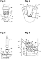
- the inlet well 16 has a lower opening 23 which communicates with the bottom of the settling cell 9: the heavy phase accumulates in the inlet well 16 during the process and eventually reaches a heavy phase overflow 24 which is a separate room, shown in detail at picture 3 .
- the heavy phase overflow 24 is generally cylindrical in shape and comprises, from top to bottom, a handle 25 for gripping, a thread 26 and a sleeve 27.
- the handle 25 projects from the extractor above the upper face 7, the thread 26 is engaged in an internal thread corresponding to the top of the inlet well 16, and the sleeve 27 extends into the latter with play, with the exception of its lower part, which is provided with a gasket O-ring seal 28 rubbing against inlet well 16 above lower opening 23 and below a connection to heavy phase outlet channel 14.
- An upper portion of the sleeve 27, above the seal 28, is provided with triangular cutouts 29 distributed over its periphery and delimited by a lower edge 30 sawtooth, so that the triangular cutouts 29 each have a lower point 31 forming an acute angle.
- the lower tips 31 extend in front of the connection to the heavy phase outlet channel 14, and the heavy phase flows into this channel, once it has reached the level of the triangular cutouts 29. It can then flow into the heavy phase outlet channel 14, before joining the outlet shaft 17 and leaving the extractor 60.
- the flow movement of the heavy phase is represented by the arrows 32.
- the construction of the extractor 60 from a unitary and hollowed block 1 makes it possible to add various equipment thereto by mounting them via the upper face 7, by screwing as with the heavy phase overflow 24, or by simply plugging in by translation vertical, like the equipment that will now be described.
- the adjustments and manipulations on the extractors 60, as well as their assemblies in batteries, are considerably facilitated and can be accomplished by remote manipulation devices or through glove boxes.
- the figure 4 represents a mixing chamber 33 which is pushed into the mixing cavity 8 with a narrow clearance. It is a hollow part, approximately cylindrical, open at the top and provided on one side with an upper notch 34 whose lower edge is a mixture overflow 35, with a lower opening 36 at the bottom, and with a vertical pin 37 standing vertically at its upper side.
- the upper notch 34 and the mixing overflow 35 extend in front of the upper part of the settling cell 9 and define the level above which the mixture present in the chamber 33 can flow into the settling cell 9.
- the mixture overflow 35 has a jagged or crenellated shape, its upper edge through which the mixture flows towards the settling cell being in the form of a broken line forming alternately small protruding and re-entrant reliefs.
- the height of this upper edge is therefore variable.
- the re-entrant reliefs advantageously narrow downwards, which is verified if the reliefs are separated by oblique faces. In the extreme, one can envisage that the oblique faces meet at a sharp angle, to give the bottom of the re-entrant reliefs a zero width.
- the open-air construction of the outlet channels 14 and 15 also has the same purpose of reducing the effect of capillary forces and regulating the flows.
- the figure 5 illustrates a bearing block 38 carrying a stirring wheel 39 with vertical blades, which can be placed on the upper edge 40 of the mixing chamber 33 at a fixed angular position, thanks to the vertical pin 37; and a motor 41 which can be placed on the upper edge of the bearing block 38, so as to cause the stirring wheel 39 to rotate, when it is started, the stirring wheel 39 entering the mixing chamber 33 at this time to mix the liquid phases and create an emulsion.
- the first is engaged in the settling cell 9, bears the general reference 42 ( figure 6 ) and may comprise a knockdown plate 43, as well as two coalescing grids 44 and 45, all connected to an upper plate 46.
- the knockdown plate 43 is vertical and adjacent to the mixing cell 8 ; its function is to force the mixture to enter the settling cell 9 through the middle.
- the coalescence grids 44 and 45 are, as their name indicates, intended to promote the coalescence of that of the phases which is in emulsion in the other, thus giving a heavy phase and a light phase clearly separated and superimposed in the settling cell 9.
- One of the coalescence grids 44 can be hydrophobic and the other hydrophilic, so as to promote both the coalescence of the organic phase (generally the light phase) and that of the aqueous phase (generally the heavy phase) depending on the category of the emulsion.
- two similar coalescence grids could be used, for emulsion phases which are difficult to reconstitute.
- the coalescence grids 44 and 45 are also vertical, parallel to the drawdown plate 43 and extend towards the middle of the settling cell 9 in any order.
- a pull tab 47 rising upwards and attached to the top plate 46 is added to allow manipulation of the equipment.
- FIG 7 Another removable piece of equipment is shown in figure 7 and consists of a recycling pump 48 useful in certain processes and which serves to produce a partial return of one of the phases, here the heavy phase, to the mixing cell 8.
- the recycling pump 48 is placed on a console 49 horizontal fixed to the rear face 5 of the block 1 and protruding towards the rear (for the sake of clarity, however, the recycling pump 48 has been shown here raised above the bracket 49). It is provided with a vertical suction tube 50 and a discharge tube 51, capable of penetrating respectively into the outlet well 17 of the heavy phase to suck up a flow therefrom and into a vertical recycling well 52 dug in block 1 near the mixing cell 8.
- the recycling well 52 like the inlet conduits 10 and 11 for the heavy phase and the light phase, open into the mixing cell 8 and the liquids passing through them then enter the mixing chamber 34 through the lower opening 36.
- the figure 8 shows that the light phase outlet channel 15 is uneven with respect to the light phase overflow 18.
- the light phase overflow is here again materialized by an overflow edge crossed by the flow of the liquid and formed by a line broken, forming here background horizontal parts and oblique parts, and thus flat-topped protruding reliefs alternating with triangular indentations narrowing downwards.
- Such a battery is shown in figure 9 .
- the extractors 60 are arranged side by side on a flat support rail 61 whose ends are placed on supports 62. It will be noted that the portholes 20 are aligned on the same face of the battery, in order to provide rapid overall examinations processes carried out in the battery.
- This arrangement is indebted in particular to the arrangement of the mixing cells 8 aligned with each other and the settling cells 9 aligned with each other parallel to the support rail, and to the heavy phase 14 and light phase 15 channels that are quite long and parallel to the faces sides 2 and 3 by which the extractors 60 are assembled, so that the inlet and outlet ducts of each of the phases come out of the block 1 at positions aligned in the direction perpendicular to the side faces 2 and 3 and parallel to the rail of carrier 61; whereas a conventional arrangement of battery extractors is head to tail, with mixing and settling cells alternating along two parallel lines, which allows for shorter liquid phase outlet ducts almost perpendicular to the faces lateral (as are still here the inlet ducts 10 and 11), but therefore with the disadvantage that the overall examination of the settling of the floors is no longer possible.
- the support rail 61 can consist of any number of individual plates 63 assembled to each other by screws and shaped fittings at their junction 64.
- the ends of the support rail carry abutments 65 and 66 opposed, of which at least one (66) may include a capstan for tightening the battery, preventing the disjunctions of its elements and ensuring sealing channels 10 to 13.
- the battery comprises, at its ends and therefore in contact with the stops 65 and 66, two end modules 67 and 68, also parallelepipedic and comprising fittings, generally referenced by 69, of input and output phases leading to the rest of their circulation circuits.
- the end modules 67 and 68 communicate with the inlet and outlet ducts of the adjacent extractor 60.
- the cohesion of the battery is further ensured by portions of slideways and lugs 70 (shown in picture 2 ) allowing the extractors 60 to slide on the support rail 61, but without being able to lift them.
- a similar system is provided on the end modules 67 and 68.
- the battery is completed by ( figure 11 ) spacer plates 71 between the extractors 60, which are provided with two bores 72 and 73 carrying seals 74 and 75.
- the spacer plates 71 are provided with a lower groove 76 which fits on the support rail 61 and keeps them in position on it.
- FIG. 12 may include, in a block 77 a little larger than the block 1 described so far, heat transfer conduits comprising an inlet conduit 78 for heat transfer fluid located near the rear face 5, an outlet conduit 79 for the fluid heat carrier also located near the rear face 5, and, connecting the inlet and outlet ducts 78 and 79, an interior duct comprising successively a first descending portion 80, a longitudinal portion 81 close to the lower face 6 and directed towards the front face 4, a second longitudinal portion 82 which brings the fluid back to the rear face 5, parallel and in the opposite direction to the first longitudinal portion 81, and an ascending portion 83.
- the longitudinal portions 81 and 82 are separated by a partition 84. They pass the heat transfer fluid below the mixing 8 and settling 9 cells.
- each plate 63 of the support rail 61 which is provided with a hollow 85, opening for example at its lower face, and which is occupied by a flat electric heating sheet 86 , fed by fittings to the outside 87.
- a cover 88 is screwed on to close the recess 85 and hold the heating mat 86 there.
Landscapes
- Chemical & Material Sciences (AREA)
- Chemical Kinetics & Catalysis (AREA)
- Extraction Or Liquid Replacement (AREA)
- Engineering & Computer Science (AREA)
- Manufacturing & Machinery (AREA)
- Electrochemistry (AREA)
- General Chemical & Material Sciences (AREA)
- Inorganic Chemistry (AREA)
- Filling, Topping-Up Batteries (AREA)
- Fuel Cell (AREA)
- Hybrid Cells (AREA)
Applications Claiming Priority (1)
| Application Number | Priority Date | Filing Date | Title |
|---|---|---|---|
| FR2010084A FR3114755B1 (fr) | 2020-10-02 | 2020-10-02 | Extracteur liquide-liquide et batterie comprenant de tels extracteurs |
Publications (2)
| Publication Number | Publication Date |
|---|---|
| EP3978094A1 true EP3978094A1 (de) | 2022-04-06 |
| EP3978094B1 EP3978094B1 (de) | 2023-05-03 |
Family
ID=74758878
Family Applications (1)
| Application Number | Title | Priority Date | Filing Date |
|---|---|---|---|
| EP21306319.1A Active EP3978094B1 (de) | 2020-10-02 | 2021-09-24 | Flüssig-flüssig-extraktor und batterie, die solche extraktoren umfasst |
Country Status (5)
| Country | Link |
|---|---|
| US (1) | US12017153B2 (de) |
| EP (1) | EP3978094B1 (de) |
| JP (1) | JP2022060176A (de) |
| CN (1) | CN114377430B (de) |
| FR (1) | FR3114755B1 (de) |
Citations (7)
| Publication number | Priority date | Publication date | Assignee | Title |
|---|---|---|---|---|
| US3162510A (en) * | 1959-12-03 | 1964-12-22 | Meissner Fa Josef | Mixing and separating apparatus |
| FR1580163A (de) | 1968-02-14 | 1969-09-05 | ||
| FR2459064A1 (fr) | 1979-06-15 | 1981-01-09 | Kuehni Ag | Dispositif echangeur de matiere destine a etre utilise en particulier a des fins d'extraction |
| EP0531213A1 (de) | 1991-09-05 | 1993-03-10 | Cogema (Compagnie Generale Des Matieres Nucleaires) | Modularer Mischer-Dekantierapparat, mit verschiedenen Stufen und mechanischem Rührer |
| FR2831075A1 (fr) | 2001-10-22 | 2003-04-25 | Commissariat Energie Atomique | Extracteurs liquide-liquide montes en batterie |
| CN108751135A (zh) * | 2018-07-06 | 2018-11-06 | 浙江工程设计有限公司 | 一种基于蒽醌法的过氧化氢生产设备及其萃取处理装置 |
| CN110038319A (zh) * | 2019-02-13 | 2019-07-23 | 江苏北星新材料科技有限公司 | 一种湿法锂离子电池隔膜萃取设备用溢流装置 |
Family Cites Families (7)
| Publication number | Priority date | Publication date | Assignee | Title |
|---|---|---|---|---|
| US2791537A (en) * | 1953-09-30 | 1957-05-07 | Exxon Research Engineering Co | Liquid-liquid contacting |
| US4268484A (en) * | 1978-08-04 | 1981-05-19 | Davy International (Minerals & Metals) Ltd. | Apparatus for effecting liquid-liquid contact in a plurality of stages |
| US4404173A (en) * | 1980-09-24 | 1983-09-13 | Unc Recovery Corporation | Apparatus for contacting substantially immiscible liquids |
| JPH02502703A (ja) * | 1987-12-23 | 1990-08-30 | インスチツート、ヒミイ、イ、チェフノロギー、レドキフ、エレメントフ、イ、ミネラルノボ、シルイア、コルスコボ、フィリアラ、アカデミー、ナウク、エスエスエスエル | 液‐液抽出用ミキサ・セットラ |
| US4954260A (en) * | 1989-06-08 | 1990-09-04 | Zvi Ludmer | Countercurrent separation process and apparatus |
| DE10243625A1 (de) * | 2002-09-19 | 2004-04-01 | Basf Ag | Hydraulich abgedichteter Querstrom-Stoffaustauschboden |
| CN208038522U (zh) * | 2017-12-18 | 2018-11-02 | 五矿(北京)稀土研究院有限公司 | 一种快速分相的萃取槽 |
-
2020
- 2020-10-02 FR FR2010084A patent/FR3114755B1/fr active Active
-
2021
- 2021-09-24 EP EP21306319.1A patent/EP3978094B1/de active Active
- 2021-09-27 US US17/486,122 patent/US12017153B2/en active Active
- 2021-09-30 JP JP2021161292A patent/JP2022060176A/ja active Pending
- 2021-10-08 CN CN202111170750.XA patent/CN114377430B/zh active Active
Patent Citations (7)
| Publication number | Priority date | Publication date | Assignee | Title |
|---|---|---|---|---|
| US3162510A (en) * | 1959-12-03 | 1964-12-22 | Meissner Fa Josef | Mixing and separating apparatus |
| FR1580163A (de) | 1968-02-14 | 1969-09-05 | ||
| FR2459064A1 (fr) | 1979-06-15 | 1981-01-09 | Kuehni Ag | Dispositif echangeur de matiere destine a etre utilise en particulier a des fins d'extraction |
| EP0531213A1 (de) | 1991-09-05 | 1993-03-10 | Cogema (Compagnie Generale Des Matieres Nucleaires) | Modularer Mischer-Dekantierapparat, mit verschiedenen Stufen und mechanischem Rührer |
| FR2831075A1 (fr) | 2001-10-22 | 2003-04-25 | Commissariat Energie Atomique | Extracteurs liquide-liquide montes en batterie |
| CN108751135A (zh) * | 2018-07-06 | 2018-11-06 | 浙江工程设计有限公司 | 一种基于蒽醌法的过氧化氢生产设备及其萃取处理装置 |
| CN110038319A (zh) * | 2019-02-13 | 2019-07-23 | 江苏北星新材料科技有限公司 | 一种湿法锂离子电池隔膜萃取设备用溢流装置 |
Also Published As
| Publication number | Publication date |
|---|---|
| FR3114755B1 (fr) | 2022-10-07 |
| EP3978094B1 (de) | 2023-05-03 |
| JP2022060176A (ja) | 2022-04-14 |
| FR3114755A1 (fr) | 2022-04-08 |
| CN114377430A (zh) | 2022-04-22 |
| CN114377430B (zh) | 2024-12-06 |
| US12017153B2 (en) | 2024-06-25 |
| US20220105447A1 (en) | 2022-04-07 |
Similar Documents
| Publication | Publication Date | Title |
|---|---|---|
| CA1106577A (fr) | Installation de melange-separation de deux liquides non miscibles, notamment pour extraction liquide- liquide | |
| WO2010106282A1 (fr) | Recipient-melangeur avec palier d'arbre en partie supérieure. | |
| EP0508915A1 (de) | Mono- und mehrstufiger Zentrifugal-Extraktor | |
| CH404942A (fr) | Malaxeur continu | |
| EP2180583A1 (de) | Gerät mit Rührbottich | |
| EP3978094B1 (de) | Flüssig-flüssig-extraktor und batterie, die solche extraktoren umfasst | |
| EP1442280B1 (de) | Modul zur extraktion eines gases aus untergrundflussigkeit und anlage mit einem solchen modul ausgestattet | |
| EP0933110B1 (de) | Vorrichtung zur Klärung einer durch Flotation beladenen Flüssigkeit | |
| FR2458302A1 (fr) | Colonne d'extraction liquide-liquide | |
| FR2690682A1 (fr) | Dispositif pour la séparation par écumage de composants essentiellement organiques de l'eau. | |
| FR2459064A1 (fr) | Dispositif echangeur de matiere destine a etre utilise en particulier a des fins d'extraction | |
| EP3871760A1 (de) | Rührsystem und mit einem solchen rührsystem ausgestattetes becken | |
| FR2724180A1 (fr) | Bioreacteur, en particulier pour micro-gravite | |
| CA1254154A (fr) | Dispositif de degazage | |
| FR2923398A1 (fr) | Dispositif de chromotographie de partage centrifuge et procede mis en oeuvre par ce dispositif. | |
| FR2599989A1 (fr) | Appareillage de melangeur-decanteur a goulotte noyee | |
| FR2999869A1 (fr) | Element modulaire pour culture en bac et installation integrant au moins un tel element | |
| EP3769024A1 (de) | Wärmetauscher mit verbesserter flüssigkeits-/gasmischvorrichtung | |
| WO2020178370A1 (fr) | Methode de melange d'un liquide visqueux par un melangeur a recipient rotatif exempt d'organe de brassage du liquide et melangeur apte a la mise en oeuvre du dit methode | |
| FR3151335A1 (fr) | Bioréacteur à circulation inversée d’air et de milieu, et procédé sur la base d’un tel bioréacteur | |
| WO2025017489A1 (fr) | Structure de photobioréacteur à extrémités de type conique, et procédé de fabrication d'un tel photobioréacteur | |
| FR2774008A1 (fr) | Procede destine a melanger des produits dans une cuve et dispositifs de mise en oeuvre dudit procede | |
| CA2799137A1 (fr) | Systeme de mesure ou de surveillance de la qualite d'un milieu liquide a faible consommation d'energie | |
| CA1052918A (fr) | Traitement aerobique dans une enceinte devisee en zone peripherique de decantation et zone centrale d'activation | |
| WO1990013348A1 (fr) | Cellule de filtration |
Legal Events
| Date | Code | Title | Description |
|---|---|---|---|
| PUAI | Public reference made under article 153(3) epc to a published international application that has entered the european phase |
Free format text: ORIGINAL CODE: 0009012 |
|
| STAA | Information on the status of an ep patent application or granted ep patent |
Free format text: STATUS: REQUEST FOR EXAMINATION WAS MADE |
|
| 17P | Request for examination filed |
Effective date: 20210924 |
|
| AK | Designated contracting states |
Kind code of ref document: A1 Designated state(s): AL AT BE BG CH CY CZ DE DK EE ES FI FR GB GR HR HU IE IS IT LI LT LU LV MC MK MT NL NO PL PT RO RS SE SI SK SM TR |
|
| GRAP | Despatch of communication of intention to grant a patent |
Free format text: ORIGINAL CODE: EPIDOSNIGR1 |
|
| STAA | Information on the status of an ep patent application or granted ep patent |
Free format text: STATUS: GRANT OF PATENT IS INTENDED |
|
| INTG | Intention to grant announced |
Effective date: 20230105 |
|
| GRAS | Grant fee paid |
Free format text: ORIGINAL CODE: EPIDOSNIGR3 |
|
| GRAA | (expected) grant |
Free format text: ORIGINAL CODE: 0009210 |
|
| STAA | Information on the status of an ep patent application or granted ep patent |
Free format text: STATUS: THE PATENT HAS BEEN GRANTED |
|
| AK | Designated contracting states |
Kind code of ref document: B1 Designated state(s): AL AT BE BG CH CY CZ DE DK EE ES FI FR GB GR HR HU IE IS IT LI LT LU LV MC MK MT NL NO PL PT RO RS SE SI SK SM TR |
|
| REG | Reference to a national code |
Ref country code: GB Ref legal event code: FG4D Free format text: NOT ENGLISH |
|
| REG | Reference to a national code |
Ref country code: AT Ref legal event code: REF Ref document number: 1564093 Country of ref document: AT Kind code of ref document: T Effective date: 20230515 Ref country code: CH Ref legal event code: EP |
|
| REG | Reference to a national code |
Ref country code: DE Ref legal event code: R096 Ref document number: 602021002191 Country of ref document: DE |
|
| REG | Reference to a national code |
Ref country code: IE Ref legal event code: FG4D Free format text: LANGUAGE OF EP DOCUMENT: FRENCH |
|
| REG | Reference to a national code |
Ref country code: NL Ref legal event code: FP |
|
| REG | Reference to a national code |
Ref country code: LT Ref legal event code: MG9D |
|
| REG | Reference to a national code |
Ref country code: AT Ref legal event code: MK05 Ref document number: 1564093 Country of ref document: AT Kind code of ref document: T Effective date: 20230503 |
|
| PG25 | Lapsed in a contracting state [announced via postgrant information from national office to epo] |
Ref country code: SE Free format text: LAPSE BECAUSE OF FAILURE TO SUBMIT A TRANSLATION OF THE DESCRIPTION OR TO PAY THE FEE WITHIN THE PRESCRIBED TIME-LIMIT Effective date: 20230503 Ref country code: PT Free format text: LAPSE BECAUSE OF FAILURE TO SUBMIT A TRANSLATION OF THE DESCRIPTION OR TO PAY THE FEE WITHIN THE PRESCRIBED TIME-LIMIT Effective date: 20230904 Ref country code: NO Free format text: LAPSE BECAUSE OF FAILURE TO SUBMIT A TRANSLATION OF THE DESCRIPTION OR TO PAY THE FEE WITHIN THE PRESCRIBED TIME-LIMIT Effective date: 20230803 Ref country code: ES Free format text: LAPSE BECAUSE OF FAILURE TO SUBMIT A TRANSLATION OF THE DESCRIPTION OR TO PAY THE FEE WITHIN THE PRESCRIBED TIME-LIMIT Effective date: 20230503 Ref country code: AT Free format text: LAPSE BECAUSE OF FAILURE TO SUBMIT A TRANSLATION OF THE DESCRIPTION OR TO PAY THE FEE WITHIN THE PRESCRIBED TIME-LIMIT Effective date: 20230503 |
|
| PG25 | Lapsed in a contracting state [announced via postgrant information from national office to epo] |
Ref country code: RS Free format text: LAPSE BECAUSE OF FAILURE TO SUBMIT A TRANSLATION OF THE DESCRIPTION OR TO PAY THE FEE WITHIN THE PRESCRIBED TIME-LIMIT Effective date: 20230503 Ref country code: PL Free format text: LAPSE BECAUSE OF FAILURE TO SUBMIT A TRANSLATION OF THE DESCRIPTION OR TO PAY THE FEE WITHIN THE PRESCRIBED TIME-LIMIT Effective date: 20230503 Ref country code: LV Free format text: LAPSE BECAUSE OF FAILURE TO SUBMIT A TRANSLATION OF THE DESCRIPTION OR TO PAY THE FEE WITHIN THE PRESCRIBED TIME-LIMIT Effective date: 20230503 Ref country code: LT Free format text: LAPSE BECAUSE OF FAILURE TO SUBMIT A TRANSLATION OF THE DESCRIPTION OR TO PAY THE FEE WITHIN THE PRESCRIBED TIME-LIMIT Effective date: 20230503 Ref country code: IS Free format text: LAPSE BECAUSE OF FAILURE TO SUBMIT A TRANSLATION OF THE DESCRIPTION OR TO PAY THE FEE WITHIN THE PRESCRIBED TIME-LIMIT Effective date: 20230903 Ref country code: HR Free format text: LAPSE BECAUSE OF FAILURE TO SUBMIT A TRANSLATION OF THE DESCRIPTION OR TO PAY THE FEE WITHIN THE PRESCRIBED TIME-LIMIT Effective date: 20230503 Ref country code: GR Free format text: LAPSE BECAUSE OF FAILURE TO SUBMIT A TRANSLATION OF THE DESCRIPTION OR TO PAY THE FEE WITHIN THE PRESCRIBED TIME-LIMIT Effective date: 20230804 |
|
| PG25 | Lapsed in a contracting state [announced via postgrant information from national office to epo] |
Ref country code: FI Free format text: LAPSE BECAUSE OF FAILURE TO SUBMIT A TRANSLATION OF THE DESCRIPTION OR TO PAY THE FEE WITHIN THE PRESCRIBED TIME-LIMIT Effective date: 20230503 |
|
| PG25 | Lapsed in a contracting state [announced via postgrant information from national office to epo] |
Ref country code: SK Free format text: LAPSE BECAUSE OF FAILURE TO SUBMIT A TRANSLATION OF THE DESCRIPTION OR TO PAY THE FEE WITHIN THE PRESCRIBED TIME-LIMIT Effective date: 20230503 |
|
| PG25 | Lapsed in a contracting state [announced via postgrant information from national office to epo] |
Ref country code: SM Free format text: LAPSE BECAUSE OF FAILURE TO SUBMIT A TRANSLATION OF THE DESCRIPTION OR TO PAY THE FEE WITHIN THE PRESCRIBED TIME-LIMIT Effective date: 20230503 Ref country code: SK Free format text: LAPSE BECAUSE OF FAILURE TO SUBMIT A TRANSLATION OF THE DESCRIPTION OR TO PAY THE FEE WITHIN THE PRESCRIBED TIME-LIMIT Effective date: 20230503 Ref country code: RO Free format text: LAPSE BECAUSE OF FAILURE TO SUBMIT A TRANSLATION OF THE DESCRIPTION OR TO PAY THE FEE WITHIN THE PRESCRIBED TIME-LIMIT Effective date: 20230503 Ref country code: EE Free format text: LAPSE BECAUSE OF FAILURE TO SUBMIT A TRANSLATION OF THE DESCRIPTION OR TO PAY THE FEE WITHIN THE PRESCRIBED TIME-LIMIT Effective date: 20230503 Ref country code: DK Free format text: LAPSE BECAUSE OF FAILURE TO SUBMIT A TRANSLATION OF THE DESCRIPTION OR TO PAY THE FEE WITHIN THE PRESCRIBED TIME-LIMIT Effective date: 20230503 Ref country code: CZ Free format text: LAPSE BECAUSE OF FAILURE TO SUBMIT A TRANSLATION OF THE DESCRIPTION OR TO PAY THE FEE WITHIN THE PRESCRIBED TIME-LIMIT Effective date: 20230503 |
|
| REG | Reference to a national code |
Ref country code: DE Ref legal event code: R097 Ref document number: 602021002191 Country of ref document: DE |
|
| PLBE | No opposition filed within time limit |
Free format text: ORIGINAL CODE: 0009261 |
|
| STAA | Information on the status of an ep patent application or granted ep patent |
Free format text: STATUS: NO OPPOSITION FILED WITHIN TIME LIMIT |
|
| 26N | No opposition filed |
Effective date: 20240206 |
|
| PG25 | Lapsed in a contracting state [announced via postgrant information from national office to epo] |
Ref country code: SI Free format text: LAPSE BECAUSE OF FAILURE TO SUBMIT A TRANSLATION OF THE DESCRIPTION OR TO PAY THE FEE WITHIN THE PRESCRIBED TIME-LIMIT Effective date: 20230503 |
|
| PG25 | Lapsed in a contracting state [announced via postgrant information from national office to epo] |
Ref country code: LU Free format text: LAPSE BECAUSE OF NON-PAYMENT OF DUE FEES Effective date: 20230924 |
|
| REG | Reference to a national code |
Ref country code: BE Ref legal event code: MM Effective date: 20230930 |
|
| PG25 | Lapsed in a contracting state [announced via postgrant information from national office to epo] |
Ref country code: SI Free format text: LAPSE BECAUSE OF FAILURE TO SUBMIT A TRANSLATION OF THE DESCRIPTION OR TO PAY THE FEE WITHIN THE PRESCRIBED TIME-LIMIT Effective date: 20230503 Ref country code: LU Free format text: LAPSE BECAUSE OF NON-PAYMENT OF DUE FEES Effective date: 20230924 Ref country code: IT Free format text: LAPSE BECAUSE OF FAILURE TO SUBMIT A TRANSLATION OF THE DESCRIPTION OR TO PAY THE FEE WITHIN THE PRESCRIBED TIME-LIMIT Effective date: 20230503 Ref country code: MC Free format text: LAPSE BECAUSE OF FAILURE TO SUBMIT A TRANSLATION OF THE DESCRIPTION OR TO PAY THE FEE WITHIN THE PRESCRIBED TIME-LIMIT Effective date: 20230503 |
|
| REG | Reference to a national code |
Ref country code: IE Ref legal event code: MM4A |
|
| PG25 | Lapsed in a contracting state [announced via postgrant information from national office to epo] |
Ref country code: IE Free format text: LAPSE BECAUSE OF NON-PAYMENT OF DUE FEES Effective date: 20230924 |
|
| PG25 | Lapsed in a contracting state [announced via postgrant information from national office to epo] |
Ref country code: IE Free format text: LAPSE BECAUSE OF NON-PAYMENT OF DUE FEES Effective date: 20230924 |
|
| PG25 | Lapsed in a contracting state [announced via postgrant information from national office to epo] |
Ref country code: BE Free format text: LAPSE BECAUSE OF NON-PAYMENT OF DUE FEES Effective date: 20230930 |
|
| PG25 | Lapsed in a contracting state [announced via postgrant information from national office to epo] |
Ref country code: BG Free format text: LAPSE BECAUSE OF FAILURE TO SUBMIT A TRANSLATION OF THE DESCRIPTION OR TO PAY THE FEE WITHIN THE PRESCRIBED TIME-LIMIT Effective date: 20230503 |
|
| PG25 | Lapsed in a contracting state [announced via postgrant information from national office to epo] |
Ref country code: BG Free format text: LAPSE BECAUSE OF FAILURE TO SUBMIT A TRANSLATION OF THE DESCRIPTION OR TO PAY THE FEE WITHIN THE PRESCRIBED TIME-LIMIT Effective date: 20230503 |
|
| REG | Reference to a national code |
Ref country code: CH Ref legal event code: PL |
|
| PG25 | Lapsed in a contracting state [announced via postgrant information from national office to epo] |
Ref country code: CH Free format text: LAPSE BECAUSE OF NON-PAYMENT OF DUE FEES Effective date: 20240930 |
|
| PG25 | Lapsed in a contracting state [announced via postgrant information from national office to epo] |
Ref country code: CY Free format text: LAPSE BECAUSE OF FAILURE TO SUBMIT A TRANSLATION OF THE DESCRIPTION OR TO PAY THE FEE WITHIN THE PRESCRIBED TIME-LIMIT; INVALID AB INITIO Effective date: 20210924 |
|
| PG25 | Lapsed in a contracting state [announced via postgrant information from national office to epo] |
Ref country code: HU Free format text: LAPSE BECAUSE OF FAILURE TO SUBMIT A TRANSLATION OF THE DESCRIPTION OR TO PAY THE FEE WITHIN THE PRESCRIBED TIME-LIMIT; INVALID AB INITIO Effective date: 20210924 |
|
| PGFP | Annual fee paid to national office [announced via postgrant information from national office to epo] |
Ref country code: DE Payment date: 20250919 Year of fee payment: 5 |
|
| PGFP | Annual fee paid to national office [announced via postgrant information from national office to epo] |
Ref country code: NL Payment date: 20250922 Year of fee payment: 5 |
|
| PGFP | Annual fee paid to national office [announced via postgrant information from national office to epo] |
Ref country code: GB Payment date: 20250923 Year of fee payment: 5 |
|
| PGFP | Annual fee paid to national office [announced via postgrant information from national office to epo] |
Ref country code: FR Payment date: 20250923 Year of fee payment: 5 |
|
| PG25 | Lapsed in a contracting state [announced via postgrant information from national office to epo] |
Ref country code: TR Free format text: LAPSE BECAUSE OF FAILURE TO SUBMIT A TRANSLATION OF THE DESCRIPTION OR TO PAY THE FEE WITHIN THE PRESCRIBED TIME-LIMIT Effective date: 20230503 |