EP3978882A1 - Agencement de capteur pour un dispositif de production, ainsi que procédé de transfert d'un capteur vers un boîtier d'un dispositif de production et à partir d'un boîtier d'un dispositif de production - Google Patents
Agencement de capteur pour un dispositif de production, ainsi que procédé de transfert d'un capteur vers un boîtier d'un dispositif de production et à partir d'un boîtier d'un dispositif de production Download PDFInfo
- Publication number
- EP3978882A1 EP3978882A1 EP21197732.7A EP21197732A EP3978882A1 EP 3978882 A1 EP3978882 A1 EP 3978882A1 EP 21197732 A EP21197732 A EP 21197732A EP 3978882 A1 EP3978882 A1 EP 3978882A1
- Authority
- EP
- European Patent Office
- Prior art keywords
- sensor
- sealing
- housing
- sealing container
- production facility
- Prior art date
- Legal status (The legal status is an assumption and is not a legal conclusion. Google has not performed a legal analysis and makes no representation as to the accuracy of the status listed.)
- Granted
Links
Images


Classifications
-
- G—PHYSICS
- G01—MEASURING; TESTING
- G01D—MEASURING NOT SPECIALLY ADAPTED FOR A SPECIFIC VARIABLE; ARRANGEMENTS FOR MEASURING TWO OR MORE VARIABLES NOT COVERED IN A SINGLE OTHER SUBCLASS; TARIFF METERING APPARATUS; MEASURING OR TESTING NOT OTHERWISE PROVIDED FOR
- G01D11/00—Component parts of measuring arrangements not specially adapted for a specific variable
- G01D11/24—Housings ; Casings for instruments
- G01D11/245—Housings for sensors
-
- B—PERFORMING OPERATIONS; TRANSPORTING
- B30—PRESSES
- B30B—PRESSES IN GENERAL
- B30B11/00—Presses specially adapted for forming shaped articles from material in particulate or plastic state, e.g. briquetting presses, tabletting presses
- B30B11/02—Presses specially adapted for forming shaped articles from material in particulate or plastic state, e.g. briquetting presses, tabletting presses using a ram exerting pressure on the material in a moulding space
- B30B11/08—Presses specially adapted for forming shaped articles from material in particulate or plastic state, e.g. briquetting presses, tabletting presses using a ram exerting pressure on the material in a moulding space co-operating with moulds carried by a turntable
-
- B—PERFORMING OPERATIONS; TRANSPORTING
- B65—CONVEYING; PACKING; STORING; HANDLING THIN OR FILAMENTARY MATERIAL
- B65B—MACHINES, APPARATUS OR DEVICES FOR, OR METHODS OF, PACKAGING ARTICLES OR MATERIALS; UNPACKING
- B65B51/00—Devices for, or methods of, sealing or securing package folds or closures; Devices for gathering or twisting wrappers, or necks of bags
- B65B51/04—Applying separate sealing or securing members, e.g. clips
Definitions
- the invention relates to a sensor arrangement for a production facility, comprising a sensor, the sensor comprising an emitting and/or receiving section for emitting and/or receiving sensor signals and a sensor section.
- the invention also relates to a production facility and a method for transferring a sensor into a housing of a production facility and from a housing of a production facility.
- Production facilities of the type in question can be, for example, rotary tablet presses, capsule filling machines or isolators for rotary tablet presses or capsule filling machines.
- rotary tablet presses powder material filled in cavities of a die disk is pressed into tablets by means of upper and lower punches.
- the tablets produced are generally conveyed through the lower punches to the upper side of the die table and, for example, stripped off the die table by a stripping element and fed to one or more outlets of the rotary tablet press.
- spectroscopic sensors for example NIR sensors (near infrared sensors), to monitor tablets produced in rotary tablet presses, for example for the active substance content. It is also known to monitor the powder product to be processed in the rotary tablet press before it is pressed in the cavities, for example in a filling device which regularly fills the powder product from a filling chamber into the cavities of the die table due to gravity.
- spectroscopic measuring methods for example, the desired mixing ratio of active pharmaceutical ingredients (API) and excipients or lubricants can be determined monitor reliably.
- the sensors in question here are also referred to as PAT sensors (Process Analytical Technology sensors).
- a containment level can be defined according to the so-called SMEPAC test (Standardized Measurement of Equipment Particulate Airborne Concentration).
- SMEPAC test Standardized Measurement of Equipment Particulate Airborne Concentration
- Production facilities of the type in question can, for example, have a containment level according to the SMEPAC test of OEB 3 or higher.
- Such production facilities have a housing that is designed to be impervious to the environment in order to achieve the desired level of containment. Accordingly, access to the interior of the housing should be avoided as far as possible. If access is required, access openings specially provided for this purpose, for example so-called rapid transfer ports, can be provided.
- Sensors to be used in puncture devices for example sensors that work spectroscopically, must be arranged in the housing of the production device for the measurement. They inevitably come into contact with product dust inside the housing. If the sensor is later removed from the housing, it must be cleaned accordingly to ensure adequate decontamination.
- known sensors do not have a sufficient protection class for wet cleaning, ie cleaning with a cleaning liquid that is usually used for decontamination.
- Known sensors also often have a surface that is difficult to clean, for example a ribbed or otherwise contoured surface.
- the aim is to remove all residues of pharmaceutical products, for example, from the production facility after the end of production, without contaminating an operator or the surroundings of the production facility. Accordingly, this is only possible if a sensor arranged in the interior of the housing is cleaned together with the other components arranged in the interior of the housing, which is not possible with known sensors for the reasons explained. So far, this has prevented the use of PAT sensors in containment production facilities or would only allow such use if it was very time-consuming.
- the invention is based on the object of providing a sensor arrangement and method of the type mentioned at the outset, which allow safe use in containment production facilities without a greatly increased expenditure of time.
- the invention achieves the object in that the sensor has a sealing section between the emitting and/or receiving section and the sensor section, to which a first end of a sealing hose is attached in a sealing manner, so that a sealing container is also provided , having a first end sealingly attachable to an access opening of a housing of a production facility, that the sensor for transfer into and out of the interior of the housing can be accommodated out in the sealing container, and that the sealing tube is attached to the sealing container with a second end in a sealing manner, so that when the sealing container is attached to the access opening of the housing, the sensor can flow out of the sealing container into the interior of the housing and out of the interior of the Housing can be transferred into the sealing container, wherein the sealing hose ensures a tight separation between the sensor section and the interior of the housing during the transfer.
- the production facility can be, for example, a tablet press such as a rotary tablet press, a capsule filling machine or an isolator for a tablet press or a capsule filling machine.
- a tablet press such as a rotary tablet press
- Such an isolator is often downstream of a tablet press or a capsule filling machine and receives tablets or capsules produced in the tablet press or the capsule filling machine and carries out further production steps, for example dust removal and/or (further) metrological analysis.
- capsules are filled with product, for example powdered product or pellets, in a capsule filling machine.
- capsules consisting of two halves are fed to the capsule filling machine, one of the capsule halves is filled with the respective product and the capsules are closed by connecting the capsule halves.
- powdered product is often processed, such as active pharmaceutical ingredients (API), excipients and/or lubricants.
- API active pharmaceutical ingredients
- the powder material to be processed is fed through a filling device into cavities of a die table, for example due to the force of gravity.
- the powder material is pressed into tablets in a known manner by the upper and lower punches of the press.
- the cavities can be formed directly by bores in the die table.
- releasably fastened die sleeves, in which the cavities are formed can also be arranged in the die plate.
- the die table can be replaced by a be formed one-piece ring or be constructed of ring segments.
- the tablets produced are usually conveyed through the lower punches to the top of the die table and, as explained, are stripped off, for example, by a knock-off device and fed to one or more outlets of the rotary tablet press.
- the present invention is initially based on the idea that the sensor does not necessarily have to be cleaned inside the press housing due to the poor cleanability, but instead allows it to be removed from the press housing for cleaning at a different location.
- a sealing section is initially provided between an emitting and/or receiving section and a sensor section of the sensor.
- the emitting and/or receiving section can be just a component that transmits sensor signals, e.g. electromagnetic radiation, to a component to be monitored, e.g.
- the emitting and/or receiving portion may have a cylindrical shape. It can have a smooth outer contour that is correspondingly easy to clean.
- the sensor signals sent out by the emitting and/or receiving section come from the sensor section of the sensor and the received sensor signals are forwarded to the sensor section.
- the sensor section can include at least one sensor element. However, it can also, for example, only have optical elements for the appropriate forwarding of electromagnetic radiation from a more distant source Radiation transmitters have on the transmitting and/or receiving section.
- a transmitter for the sensor signals, for example electromagnetic radiation, can be arranged outside the sensor section.
- the sensor signals can then be routed to the sensor section, for example, via optical waveguides, and received sensor signals can in turn be carried away via optical waveguides for further evaluation.
- the sensor section in particular is sensitive to cleaning, for example with cleaning liquid. It usually does not have the required protection class.
- the sensor section also often has an external geometry that is difficult to clean, for example a strongly contoured geometry with cooling fins or the like, which make cleaning considerably more difficult.
- a sealing hose is provided, which is fastened with a first end in a sealing manner to the sealing section of the sensor.
- sealing or tight this means that there is a sealing function against the passage of dust in particular, so that the passage of dust is at least minimized.
- a dust tight seal is achieved.
- the sealing section can, for example, be ring-shaped. It can also include a sealing ring, for example an O-ring.
- the sealing container has a first end with which it can be tightly attached to an access opening of a housing of the production facility and serves to transfer the sensor into and out of the interior of the housing.
- the second end of the sealing hose can be in the area of the first end, for example be held on the sealing container or on the first end of the sealing container.
- the sensor is inserted into the sealing container together with the sealing hose.
- any supply and/or sensor signal lines, via which the sensor section can be supplied with electricity and/or sensor signals can be supplied and removed, are connected to the sensor section and can be routed tightly through a second end of the sealing container for this purpose, for example.
- the bushing can, for example, meet protection class IP54 or IP67, depending on the requirement.
- the sealing tube is turned inside out during the transfer. It ensures a tight separation between the sensor section and the interior of the housing at all times during the transfer.
- the sealing tube also remains attached to the sensor section or the sealing container during production and thus ensures that the sensor section is separated from the interior of the housing even during production.
- the sensor section is thus protected at all times against contamination, for example with product dust inside the production facility. Only the sending and/or receiving section comes in contact with product dust.
- due to its adequate protection class of at least IP54 or at least IP67 and its preferably smooth surface it is well suited for wet cleaning together with the other components inside the housing and can be decontaminated accordingly before removing the sensor from the inside of the housing.
- there is no need for time-consuming cleaning of the sensor section due to the protection provided by the sealing hose.
- the invention thus implements an interface for transferring highly sensitive sensors into and out of a housing of a production facility.
- the sealing tube reliably protects not only the sensor section, but also an operator removing the sensor from the interior of the housing.
- the sensor section is reliably protected against both dust and liquid. This means that PAT sensors can also be used reliably and easily under containment conditions. Considerable time is saved compared to the otherwise necessary complex cleaning of the sensor section. Transporting the removed sensor to a cleaning room, for example, is also considerably simplified by the sealed container. It is possible to transfer the sensor in and out before, during and after a production process in the production facility.
- the sensor arrangement according to the invention can also be easily retrofitted in existing production facilities.
- the senor can be arranged, for example, on a filling device for filling a die plate of a rotary tablet press with powder product.
- the sensor can be arranged in a filling tube, a filling funnel or a filling chamber of such a filling device.
- An arrangement is but also conceivable at any other position of the production facility, for example at a stripping device of a rotary tablet press, where the tablets that have already been produced are then monitored. Any sensor arrangement is also possible in capsule filling machines or isolators.
- the sealing section and the first end of the sealing hose can each be ring-shaped, with the first end of the sealing hose being held in a clamped manner on the sealing section.
- the clamping hold can be achieved, for example, by the diameter of the first end of the flexible sealing tube being slightly smaller than the diameter of the sealing section.
- the first end of the sealing tube can then be pulled over the sealing section by elastic expansion, with the first end of the sealing tube coming into clamping engagement with the sealing section after being reshaped in the direction of the initial diameter.
- a sealing ring for example an O-ring, can also be provided on the sealing section and/or on the first end of the sealing hose for further improved sealing.
- the first end of the sealing hose can be permanently attached to the sealing section, for example welded or the like.
- the second end of the sealing hose can also be ring-shaped, with the second end of the sealing hose being held in a clamped manner on the sealing container.
- the second end of the sealing tube can for example have a sealing ring, for example an O-ring, which is clamped by means of a clamping ring between the first end of the sealing container and a connecting flange of the access opening of the housing of the production device. This results in a particularly good seal.
- the sealing ring can be welded into the sealing tube, for example.
- a rapid transfer port is a quick-change system or transfer system with which components can be transferred into and out of a closed space, in this case the interior of the housing, without contamination.
- a first connection port is formed at the access opening of the housing.
- a second connection port is formed on the movable sealing vessel. The sealing container can be docked to the first connection port and thus the housing via the second connection port.
- such rapid transfer ports usually have glove ports, so-called glove ports, with which it is possible to open the first connection port from the inside of the housing without breaking the containment of the housing.
- Undocking the sealing container with the second connection port is only possible if the access opening of the housing, in particular the first connection port, is closed.
- the second connection port on the sealing container is also usually tightly closed.
- the sealed container thus has in particular a closure flap with which it is tightly closed when the access opening of the housing of the production facility is closed, so that when the sealed container is detached from the housing, dust escapes from the sealed container and thus contamination of the environment or endangerment of an operator is avoided.
- supply and/or sensor signal lines can be guided through a second end of the sealing container and connected to the sensor section in a sealing manner.
- a cover closing the second end of the sealing container can have a sealed line bushing.
- the supply line can be an electrical supply line for electrical be supply of the sensor section.
- the sensor signal line can be, for example, an optical waveguide for electromagnetic radiation of a spectroscopic sensor.
- the senor is a spectroscopic sensor, preferably an NIR sensor (near infrared sensor), particularly good measurement results can be achieved, for example when measuring powder product processed in a rotary tablet press or measuring tablets produced in a rotary tablet press.
- NIR sensor near infrared sensor
- compositions of active ingredients can be reliably checked with spectroscopic sensors.
- a second end of the sealed container can have a closure device which seals off the second end of the sealed container in the closed state and which can be opened for access to the interior of the sealed container.
- a closure device which seals off the second end of the sealed container in the closed state and which can be opened for access to the interior of the sealed container.
- Such a second sealed access opening makes it possible to lead out, for example, supply and/or signal lines from the sealed container after detaching from the sensor still located in the sealed container. Accordingly, the lines do not have to be transported to a cleaning room, which considerably simplifies handling.
- the sensor can also be transferred into and out of the sealing container via the closure device of the second end of the sealing container, even without having to remove the sealing container from the housing of the tablet press. This further facilitates the transfer.
- the sealing hose can consist of a flexible plastic.
- the sealing container can be, for example, a cylindrical or cuboid sealing container.
- the invention also relates to a production facility comprising a housing with an access opening and comprising at least one sensor arrangement according to the invention.
- the production facility can be a containment production facility. In particular, it can meet a containment level according to OEB 3 or higher, measured according to the SMEPAC test.
- the production equipment can be a tablet press or a capsule filling machine or an isolator for a tablet press or a capsule filling machine.
- the tablet press is a rotary tablet press, comprising a rotor which can be rotated by means of a rotary drive, the rotor having an upper punch guide for the upper punch of the rotary tablet press and a lower punch guide for the lower punch of the rotary tablet press, as well as a die plate arranged between the punch guides, wherein the stamps interact with cavities of the die table, further comprising a filling device through which powder material to be pressed into the cavities of the die table is filled, further comprising at least one upper pressure device and at least one lower pressure device which, during operation, interact with the upper punches and with the lower stamps for compressing the powder material in the cavities of the die table, further comprising an ejection device, in which in the Tablets produced in cavities are ejected.
- Possible configurations of the rotary tablet press have already been explained above.
- the supply and/or control lines can be connected to the sensor section through the second end of the sealing container, as has already been explained above.
- the sensor can be removed from the sealing container through the second end of the sealing container without detaching the sealing container from the housing.
- the method steps can be carried out in the method according to the invention in the order in which they are listed in the method claims. However, this is not mandatory.
- the methods can also be carried out using the production facility according to the invention.
- the methods can furthermore be carried out with the sensor arrangement according to the invention or the production device according to the invention according to any embodiment explained for the sensor arrangement or for the production device.
- the inside of the press housing can be cleaned with a cleaning liquid before the sensor is transferred into the sealing container.
- a cleaning liquid for example, rotary tablet presses of this type are also referred to as WIP rotary tablet presses (wash-in-place rotary tablet presses).
- the emitting and/or receiving section can have a high protection class, for example at least IP54 or at least IP67, so that wet cleaning is possible without any problems.
- it can also have a smooth outer surface, so that the surface is easy to clean. The more difficult to clean sensor section, however, is through the The sealing hose is protected against contamination and therefore does not have to be laboriously cleaned in the course of wet cleaning.
- the sealing tube can be severed when the sensor has been removed from the sealing container and thereby closed, so that the sensor can be detached from the second end of the sealing tube attached to the sealing container.
- cut and clip methods or heat seal and cut methods can be used.
- a production facility 100 in this case a rotary tablet press 100, is shown schematically.
- the rotary tablet press 100 has a housing 102 which, in the present case, ensures a seal against product dust escaping into the environment.
- the rotary tablet press 100 can be a containment press, for example to OEB level 3 or higher as measured by the SMEPAC test.
- a viewing window 104 is formed in the housing 102 .
- An outlet of the rotary tablet press 100 for tablets produced therein can also be seen at the reference number 106 .
- An access opening 108 is formed in the viewing window 104, which in the present case forms a rapid transfer port.
- Another access opening 110 is also formed in the viewing window.
- glove ports so-called glove ports, can be provided in a manner known per se, with which an operator can carry out work inside the housing 102 while maintaining the containment.
- the rotary tablet press shown comprises a rotor 11 which is driven in rotation by a rotary drive (not shown in detail) and has a die plate 10 which has a plurality of cavities 12 .
- the Cavities 12 can be formed, for example, by bores in the die table 10 .
- the rotor 11 further comprises a plurality of upper punches 14 guided in an upper punch guide 13 and a plurality of lower punches 16 guided in a lower punch guide 15 , which rotate synchronously with the die table 10 . In each case one pair of upper punch 14 and lower punch 16 is associated with a cavity 12 .
- the rotary tablet press also includes a filling device 22 which has a filling chamber 24 .
- the filling device 22 also includes a funnel-shaped filling material reservoir 26 which is connected to the filling chamber 24 via a filling pipe 28 .
- powdered filling material flows through the filling pipe 28 under the force of gravity into the filling chamber 24 and from there, again under the force of gravity, through a filling opening provided on the underside of the filling chamber 24, into the cavities 12 of the die table 10.
- the rotary tablet press also includes a pressure device 30.
- the pressure device 30 has a pressure device with an upper pressure roller 32 and a lower pressure roller 34 and a main pressure device with an upper main pressure roller 36 and a lower main pressure roller 38.
- the rotary tablet press also includes an ejection device 40, in this case with a Stripper 42, which feeds the tablets 44 produced in the rotary tablet press to a tablet outlet 46.
- An evaluation and control device 48 controls the operation of the rotary tablet press and is connected, among other things, to the rotary drive of the rotor 11 via lines that are not shown in detail.
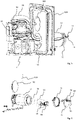
- FIG 3 a sensor arrangement according to the invention for a production facility is shown, for example for the rotary tablet press 100 from FIGS Figures 1 and 2 .
- the sensor device comprises a sensor with an emitting and/or receiving section 50 for emitting and/or receiving sensor signals, as well as a sensor section 52.
- An annular sealing section 54 is arranged between the emitting and/or receiving section 50 and the sensor section 52, on which a sealing hose 56 is held with a first annular end 58 in a sealing manner, in this case clamping.
- a second, likewise ring-shaped end 60 of the sealing tube 56 is also clamped to a sealing container 62 accommodating the sensor.
- a sealing ring 64 is arranged on the second end 60 of the sealing hose 56, for example welded on, and is clamped between an end wall of the sealing container 62 forming a first end of the sealing container 62 and a connecting flange 66 of the access opening 108 of the housing 102 of the production facility, here by means of a clamping ring 68.
- the opposite second end of the sealing container 62 has a closure device in the form of a closure flap 70, which is also tightly clamped by means of a clamping ring 72 and a sealing ring 74 to an end wall of the sealing container 62 forming the second end.
- Closing flap 70 has a sealed line bushing 76 through which, in the example shown, an optical waveguide 78 and an electrical supply line 80 are routed and connected to sensor section 52 .
- the emitting and/or receiving section 50 has a cylindrical emitter and/or receiver 51 and a carrying section 53 carrying it. The position of the emitter and/or receiver 51 can be adjusted in the longitudinal direction by means of the carrying section 53 figure 7 to the left and right.
- the emitter and/or receiver 51 can be moved precisely to the desired position inside the housing.
- the optical waveguide 78 and the electrical supply line 80 are first passed through the line bushing 76 and connected to the sensor section 52 of the sensor.
- the sealing hose 56 is attached with its first end 58 to the annular sealing section 54 and with its second end 60 to the first end of the sealing container 62 in a sealing manner. This attachment can be done in the course of attaching the sealing canister 62 to the access opening 108 of the housing 102 .
- the sensor with the sealing hose 56 and the optical waveguide 78 and the supply line 80 are inserted into the sealing container 62 .
- the state of the sealing container 62 attached to the housing 102 is in figure 4 shown.
- the closure opening in the form of the rapid transfer port is opened from inside the housing 102 using the glove ports explained, with a corresponding closure flap 82 on the sealing container 62 also being opened, so that a passage is created between the interior of the sealing container 62 and the interior of the Housing 102 is formed.
- the sensor can then be transferred from the inside of the housing 102, for example via the glove ports, out of the sealing container 62 into the inside of the housing 102 and arranged at the desired position inside the housing 102, for example on the filling device 22.
- the sealing hose 56 is turned inside out.
- the state of the sensor arranged inside the housing 102 is in figure 5 shown.
- the sensor can be transferred back out of the interior of the housing 102 in the reverse order.
- the sensor can in turn be transferred from the interior of the housing back into the sealing container 62, for example via the glove ports.
- the closure opening 108 and thus also the closure flap 82 of the sealing container 62 are then tightly closed.
- the closing flap 70 can then be opened first by loosening the clamping ring 72 at the second end of the sealing container 62 , so that the supply line 80 and the optical waveguide 78 can be detached from the sensor section 52 .
- the sensor can then be removed through the second end from the sealing container 62 , which is still arranged on the housing 102 , for example.
- the sealing hose 56 can be severed, for example using a clip and cut or heat seal and cut method and closed again in the process be like this in figure 6 is shown.
- the sensor with the sealing tube 56 which has been reduced in size by cutting it off, can be easily removed, e.g. B. be transported to a cleaning room, where the emitting and/or receiving section 50 of the sensor that has come into contact with the powder product can be cleaned.
Landscapes
- Engineering & Computer Science (AREA)
- Mechanical Engineering (AREA)
- Physics & Mathematics (AREA)
- General Physics & Mathematics (AREA)
- Medical Preparation Storing Or Oral Administration Devices (AREA)
- Packaging Frangible Articles (AREA)
- Testing Or Calibration Of Command Recording Devices (AREA)
Applications Claiming Priority (1)
| Application Number | Priority Date | Filing Date | Title |
|---|---|---|---|
| DE102020125653.1A DE102020125653B3 (de) | 2020-10-01 | 2020-10-01 | Sensoranordnung für eine Produktionseinrichtung sowie Verfahren zum Transferieren eines Sensors in ein Gehäuse einer Produktionseinrichtung und aus einem Gehäuse einer Produktionseinrichtung |
Publications (2)
| Publication Number | Publication Date |
|---|---|
| EP3978882A1 true EP3978882A1 (fr) | 2022-04-06 |
| EP3978882B1 EP3978882B1 (fr) | 2023-09-06 |
Family
ID=78086202
Family Applications (1)
| Application Number | Title | Priority Date | Filing Date |
|---|---|---|---|
| EP21197732.7A Active EP3978882B1 (fr) | 2020-10-01 | 2021-09-20 | Agencement de capteur pour un dispositif de production, ainsi que procédé de transfert d'un capteur vers un boîtier d'un dispositif de production et à partir d'un boîtier d'un dispositif de production |
Country Status (7)
| Country | Link |
|---|---|
| US (1) | US11499850B2 (fr) |
| EP (1) | EP3978882B1 (fr) |
| JP (1) | JP7344939B2 (fr) |
| CN (1) | CN114272131B (fr) |
| DE (1) | DE102020125653B3 (fr) |
| DK (1) | DK3978882T3 (fr) |
| ES (1) | ES2965661T3 (fr) |
Families Citing this family (3)
| Publication number | Priority date | Publication date | Assignee | Title |
|---|---|---|---|---|
| DE102023116934B4 (de) * | 2023-06-27 | 2025-12-24 | Fette Compacting Gmbh | Rundläuferpresse und Verfahren zum Vorreinigen des Pressengehäuses einer Rundläuferpresse |
| DE102023135488A1 (de) * | 2023-12-18 | 2025-06-18 | Fette Compacting Gmbh | Vorrichtung und Verfahren zum Entstauben von Tabletten oder Kapseln |
| EP4644896A1 (fr) * | 2024-05-03 | 2025-11-05 | Fette Compacting GmbH | Dispositif d'étalonnage et procédé d'étalonnage d'un capteur de comprimés pour une presse à comprimés |
Citations (4)
| Publication number | Priority date | Publication date | Assignee | Title |
|---|---|---|---|---|
| EP1568480A2 (fr) | 2004-02-20 | 2005-08-31 | Fette GmbH | Méthode et dispositif pour le contrôle de qualité dans la fabrication de comprimés |
| DE102005060676A1 (de) * | 2005-12-19 | 2007-06-21 | Asm Automation Sensorik Messtechnik Gmbh | Positionssensor in Stabbauweise sowie Verfahren zum Austausch |
| US8511160B2 (en) * | 2011-03-31 | 2013-08-20 | Qualitrol Company, Llc | Combined hydrogen and pressure sensor assembly |
| DE102016202315A1 (de) * | 2016-02-16 | 2017-08-17 | Voith Patent Gmbh | Getriebesensoranschlusssystem und Getriebe mit einem solchen System |
Family Cites Families (11)
| Publication number | Priority date | Publication date | Assignee | Title |
|---|---|---|---|---|
| US6692457B2 (en) * | 2002-03-01 | 2004-02-17 | Insulet Corporation | Flow condition sensor assembly for patient infusion device |
| DE10316024A1 (de) * | 2003-02-12 | 2004-08-26 | Fa. Krämer GmbH Elektronik | Vorrichtung zur Qualitätskontrolle fester, pharmazeutischer Erzeugnisse |
| DE102004063085A1 (de) * | 2004-12-28 | 2006-07-06 | Robert Bosch Gmbh | Gasmessfühler |
| CN101443182B (zh) * | 2006-05-11 | 2012-03-28 | Ima基利安有限两合公司 | 带有清洗装置的旋转式压片机及用于该压片机的转子 |
| DE202007003176U1 (de) * | 2007-03-01 | 2007-10-18 | Ima Kilian Gmbh & Co.Kg | Rotationstablettenpresse mit Wascheinrichtung |
| EP2019306A1 (fr) * | 2007-07-24 | 2009-01-28 | Uhlmann VisioTec GmbH | Système destiné à la fabrication et la surveillance de tablettes |
| JP5073443B2 (ja) * | 2007-10-16 | 2012-11-14 | 株式会社畑鉄工所 | 回転式粉末圧縮成型方法及びその装置 |
| JP5918808B2 (ja) | 2014-06-23 | 2016-05-18 | ジーイーエイ・ファーマ・システムズ・リミテッド | 錠剤の製造モジュール及び錠剤の連続製造方法 |
| DE102016111214B3 (de) * | 2016-06-20 | 2017-06-29 | Ancosys Gmbh | Vorrichtung zur Pulverdosierung für chemische Produktionsprozesse unter Reinraumbedingungen, Verwendung derselben und Zudosierungsverfahren |
| EP3421850A1 (fr) * | 2017-06-30 | 2019-01-02 | VAT Holding AG | Soupape à vide comprenant un capteur de position |
| DE102018117351B4 (de) * | 2018-07-18 | 2020-11-05 | Fette Compacting Gmbh | Weiche eines Tablettenablaufs einer Tablettenpresse |
-
2020
- 2020-10-01 DE DE102020125653.1A patent/DE102020125653B3/de not_active Expired - Fee Related
-
2021
- 2021-08-26 JP JP2021138285A patent/JP7344939B2/ja active Active
- 2021-09-20 ES ES21197732T patent/ES2965661T3/es active Active
- 2021-09-20 DK DK21197732.7T patent/DK3978882T3/da active
- 2021-09-20 EP EP21197732.7A patent/EP3978882B1/fr active Active
- 2021-09-28 CN CN202111139786.1A patent/CN114272131B/zh active Active
- 2021-09-30 US US17/490,053 patent/US11499850B2/en active Active
Patent Citations (4)
| Publication number | Priority date | Publication date | Assignee | Title |
|---|---|---|---|---|
| EP1568480A2 (fr) | 2004-02-20 | 2005-08-31 | Fette GmbH | Méthode et dispositif pour le contrôle de qualité dans la fabrication de comprimés |
| DE102005060676A1 (de) * | 2005-12-19 | 2007-06-21 | Asm Automation Sensorik Messtechnik Gmbh | Positionssensor in Stabbauweise sowie Verfahren zum Austausch |
| US8511160B2 (en) * | 2011-03-31 | 2013-08-20 | Qualitrol Company, Llc | Combined hydrogen and pressure sensor assembly |
| DE102016202315A1 (de) * | 2016-02-16 | 2017-08-17 | Voith Patent Gmbh | Getriebesensoranschlusssystem und Getriebe mit einem solchen System |
Also Published As
| Publication number | Publication date |
|---|---|
| DK3978882T3 (da) | 2023-12-11 |
| ES2965661T3 (es) | 2024-04-16 |
| DE102020125653B3 (de) | 2021-11-04 |
| CN114272131A (zh) | 2022-04-05 |
| US20220107210A1 (en) | 2022-04-07 |
| JP2022059567A (ja) | 2022-04-13 |
| EP3978882B1 (fr) | 2023-09-06 |
| CN114272131B (zh) | 2024-07-09 |
| JP7344939B2 (ja) | 2023-09-14 |
| US11499850B2 (en) | 2022-11-15 |
Similar Documents
| Publication | Publication Date | Title |
|---|---|---|
| EP3978882B1 (fr) | Agencement de capteur pour un dispositif de production, ainsi que procédé de transfert d'un capteur vers un boîtier d'un dispositif de production et à partir d'un boîtier d'un dispositif de production | |
| EP4217111B1 (fr) | Composant bêta d'un système de transfert pour une zone d'isolation stérile, zone d'isolation stérile, équipement de remplissage aseptique et procédé de fonctionnement de cet équipement de remplissage | |
| EP2024236B1 (fr) | Machine à emballer | |
| EP1918209B1 (fr) | Procédé destiné au fonctionnement d'une station de déballage | |
| EP3941652B1 (fr) | Dispositif de manipulation de produits sensibles, notamment dispositif de conditionnement | |
| DE202006006930U1 (de) | Verbinder und Verbindersystem | |
| EP2567201B1 (fr) | Balance à dispositif de calibrage | |
| DE102023111480A1 (de) | System zum Verarbeiten von pharmazeutischen Behältern und Verfahren zum Betreiben eines derartigen Systems | |
| DE602004005339T2 (de) | Verfahren und vorrichtung zur abdeckung des raums einer verpackungsmaschine | |
| EP1837643A2 (fr) | Dispositif d'analyse, notamment d'analyse photométrique ou spectrophotométrique | |
| EP2335886B1 (fr) | Agencement de traitement de matières présentant un danger de contamination | |
| DE102005062715B4 (de) | Vorrichtung zum Befüllen von Aufnahmebehältern mit den Produkten einer Rundläuferpresse | |
| EP2883526A1 (fr) | Système de traitement pour poudre et procédé de traitement de poudre | |
| DE102014208550A1 (de) | Reinigung einer Blisterverpackungsmaschine | |
| EP3464164B1 (fr) | Système de remplissage de cuves avec récipient intermédiaire | |
| DE102013110292B4 (de) | Vorrichtung zum Koppeln von zwei Behältern | |
| EP3825017B1 (fr) | Système de traitement pour poudre et procédé de décontamination d'un tel système de traitement | |
| DE69206664T2 (de) | Automatische Anlage zum Fördern und Wiegen von mit einer radioaktiven Flüssigkeit gefüllten Flaschen zwischen einer Entnahmevorrichtung und einer Analysevorrichtung | |
| WO2023280509A1 (fr) | Dispositif de protection, ensemble de protection pour récipient et procédé de raccordement d'un dispositif de protection à un récipient | |
| DE102010060241B4 (de) | Probenehmer | |
| DE4023839A1 (de) | Vorrichtung zum entnehmen von gas- und/oder fluessigkeitsproben aus dem sicherheitsbehaelter von kernkraftwerken | |
| DE102009027750A1 (de) | Probenehmer | |
| WO2009138328A1 (fr) | Dispositif de remplissage et procédé de remplissage de récipients | |
| EP4240653A1 (fr) | Appareil de fermeture pour fermer des récipients pharmaceutiques | |
| DE10355810B4 (de) | System zur Reinigung eines Prozessraumes eines Isolators |
Legal Events
| Date | Code | Title | Description |
|---|---|---|---|
| PUAI | Public reference made under article 153(3) epc to a published international application that has entered the european phase |
Free format text: ORIGINAL CODE: 0009012 |
|
| STAA | Information on the status of an ep patent application or granted ep patent |
Free format text: STATUS: THE APPLICATION HAS BEEN PUBLISHED |
|
| AK | Designated contracting states |
Kind code of ref document: A1 Designated state(s): AL AT BE BG CH CY CZ DE DK EE ES FI FR GB GR HR HU IE IS IT LI LT LU LV MC MK MT NL NO PL PT RO RS SE SI SK SM TR |
|
| STAA | Information on the status of an ep patent application or granted ep patent |
Free format text: STATUS: REQUEST FOR EXAMINATION WAS MADE |
|
| 17P | Request for examination filed |
Effective date: 20220913 |
|
| RBV | Designated contracting states (corrected) |
Designated state(s): AL AT BE BG CH CY CZ DE DK EE ES FI FR GB GR HR HU IE IS IT LI LT LU LV MC MK MT NL NO PL PT RO RS SE SI SK SM TR |
|
| GRAP | Despatch of communication of intention to grant a patent |
Free format text: ORIGINAL CODE: EPIDOSNIGR1 |
|
| STAA | Information on the status of an ep patent application or granted ep patent |
Free format text: STATUS: GRANT OF PATENT IS INTENDED |
|
| INTG | Intention to grant announced |
Effective date: 20230215 |
|
| GRAJ | Information related to disapproval of communication of intention to grant by the applicant or resumption of examination proceedings by the epo deleted |
Free format text: ORIGINAL CODE: EPIDOSDIGR1 |
|
| STAA | Information on the status of an ep patent application or granted ep patent |
Free format text: STATUS: REQUEST FOR EXAMINATION WAS MADE |
|
| GRAP | Despatch of communication of intention to grant a patent |
Free format text: ORIGINAL CODE: EPIDOSNIGR1 |
|
| STAA | Information on the status of an ep patent application or granted ep patent |
Free format text: STATUS: GRANT OF PATENT IS INTENDED |
|
| INTC | Intention to grant announced (deleted) | ||
| INTG | Intention to grant announced |
Effective date: 20230411 |
|
| P01 | Opt-out of the competence of the unified patent court (upc) registered |
Effective date: 20230530 |
|
| GRAS | Grant fee paid |
Free format text: ORIGINAL CODE: EPIDOSNIGR3 |
|
| GRAA | (expected) grant |
Free format text: ORIGINAL CODE: 0009210 |
|
| STAA | Information on the status of an ep patent application or granted ep patent |
Free format text: STATUS: THE PATENT HAS BEEN GRANTED |
|
| AK | Designated contracting states |
Kind code of ref document: B1 Designated state(s): AL AT BE BG CH CY CZ DE DK EE ES FI FR GB GR HR HU IE IS IT LI LT LU LV MC MK MT NL NO PL PT RO RS SE SI SK SM TR |
|
| REG | Reference to a national code |
Ref country code: GB Ref legal event code: FG4D Free format text: NOT ENGLISH |
|
| REG | Reference to a national code |
Ref country code: CH Ref legal event code: EP |
|
| REG | Reference to a national code |
Ref country code: IE Ref legal event code: FG4D Free format text: LANGUAGE OF EP DOCUMENT: GERMAN |
|
| REG | Reference to a national code |
Ref country code: DE Ref legal event code: R096 Ref document number: 502021001427 Country of ref document: DE |
|
| REG | Reference to a national code |
Ref country code: SE Ref legal event code: TRGR |
|
| REG | Reference to a national code |
Ref country code: DK Ref legal event code: T3 Effective date: 20231205 |
|
| REG | Reference to a national code |
Ref country code: LT Ref legal event code: MG9D |
|
| REG | Reference to a national code |
Ref country code: NL Ref legal event code: MP Effective date: 20230906 |
|
| PG25 | Lapsed in a contracting state [announced via postgrant information from national office to epo] |
Ref country code: GR Free format text: LAPSE BECAUSE OF FAILURE TO SUBMIT A TRANSLATION OF THE DESCRIPTION OR TO PAY THE FEE WITHIN THE PRESCRIBED TIME-LIMIT Effective date: 20231207 |
|
| PG25 | Lapsed in a contracting state [announced via postgrant information from national office to epo] |
Ref country code: RS Free format text: LAPSE BECAUSE OF FAILURE TO SUBMIT A TRANSLATION OF THE DESCRIPTION OR TO PAY THE FEE WITHIN THE PRESCRIBED TIME-LIMIT Effective date: 20230906 Ref country code: NO Free format text: LAPSE BECAUSE OF FAILURE TO SUBMIT A TRANSLATION OF THE DESCRIPTION OR TO PAY THE FEE WITHIN THE PRESCRIBED TIME-LIMIT Effective date: 20231206 Ref country code: LV Free format text: LAPSE BECAUSE OF FAILURE TO SUBMIT A TRANSLATION OF THE DESCRIPTION OR TO PAY THE FEE WITHIN THE PRESCRIBED TIME-LIMIT Effective date: 20230906 Ref country code: LT Free format text: LAPSE BECAUSE OF FAILURE TO SUBMIT A TRANSLATION OF THE DESCRIPTION OR TO PAY THE FEE WITHIN THE PRESCRIBED TIME-LIMIT Effective date: 20230906 Ref country code: HR Free format text: LAPSE BECAUSE OF FAILURE TO SUBMIT A TRANSLATION OF THE DESCRIPTION OR TO PAY THE FEE WITHIN THE PRESCRIBED TIME-LIMIT Effective date: 20230906 Ref country code: GR Free format text: LAPSE BECAUSE OF FAILURE TO SUBMIT A TRANSLATION OF THE DESCRIPTION OR TO PAY THE FEE WITHIN THE PRESCRIBED TIME-LIMIT Effective date: 20231207 Ref country code: FI Free format text: LAPSE BECAUSE OF FAILURE TO SUBMIT A TRANSLATION OF THE DESCRIPTION OR TO PAY THE FEE WITHIN THE PRESCRIBED TIME-LIMIT Effective date: 20230906 |
|
| PG25 | Lapsed in a contracting state [announced via postgrant information from national office to epo] |
Ref country code: NL Free format text: LAPSE BECAUSE OF FAILURE TO SUBMIT A TRANSLATION OF THE DESCRIPTION OR TO PAY THE FEE WITHIN THE PRESCRIBED TIME-LIMIT Effective date: 20230906 |
|
| PG25 | Lapsed in a contracting state [announced via postgrant information from national office to epo] |
Ref country code: IS Free format text: LAPSE BECAUSE OF FAILURE TO SUBMIT A TRANSLATION OF THE DESCRIPTION OR TO PAY THE FEE WITHIN THE PRESCRIBED TIME-LIMIT Effective date: 20240106 |
|
| REG | Reference to a national code |
Ref country code: ES Ref legal event code: FG2A Ref document number: 2965661 Country of ref document: ES Kind code of ref document: T3 Effective date: 20240416 |
|
| PG25 | Lapsed in a contracting state [announced via postgrant information from national office to epo] |
Ref country code: SM Free format text: LAPSE BECAUSE OF FAILURE TO SUBMIT A TRANSLATION OF THE DESCRIPTION OR TO PAY THE FEE WITHIN THE PRESCRIBED TIME-LIMIT Effective date: 20230906 Ref country code: RO Free format text: LAPSE BECAUSE OF FAILURE TO SUBMIT A TRANSLATION OF THE DESCRIPTION OR TO PAY THE FEE WITHIN THE PRESCRIBED TIME-LIMIT Effective date: 20230906 Ref country code: IS Free format text: LAPSE BECAUSE OF FAILURE TO SUBMIT A TRANSLATION OF THE DESCRIPTION OR TO PAY THE FEE WITHIN THE PRESCRIBED TIME-LIMIT Effective date: 20240106 Ref country code: EE Free format text: LAPSE BECAUSE OF FAILURE TO SUBMIT A TRANSLATION OF THE DESCRIPTION OR TO PAY THE FEE WITHIN THE PRESCRIBED TIME-LIMIT Effective date: 20230906 Ref country code: CZ Free format text: LAPSE BECAUSE OF FAILURE TO SUBMIT A TRANSLATION OF THE DESCRIPTION OR TO PAY THE FEE WITHIN THE PRESCRIBED TIME-LIMIT Effective date: 20230906 Ref country code: SK Free format text: LAPSE BECAUSE OF FAILURE TO SUBMIT A TRANSLATION OF THE DESCRIPTION OR TO PAY THE FEE WITHIN THE PRESCRIBED TIME-LIMIT Effective date: 20230906 Ref country code: PT Free format text: LAPSE BECAUSE OF FAILURE TO SUBMIT A TRANSLATION OF THE DESCRIPTION OR TO PAY THE FEE WITHIN THE PRESCRIBED TIME-LIMIT Effective date: 20240108 |
|
| PG25 | Lapsed in a contracting state [announced via postgrant information from national office to epo] |
Ref country code: LU Free format text: LAPSE BECAUSE OF NON-PAYMENT OF DUE FEES Effective date: 20230920 |
|
| PG25 | Lapsed in a contracting state [announced via postgrant information from national office to epo] |
Ref country code: PL Free format text: LAPSE BECAUSE OF FAILURE TO SUBMIT A TRANSLATION OF THE DESCRIPTION OR TO PAY THE FEE WITHIN THE PRESCRIBED TIME-LIMIT Effective date: 20230906 Ref country code: LU Free format text: LAPSE BECAUSE OF NON-PAYMENT OF DUE FEES Effective date: 20230920 |
|
| REG | Reference to a national code |
Ref country code: DE Ref legal event code: R097 Ref document number: 502021001427 Country of ref document: DE |
|
| PG25 | Lapsed in a contracting state [announced via postgrant information from national office to epo] |
Ref country code: MC Free format text: LAPSE BECAUSE OF FAILURE TO SUBMIT A TRANSLATION OF THE DESCRIPTION OR TO PAY THE FEE WITHIN THE PRESCRIBED TIME-LIMIT Effective date: 20230906 |
|
| REG | Reference to a national code |
Ref country code: IE Ref legal event code: MM4A |
|
| PG25 | Lapsed in a contracting state [announced via postgrant information from national office to epo] |
Ref country code: IE Free format text: LAPSE BECAUSE OF NON-PAYMENT OF DUE FEES Effective date: 20230920 |
|
| PLBE | No opposition filed within time limit |
Free format text: ORIGINAL CODE: 0009261 |
|
| STAA | Information on the status of an ep patent application or granted ep patent |
Free format text: STATUS: NO OPPOSITION FILED WITHIN TIME LIMIT |
|
| PG25 | Lapsed in a contracting state [announced via postgrant information from national office to epo] |
Ref country code: MC Free format text: LAPSE BECAUSE OF FAILURE TO SUBMIT A TRANSLATION OF THE DESCRIPTION OR TO PAY THE FEE WITHIN THE PRESCRIBED TIME-LIMIT Effective date: 20230906 Ref country code: IE Free format text: LAPSE BECAUSE OF NON-PAYMENT OF DUE FEES Effective date: 20230920 Ref country code: SI Free format text: LAPSE BECAUSE OF FAILURE TO SUBMIT A TRANSLATION OF THE DESCRIPTION OR TO PAY THE FEE WITHIN THE PRESCRIBED TIME-LIMIT Effective date: 20230906 |
|
| 26N | No opposition filed |
Effective date: 20240607 |
|
| PG25 | Lapsed in a contracting state [announced via postgrant information from national office to epo] |
Ref country code: BG Free format text: LAPSE BECAUSE OF FAILURE TO SUBMIT A TRANSLATION OF THE DESCRIPTION OR TO PAY THE FEE WITHIN THE PRESCRIBED TIME-LIMIT Effective date: 20230906 |
|
| PG25 | Lapsed in a contracting state [announced via postgrant information from national office to epo] |
Ref country code: BG Free format text: LAPSE BECAUSE OF FAILURE TO SUBMIT A TRANSLATION OF THE DESCRIPTION OR TO PAY THE FEE WITHIN THE PRESCRIBED TIME-LIMIT Effective date: 20230906 |
|
| PG25 | Lapsed in a contracting state [announced via postgrant information from national office to epo] |
Ref country code: CY Free format text: LAPSE BECAUSE OF FAILURE TO SUBMIT A TRANSLATION OF THE DESCRIPTION OR TO PAY THE FEE WITHIN THE PRESCRIBED TIME-LIMIT; INVALID AB INITIO Effective date: 20210920 |
|
| PG25 | Lapsed in a contracting state [announced via postgrant information from national office to epo] |
Ref country code: HU Free format text: LAPSE BECAUSE OF FAILURE TO SUBMIT A TRANSLATION OF THE DESCRIPTION OR TO PAY THE FEE WITHIN THE PRESCRIBED TIME-LIMIT; INVALID AB INITIO Effective date: 20210920 |
|
| REG | Reference to a national code |
Ref country code: CH Ref legal event code: U11 Free format text: ST27 STATUS EVENT CODE: U-0-0-U10-U11 (AS PROVIDED BY THE NATIONAL OFFICE) Effective date: 20251001 |
|
| PGFP | Annual fee paid to national office [announced via postgrant information from national office to epo] |
Ref country code: DK Payment date: 20250922 Year of fee payment: 5 |
|
| PGFP | Annual fee paid to national office [announced via postgrant information from national office to epo] |
Ref country code: GB Payment date: 20250923 Year of fee payment: 5 Ref country code: BE Payment date: 20250919 Year of fee payment: 5 |
|
| PGFP | Annual fee paid to national office [announced via postgrant information from national office to epo] |
Ref country code: FR Payment date: 20250926 Year of fee payment: 5 Ref country code: AT Payment date: 20251020 Year of fee payment: 5 |
|
| PGFP | Annual fee paid to national office [announced via postgrant information from national office to epo] |
Ref country code: SE Payment date: 20250922 Year of fee payment: 5 |
|
| PG25 | Lapsed in a contracting state [announced via postgrant information from national office to epo] |
Ref country code: TR Free format text: LAPSE BECAUSE OF FAILURE TO SUBMIT A TRANSLATION OF THE DESCRIPTION OR TO PAY THE FEE WITHIN THE PRESCRIBED TIME-LIMIT Effective date: 20230906 |
|
| PGFP | Annual fee paid to national office [announced via postgrant information from national office to epo] |
Ref country code: DE Payment date: 20251111 Year of fee payment: 5 |
|
| PGFP | Annual fee paid to national office [announced via postgrant information from national office to epo] |
Ref country code: IT Payment date: 20250930 Year of fee payment: 5 |
|
| PGFP | Annual fee paid to national office [announced via postgrant information from national office to epo] |
Ref country code: CH Payment date: 20251001 Year of fee payment: 5 |
|
| PGFP | Annual fee paid to national office [announced via postgrant information from national office to epo] |
Ref country code: ES Payment date: 20251020 Year of fee payment: 5 |