EP3978948A1 - Unité radar et procédé de fonctionnement correspondant - Google Patents
Unité radar et procédé de fonctionnement correspondant Download PDFInfo
- Publication number
- EP3978948A1 EP3978948A1 EP20306155.1A EP20306155A EP3978948A1 EP 3978948 A1 EP3978948 A1 EP 3978948A1 EP 20306155 A EP20306155 A EP 20306155A EP 3978948 A1 EP3978948 A1 EP 3978948A1
- Authority
- EP
- European Patent Office
- Prior art keywords
- receiver
- radar
- mode
- radar unit
- channel
- Prior art date
- Legal status (The legal status is an assumption and is not a legal conclusion. Google has not performed a legal analysis and makes no representation as to the accuracy of the status listed.)
- Pending
Links
- 238000011017 operating method Methods 0.000 title description 3
- 238000000034 method Methods 0.000 claims abstract description 18
- 238000004891 communication Methods 0.000 claims description 5
- 238000001514 detection method Methods 0.000 description 7
- 239000003990 capacitor Substances 0.000 description 5
- XUIMIQQOPSSXEZ-UHFFFAOYSA-N Silicon Chemical compound [Si] XUIMIQQOPSSXEZ-UHFFFAOYSA-N 0.000 description 4
- 230000003247 decreasing effect Effects 0.000 description 4
- 238000005516 engineering process Methods 0.000 description 4
- 230000008569 process Effects 0.000 description 4
- 229910052710 silicon Inorganic materials 0.000 description 4
- 239000010703 silicon Substances 0.000 description 4
- 238000013461 design Methods 0.000 description 3
- 230000010354 integration Effects 0.000 description 3
- 238000004513 sizing Methods 0.000 description 3
- 229910000577 Silicon-germanium Inorganic materials 0.000 description 2
- 230000005540 biological transmission Effects 0.000 description 2
- 238000011161 development Methods 0.000 description 2
- 238000004519 manufacturing process Methods 0.000 description 2
- 238000005259 measurement Methods 0.000 description 2
- 230000009467 reduction Effects 0.000 description 2
- 230000008054 signal transmission Effects 0.000 description 2
- LEVVHYCKPQWKOP-UHFFFAOYSA-N [Si].[Ge] Chemical compound [Si].[Ge] LEVVHYCKPQWKOP-UHFFFAOYSA-N 0.000 description 1
- 230000008901 benefit Effects 0.000 description 1
- 230000008859 change Effects 0.000 description 1
- 230000000295 complement effect Effects 0.000 description 1
- 230000001419 dependent effect Effects 0.000 description 1
- 230000000694 effects Effects 0.000 description 1
- 238000011156 evaluation Methods 0.000 description 1
- 238000002955 isolation Methods 0.000 description 1
- 230000010363 phase shift Effects 0.000 description 1
- 239000004065 semiconductor Substances 0.000 description 1
Images





Classifications
-
- G—PHYSICS
- G01—MEASURING; TESTING
- G01S—RADIO DIRECTION-FINDING; RADIO NAVIGATION; DETERMINING DISTANCE OR VELOCITY BY USE OF RADIO WAVES; LOCATING OR PRESENCE-DETECTING BY USE OF THE REFLECTION OR RERADIATION OF RADIO WAVES; ANALOGOUS ARRANGEMENTS USING OTHER WAVES
- G01S7/00—Details of systems according to groups G01S13/00, G01S15/00, G01S17/00
- G01S7/02—Details of systems according to groups G01S13/00, G01S15/00, G01S17/00 of systems according to group G01S13/00
- G01S7/35—Details of non-pulse systems
- G01S7/352—Receivers
-
- G—PHYSICS
- G01—MEASURING; TESTING
- G01S—RADIO DIRECTION-FINDING; RADIO NAVIGATION; DETERMINING DISTANCE OR VELOCITY BY USE OF RADIO WAVES; LOCATING OR PRESENCE-DETECTING BY USE OF THE REFLECTION OR RERADIATION OF RADIO WAVES; ANALOGOUS ARRANGEMENTS USING OTHER WAVES
- G01S7/00—Details of systems according to groups G01S13/00, G01S15/00, G01S17/00
- G01S7/02—Details of systems according to groups G01S13/00, G01S15/00, G01S17/00 of systems according to group G01S13/00
- G01S7/28—Details of pulse systems
- G01S7/285—Receivers
- G01S7/288—Coherent receivers
-
- G—PHYSICS
- G01—MEASURING; TESTING
- G01S—RADIO DIRECTION-FINDING; RADIO NAVIGATION; DETERMINING DISTANCE OR VELOCITY BY USE OF RADIO WAVES; LOCATING OR PRESENCE-DETECTING BY USE OF THE REFLECTION OR RERADIATION OF RADIO WAVES; ANALOGOUS ARRANGEMENTS USING OTHER WAVES
- G01S13/00—Systems using the reflection or reradiation of radio waves, e.g. radar systems; Analogous systems using reflection or reradiation of waves whose nature or wavelength is irrelevant or unspecified
- G01S13/02—Systems using reflection of radio waves, e.g. primary radar systems; Analogous systems
- G01S13/06—Systems determining position data of a target
- G01S13/08—Systems for measuring distance only
- G01S13/32—Systems for measuring distance only using transmission of continuous waves, whether amplitude-, frequency-, or phase-modulated, or unmodulated
- G01S13/34—Systems for measuring distance only using transmission of continuous waves, whether amplitude-, frequency-, or phase-modulated, or unmodulated using transmission of continuous, frequency-modulated waves while heterodyning the received signal, or a signal derived therefrom, with a locally-generated signal related to the contemporaneously transmitted signal
-
- G—PHYSICS
- G01—MEASURING; TESTING
- G01S—RADIO DIRECTION-FINDING; RADIO NAVIGATION; DETERMINING DISTANCE OR VELOCITY BY USE OF RADIO WAVES; LOCATING OR PRESENCE-DETECTING BY USE OF THE REFLECTION OR RERADIATION OF RADIO WAVES; ANALOGOUS ARRANGEMENTS USING OTHER WAVES
- G01S13/00—Systems using the reflection or reradiation of radio waves, e.g. radar systems; Analogous systems using reflection or reradiation of waves whose nature or wavelength is irrelevant or unspecified
- G01S13/88—Radar or analogous systems specially adapted for specific applications
- G01S13/93—Radar or analogous systems specially adapted for specific applications for anti-collision purposes
- G01S13/931—Radar or analogous systems specially adapted for specific applications for anti-collision purposes of land vehicles
-
- G—PHYSICS
- G01—MEASURING; TESTING
- G01S—RADIO DIRECTION-FINDING; RADIO NAVIGATION; DETERMINING DISTANCE OR VELOCITY BY USE OF RADIO WAVES; LOCATING OR PRESENCE-DETECTING BY USE OF THE REFLECTION OR RERADIATION OF RADIO WAVES; ANALOGOUS ARRANGEMENTS USING OTHER WAVES
- G01S7/00—Details of systems according to groups G01S13/00, G01S15/00, G01S17/00
- G01S7/02—Details of systems according to groups G01S13/00, G01S15/00, G01S17/00 of systems according to group G01S13/00
- G01S7/03—Details of HF subsystems specially adapted therefor, e.g. common to transmitter and receiver
- G01S7/032—Constructional details for solid-state radar subsystems
-
- G—PHYSICS
- G01—MEASURING; TESTING
- G01S—RADIO DIRECTION-FINDING; RADIO NAVIGATION; DETERMINING DISTANCE OR VELOCITY BY USE OF RADIO WAVES; LOCATING OR PRESENCE-DETECTING BY USE OF THE REFLECTION OR RERADIATION OF RADIO WAVES; ANALOGOUS ARRANGEMENTS USING OTHER WAVES
- G01S7/00—Details of systems according to groups G01S13/00, G01S15/00, G01S17/00
- G01S7/02—Details of systems according to groups G01S13/00, G01S15/00, G01S17/00 of systems according to group G01S13/00
- G01S7/28—Details of pulse systems
- G01S7/285—Receivers
- G01S7/292—Extracting wanted echo-signals
-
- G—PHYSICS
- G01—MEASURING; TESTING
- G01S—RADIO DIRECTION-FINDING; RADIO NAVIGATION; DETERMINING DISTANCE OR VELOCITY BY USE OF RADIO WAVES; LOCATING OR PRESENCE-DETECTING BY USE OF THE REFLECTION OR RERADIATION OF RADIO WAVES; ANALOGOUS ARRANGEMENTS USING OTHER WAVES
- G01S7/00—Details of systems according to groups G01S13/00, G01S15/00, G01S17/00
- G01S7/02—Details of systems according to groups G01S13/00, G01S15/00, G01S17/00 of systems according to group G01S13/00
- G01S7/35—Details of non-pulse systems
- G01S7/352—Receivers
- G01S7/354—Extracting wanted echo-signals
-
- G—PHYSICS
- G01—MEASURING; TESTING
- G01S—RADIO DIRECTION-FINDING; RADIO NAVIGATION; DETERMINING DISTANCE OR VELOCITY BY USE OF RADIO WAVES; LOCATING OR PRESENCE-DETECTING BY USE OF THE REFLECTION OR RERADIATION OF RADIO WAVES; ANALOGOUS ARRANGEMENTS USING OTHER WAVES
- G01S7/00—Details of systems according to groups G01S13/00, G01S15/00, G01S17/00
- G01S7/02—Details of systems according to groups G01S13/00, G01S15/00, G01S17/00 of systems according to group G01S13/00
- G01S7/35—Details of non-pulse systems
- G01S7/352—Receivers
- G01S7/358—Receivers using I/Q processing
Definitions
- the present disclosure relates to a radar unit. Furthermore, the present disclosure relates to a corresponding method of operating a radar unit.
- Automotive radar solutions for advanced driver assistance systems are currently being deployed on a large scale. These solutions can typically be grouped into long-range radar applications (LRR) and short-range radar (SRR) applications. Both of these applications typically use frequency modulated continuous wave (FMCW) modulation techniques in order to be able to identify a radar target, such as a car or a pedestrian. These radar systems typically utilize millimeter wave (mmW) frequencies for transmission and reception.
- LRR long-range radar applications
- SRR short-range radar
- FMCW frequency modulated continuous wave
- mmW millimeter wave
- a radar unit comprising: a receiver circuit configured to receive a radar signal; a controller configured to control said receiver circuit, wherein said controller is configured to cause said receiver circuit to operate either in a complex receiver mode or in a real receiver mode.
- the complex receiver mode corresponds to a long-range radar (LRR) mode of the radar unit and the real receiver mode corresponds to a short-range radar (SRR) mode of the radar unit.
- LRR long-range radar
- SRR short-range radar
- the controller is further configured to cause the receiver circuit to use, in the complex receiver mode, an I-channel and a Q-channel of the received radar signal.
- the controller is further configured to cause the receiver circuit to use, in the real receiver mode, only said I-channel of the received radar signal.
- the controller is configured to cause said receiver circuit to use only said I-channel by shorting the Q-channel to ground.
- the controller is further configured to increase a high-pass filter capacitance of the I-channel and to decrease a high-pass filter resistance of the I-channel when the receiver circuit operates in the real receiver mode.
- the controller is configured to double the high-pass filter capacitance and to divide the high-pass filter resistance by two.
- the controller is configured to increase said high-pass filter capacitance of the I-channel by connecting a high-pass filter capacitance of the Q-channel to said I-channel.
- the controller is configured to decrease the high-pass filter resistance of the I-channel by controlling a variable resistor.
- the controller is configured to cause the receiver unit to alternate between operating in the complex receiver mode and operating in the real receiver mode.
- said alternating comprises switching from the complex receiver mode to the real receiver mode or from the real receiver mode to the complex receiver mode after one or more frames of the received radar signal.
- the receiver circuit includes a millimeter wave (mmW) unit and a baseband unit and said radar signal is an echo signal of a radar signal previously transmitted by the radar unit.
- mmW millimeter wave
- a vehicle comprises a radar unit of the kind set forth.
- a method of operating a radar unit comprising: receiving, by a receiver circuit comprised in the radar unit, a radar signal; controlling, by a controller comprised in said radar unit, said receiver circuit, wherein said controller causes said receiver circuit to operate either in a complex receiver mode or in a real receiver mode.
- the complex receiver mode corresponds to a long-range communication mode of the radar unit and the real receiver mode corresponds to a short-range communication mode of the radar unit.
- LRR long-range radar applications
- SRR short-range radar
- FMCW frequency modulated continuous wave
- mmW millimeter wave
- CMOS complementary metal-oxide-semiconductor
- RF radio frequency
- Both the increased transceiver performance and the increased level of integration facilitate the implementation of different applications, ranging from long-range applications (300 meters or more) to very short-range applications (30 meters or less). It is noted that the same transceiver circuit may be used to support these different applications.
- a transceiver typically contains a signal transmission function or signal transmission unit (i.e., a transmitter) and a signal receiving function or signal receiving unit (i.e., a receiver).
- the noise figure (NF) of the receiver is an important measure of the performance of a radar unit, in the sense that it influences the detection range of the receiver and thus of the radar unit as a whole.
- CMOS complementary metal-oxide-semiconductor
- IF intermediate frequency
- CMOS receivers suffer from a high flicker noise (i.e., a low frequency noise) that can be dominant at medium frequencies (up to 2 MHz). As a consequence, the detection capability at short distances may be negatively affected.
- Advanced radar CMOS receivers are often based on an IQ topology, which facilitates reducing the overall receiver NF by 3dB, mainly at a high intermediate frequency (2 MHz or higher), but at the cost of additional area because baseband (BB) filters and BB variable gain amplifiers (VGAs) have to be implemented as well.
- BB baseband
- VGA variable gain amplifier
- a received signal is divided into an I-component or I-channel and a Q-component or Q-channel.
- the I-channel is the received signal without a phase shift (i.e., the "in-phase" or reference signal), while the Q-channel is the received signal shifted by 90 degrees (i.e., the received signal in quadrature).
- the flicker noise may remain high, which is mainly caused by the use of the active stages of the baseband unit (i.e., the VGAs).
- the VGAs the active stages of the baseband unit
- a relatively simple solution is to increase the capacitance and to reduce the resistance of the filter components.
- the area can only be increased to a certain extent, and it remains difficult to achieve the required performance in terms of an acceptable noise figure at low frequencies.
- CMOS technology allows increasing the receiver bandwidth and increasing the target detection range, it may result in a higher noise figure at low frequencies, which is mainly due to flicker noise generated by the baseband stages (high-pass filter and variable gain amplifiers).
- complex receivers are commonly used. Complex receivers improve, at least theoretically, the receiver's noise figure by around 3dB, but at the cost of a large area, which is mainly attributable the baseband high-pass filter, because the baseband component is duplicated.
- Fig. 1 shows an example of a radar receiver line-up 100.
- the receiver includes a low noise amplifier 102, a mixer 104, a high-pass filter 106, a variable gain amplifier 108, another high-pass filter 110 and another variable gain amplifier 112.
- the mixer 104 is controlled by a local oscillator (LO).
- LO local oscillator
- Fig. 2 shows an example of a receiver circuit performance 200.
- the flicker noise is an important factor, which determines the noise performance of the baseband analog components.
- the radio frequency front end of a receiver circuit RX-RFFE
- the baseband noise has a significant impact on the radar performance, as shown in Fig. 2 .
- the baseband components include a filter and a variable gain amplifier.
- IF intermediate frequency
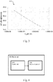
- Fig. 3 shows an example of a noise performance 300 regarding the RC sizing of a high-pass filter.
- the baseband noise management is mainly based on controlling the capacitance of the high-pass filter, as illustrated in Fig. 3 .
- a trade-off should be achieved, because in order to reduce the baseband noise, the capacitance of the high-pass filter (C HPF ) should be increased, but in order to reduce the area (i.e., the silicon footprint), the capacitance of the high-pass filter should be decreased.
- fig. 3 shows the noise performance at an intermediate frequency of 500 kHz, for a 8dB downconverter with a first-order high-pass filter having a variable capacitance.
- a radar unit and a corresponding method of operating a radar unit which facilitate reducing the noise figure at lower frequencies - thus reducing the flicker noise - with minimal or no impact on the area, while increasing the noise figure at higher frequencies.
- This will facilitate increasing the overall performance of the radar unit and it will facilitate properly supporting both long-range radar applications and short-range radar applications.
- Fig. 4 shows an illustrative embodiment of a radar unit 400.
- the radar unit 400 comprises a receiver circuit 402 and a controller 404.
- the receiver circuit 402 is configured to receive a radar signal.
- the receiver circuit 402 may include a millimeter wave (mmW) unit and a baseband unit, and the radar signal may be an echo signal of a radar signal previously transmitted by the radar unit.
- the baseband unit may be used for the demodulation of the radar signal.
- the controller 404 is configured to control the receiver circuit 402. More specifically, the controller 404 is configured to cause the receiver circuit 402 to operate either in a complex receiver mode or in a real receiver mode. In this way, the performance of the radar unit 400 may be increased.
- the radar unit 404 may properly support both long-range radar applications and short-range radar applications.
- the receiver 402 which may be based on an IQ topology, may be programmed or configured to operate as a real receiver temporarily. This may facilitate reducing the noise figure at lower frequencies, thus decreasing the flicker noise, while increasing said noise figure at higher frequencies.
- the complex receiver mode corresponds to a long-range radar (LRR) mode of the radar unit and the real receiver mode corresponds to a short-range radar (SRR) mode of the radar unit.
- LRR long-range radar
- SRR short-range radar
- the controller is further configured to cause the receiver circuit to use, in the complex receiver mode, an I-channel and a Q-channel of the received radar signal. In this way, the receiver circuit may easily be configured or programmed to work in the complex receiver mode.
- the controller is further configured to cause the receiver circuit to use, in the real receiver mode, only said I-channel of the received radar signal. In this way, the receiver circuit may easily be configured or programmed to work in the real receiver mode. Furthermore, in one or more embodiments, the controller is configured to cause said receiver circuit to use only said I-channel by shorting the Q-channel to ground. This further facilitates operating the receiver circuit in the real receiver mode.
- the controller is further configured to increase a high-pass filter capacitance of the I-channel and to decrease a high-pass filter resistance of the I-channel when the receiver circuit operates in the real receiver mode.
- the controller may be configured to double the high-pass filter capacitance and to divide the high-pass filter resistance by two.
- the controller is configured to increase said high-pass filter capacitance of the I-channel by connecting a high-pass filter capacitance of the Q-channel to said I-channel.
- some capacitances of the Q-channel may be reused to change the RC filter of the I-channel when the receiver circuit operates in the real receiver mode, because the Q-channel is no longer used.
- the capacitance C HPF of the Q-channel may be reused in the I-channel, such that the total capacitance of the I-channel becomes 2 ⁇ C HPF .
- the controller is configured to decrease the high-pass filter resistance of the I-channel by controlling a variable resistor. More specifically, as mentioned above, the resistance may be divided by two (R HPF /2), such that the filter cut-off frequency remains the same. This may facilitate decreasing the noise figure at lower frequencies (thus decreasing flicker noise) while increasing it at higher frequencies, with minimal or no impact on the area.
- the controller is configured to cause the receiver unit to alternate between operating in the complex receiver mode and operating in the real receiver mode.
- said alternating comprises switching from the complex receiver mode to the real receiver mode or from the real receiver mode to the complex receiver mode after one or more frames of the received radar signal.
- the radar unit can be configured and reconfigured in a flexible manner, in order to support both long-range detection and short-range detection, without a significant impact on the silicon footprint.
- Fig. 5 shows an illustrative embodiment of a method 500 of operating a radar unit of the kind set forth.
- the method 500 comprises the following steps.
- a receiver circuit comprised in a radar unit receives a radar signal.
- a controller comprised in said radar unit controls said receiver circuit, in particular by causing said receiver circuit to operate either in a complex receiver mode or in a real receiver mode.
- the method 500 facilitates increasing the performance of a radar unit of the kind set forth.
- the presently disclosed radar unit and operating method facilitate trading off a high-frequency noise figure and a low-frequency noise figure by programming the receiver circuit to operate either in the complex receiver mode or in the real receiver mode, depending the radar system requirements.
- the high-pass filter may use the full complex receiver filter capacitance (2C), and half of the resistance (R/2), which facilitates reducing the baseband flicker noise, and consequently the noise figure at low frequencies.
- a programmable complex receiver may be configured to operate as a real receiver, with different resistances and capacitances coupled in the baseband filters, but with the same final cut-off frequency.
- the presently disclosed method of operating a radar unit may be implemented in such a way a sequence of received frames is processed in an interleaved manner. That is to say, one or more frames may be processed by the receiver circuit operating in the complex receiver mode, one or more subsequent frames may be processed by the receiver circuit operating the real receiver mode, one or more further subsequent frames may again be processed by the receiver circuit operating in the complex receiver mode, etc.
- the number of frames after which a switch to the other mode occurs may also be programmable or configurable and depend on the radar system characteristics.
- Fig. 6 shows an illustrative embodiment of a configurable receiver circuit 600.
- the configurable receiver circuit 600 is based on an IQ topology, and comprises a millimeter wave radio frequency front end 602, a reconfigurable high-pass filter 604, a baseband amplifier 606 which includes an amplifier 616 of the I-channel and an amplifier 618 of the Q-channel, an amplifier 608 of the front end, a mixer 610 of the I-channel controlled by a local oscillator, a mixer 612 of the Q-channel controlled by another local oscillator, and a high-pass filter 614.
- a controller (not shown) of the radar unit controls the receiver circuit 600, in particular the high-pass filter 614, in such a way that the circuit either operates in a complex mode (in which both the I-channel and the Q-channel are used) or in a real mode (in which only the I-channel is used).
- a reconfigurable receiver circuit 600 which is able to switch between two modes of operation.
- the first mode a complex receiver mode, which may correspond to a long-range radar mode. In this mode, a high intermediate frequency (IF) is targeted and a regular baseband filter may be applied. Furthermore, complex mixing is applied in order to reduce the noise figure of the mmW front end.
- the second mode is a real receiver mode, which may correspond to a short-range radar mode. In this mode, a lower noise figure is not needed, because the baseband noise is predominant.
- real mixing is applied, and the baseband filter is reconfigured in order to re-use the capacitance of the Q-channel. In this way, a baseband noise reduction may be achieved, while the silicon footprint and the cut-off frequency may be kept substantially unchanged.
- Fig. 7 shows an illustrative embodiment of a receiver mode selection process 700.
- the process 700 comprises the following steps.
- the receiver operates in a first mode, i.e. a complex receiver mode, which may also be referred to as a quadrature mode.
- the distance to at least one communication target is evaluated.
- a decision is taken. If said target is relatively close to the radar unit, then the receiver may switch to a second mode of operation, i.e. a real receiver mode. Otherwise, the receiver may remain operating in the first mode.
- the evaluation of the distance and switching to the second mode if applicable, may be performed after each frame of the received radar signal. Accordingly, after a frame received while the receiver operated in the first mode, the target distance may be evaluated. If one or more close targets are present and a more accurate measurement is needed, then the receiver switches to the second mode of operation. It is noted that the accuracy of range and velocity measurements typically depends on the signal-to-noise ratio.
- Figs. 8A, 8B and 8C show an illustrative embodiment of a reconfigurable high-pass filter 800, an illustrative embodiment of an operation in the complex receiver mode 808, and an illustrative embodiment of an operation in the real receiver mode 810, respectively.
- the reconfigurable high-pass filter 800 comprises a receiver mode switching block 802, by means of which the mode of operation of the receiver can be changed from the complex receiver mode to the real receiver mode, or from the real receiver mode to the complex receiver mode.
- the complex receiver mode 808 both the I-channel and the Q-channel of the received radar signal are used.
- the real receiver mode 810 only the I-channel of the received radar signal is used.
- the complex receiver mode complex mixing is applied to minimize the noise contribution of the radio frequency front end. This is useful when the intermediate frequency is high, and no flicker noise is present.
- the receiver In the real receiver mode 810, the receiver is operated as a real receiver. Therefore, the mixer of the Q-channel is not used, and a combination of the quadrature high-pass filter capacitors with the in-phase high-pass filter capacitors is possible. By forming a single capacitor (2 ⁇ C HPF ) and dividing the high-pass filter resistor by two, it is possible to minimize the noise contribution of the baseband unit. This is useful when the intermediate frequency is low and flicker noise is present.
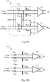
- Figs. 9A , 9B and 9C show an illustrative embodiment of a reconfigurable baseband unit including an amplifier implementation 900, an illustrative embodiment of the input noise 902 of the reconfigurable baseband unit, which includes a filter and an amplifier, and an illustrative embodiment of the voltage gain 908 of the reconfigurable baseband unit, respectively.
- line 904 represents the input noise in the complex receiver mode (LRR)
- line 906 represents the input noise in the real receiver mode (SRR).
- LRR complex receiver mode
- SRR real receiver mode
- the re-use of the high-pass filter capacitance of the Q-channel may result in a noise reduction of approximately 30 percent, while the voltage gain 908 and linearity are maintained.
- the switches may be designed in such a way that the isolation of the channels is not degraded.
- Fig. 10 shows an illustrative embodiment of a noise figure 100 of a receiver circuit of the kind set forth.
- line 1002 represents the noise figure in the complex receiver mode (LRR)
- line 1004 represents the noise figure in real receiver mode (SRR).
- LRR complex receiver mode
- SRR real receiver mode
- the application of the real receiver mode at lower frequencies results in a noise figure increase of approximately 3 dB compared to a scenario in which the receiver would keep operating in the complex receiver mode.
- the application of the complex receiver mode results in a better noise performance.
Landscapes
- Engineering & Computer Science (AREA)
- Radar, Positioning & Navigation (AREA)
- Remote Sensing (AREA)
- Physics & Mathematics (AREA)
- Computer Networks & Wireless Communication (AREA)
- General Physics & Mathematics (AREA)
- Electromagnetism (AREA)
- Radar Systems Or Details Thereof (AREA)
Priority Applications (3)
| Application Number | Priority Date | Filing Date | Title |
|---|---|---|---|
| EP20306155.1A EP3978948A1 (fr) | 2020-10-05 | 2020-10-05 | Unité radar et procédé de fonctionnement correspondant |
| US17/459,007 US12038528B2 (en) | 2020-10-05 | 2021-08-27 | Radar unit and corresponding operating method |
| CN202111139811.6A CN114384475A (zh) | 2020-10-05 | 2021-09-28 | 雷达单元和对应操作方法 |
Applications Claiming Priority (1)
| Application Number | Priority Date | Filing Date | Title |
|---|---|---|---|
| EP20306155.1A EP3978948A1 (fr) | 2020-10-05 | 2020-10-05 | Unité radar et procédé de fonctionnement correspondant |
Publications (1)
| Publication Number | Publication Date |
|---|---|
| EP3978948A1 true EP3978948A1 (fr) | 2022-04-06 |
Family
ID=72944084
Family Applications (1)
| Application Number | Title | Priority Date | Filing Date |
|---|---|---|---|
| EP20306155.1A Pending EP3978948A1 (fr) | 2020-10-05 | 2020-10-05 | Unité radar et procédé de fonctionnement correspondant |
Country Status (3)
| Country | Link |
|---|---|
| US (1) | US12038528B2 (fr) |
| EP (1) | EP3978948A1 (fr) |
| CN (1) | CN114384475A (fr) |
Cited By (1)
| Publication number | Priority date | Publication date | Assignee | Title |
|---|---|---|---|---|
| US12113571B2 (en) * | 2021-10-06 | 2024-10-08 | Nxp B.V. | Communication device and operating method |
Families Citing this family (2)
| Publication number | Priority date | Publication date | Assignee | Title |
|---|---|---|---|---|
| US20230100595A1 (en) * | 2021-09-24 | 2023-03-30 | Apple Inc. | Hybrid Radar with Reconfigurable Filters |
| US12021552B2 (en) * | 2021-12-30 | 2024-06-25 | Texas Instruments Incorporated | Intermediate frequency amplifier with a configurable high-pass filter |
Citations (2)
| Publication number | Priority date | Publication date | Assignee | Title |
|---|---|---|---|---|
| US20080287085A1 (en) * | 2007-05-14 | 2008-11-20 | Infineon Technologies Ag | RF front-end for a radar system |
| EP3376255A1 (fr) * | 2017-03-14 | 2018-09-19 | Nxp B.V. | Unité radar reconfigurable, circuit intégré et procédé associé |
Family Cites Families (6)
| Publication number | Priority date | Publication date | Assignee | Title |
|---|---|---|---|---|
| US5717403A (en) * | 1995-09-06 | 1998-02-10 | Litton Consulting Group, Inc. | Method and appartus for accurate frequency synthesis using global positioning system timing information |
| US6055556A (en) * | 1997-08-15 | 2000-04-25 | Motorola, Inc. | Apparatus and method for matrix multiplication |
| US7526052B2 (en) * | 2004-12-21 | 2009-04-28 | Raytheon Company | Configurable filter and receiver incorporating same |
| DE102008026698A1 (de) * | 2008-06-04 | 2009-12-17 | Fraunhofer-Gesellschaft zur Förderung der angewandten Forschung e.V. | Mehrfrequenzband-Empfänger |
| US8706071B2 (en) * | 2011-08-24 | 2014-04-22 | Aviacomm Inc. | Reconfigurable wideband receiver |
| US11460550B2 (en) * | 2017-09-19 | 2022-10-04 | Veoneer Us, Llc | Direct detection LiDAR system and method with synthetic doppler processing |
-
2020
- 2020-10-05 EP EP20306155.1A patent/EP3978948A1/fr active Pending
-
2021
- 2021-08-27 US US17/459,007 patent/US12038528B2/en active Active
- 2021-09-28 CN CN202111139811.6A patent/CN114384475A/zh active Pending
Patent Citations (2)
| Publication number | Priority date | Publication date | Assignee | Title |
|---|---|---|---|---|
| US20080287085A1 (en) * | 2007-05-14 | 2008-11-20 | Infineon Technologies Ag | RF front-end for a radar system |
| EP3376255A1 (fr) * | 2017-03-14 | 2018-09-19 | Nxp B.V. | Unité radar reconfigurable, circuit intégré et procédé associé |
Non-Patent Citations (1)
| Title |
|---|
| WU BOWEN ET AL: "A High-linearity CMOS Analog Baseband Circuit with reconfigurable Gain and Bandwidth for 76-81GHz Automotive Radar", 2018 14TH IEEE INTERNATIONAL CONFERENCE ON SOLID-STATE AND INTEGRATED CIRCUIT TECHNOLOGY (ICSICT), IEEE, 31 October 2018 (2018-10-31), pages 1 - 3, XP033464947, ISBN: 978-1-5386-4440-9, [retrieved on 20181205], DOI: 10.1109/ICSICT.2018.8565798 * |
Cited By (1)
| Publication number | Priority date | Publication date | Assignee | Title |
|---|---|---|---|---|
| US12113571B2 (en) * | 2021-10-06 | 2024-10-08 | Nxp B.V. | Communication device and operating method |
Also Published As
| Publication number | Publication date |
|---|---|
| CN114384475A (zh) | 2022-04-22 |
| US12038528B2 (en) | 2024-07-16 |
| US20220107388A1 (en) | 2022-04-07 |
Similar Documents
| Publication | Publication Date | Title |
|---|---|---|
| US12038528B2 (en) | Radar unit and corresponding operating method | |
| KR100314798B1 (ko) | 집적화된이미지제거믹서 | |
| US10587438B2 (en) | Method and system for controlling a modal antenna | |
| US8554267B2 (en) | Broadband input frequency adaptive technique for filter tuning and quadrature generation | |
| JP3413060B2 (ja) | 直接変換受信機 | |
| CN109154645B (zh) | Fmcw雷达中的动态iq失配校正 | |
| US10856225B2 (en) | Multi-band concurrent multi-channel receiver | |
| EP2047591B1 (fr) | Mélangeur de fréquences passif multifonction | |
| EP1315284A1 (fr) | Circuit transmetteur à conversion directe et circuit émetteur-récepteur intégré | |
| KR100612206B1 (ko) | 쿼드러처 신호를 이용한 레이더 시스템 | |
| CN213521865U (zh) | 一种变频接收系统 | |
| JP2009516475A (ja) | 設定可能なホモダイン/ヘテロダイン無線受信機及びそれを使用するrfid読取器 | |
| AU2016206585B2 (en) | Amplitude-noise reduction system and method for ultra-low phase-noise oscillators | |
| US8571143B2 (en) | Quadrature signal phase controller for controlling phase | |
| KR20010080269A (ko) | 주파수 안정화된 송/수신 회로 | |
| US7272187B2 (en) | Filter circuit and radio apparatus | |
| EP3771109B1 (fr) | Récepteur d'élimination d'image reconfigurable à large bande | |
| JPH104372A (ja) | 多モード無線電話 | |
| CN110764061B (zh) | 一种正交变频接收机 | |
| CN100505525C (zh) | 滤波电路 | |
| EP2242178A1 (fr) | Décalage de la phase numérique pour conférer un délai cible à un signal d'entrée pour générer un signal de sortie | |
| JP2012065200A (ja) | 送受信装置 | |
| US20250070734A1 (en) | Transimpedance Amplifier with Integrated Reconfigurable Filter | |
| WO2021146712A1 (fr) | Analyse de spectre à bande passante rapide | |
| KR100877870B1 (ko) | 신호 처리 장치 |
Legal Events
| Date | Code | Title | Description |
|---|---|---|---|
| PUAI | Public reference made under article 153(3) epc to a published international application that has entered the european phase |
Free format text: ORIGINAL CODE: 0009012 |
|
| STAA | Information on the status of an ep patent application or granted ep patent |
Free format text: STATUS: THE APPLICATION HAS BEEN PUBLISHED |
|
| AK | Designated contracting states |
Kind code of ref document: A1 Designated state(s): AL AT BE BG CH CY CZ DE DK EE ES FI FR GB GR HR HU IE IS IT LI LT LU LV MC MK MT NL NO PL PT RO RS SE SI SK SM TR |
|
| STAA | Information on the status of an ep patent application or granted ep patent |
Free format text: STATUS: REQUEST FOR EXAMINATION WAS MADE |
|
| 17P | Request for examination filed |
Effective date: 20221006 |
|
| RBV | Designated contracting states (corrected) |
Designated state(s): AL AT BE BG CH CY CZ DE DK EE ES FI FR GB GR HR HU IE IS IT LI LT LU LV MC MK MT NL NO PL PT RO RS SE SI SK SM TR |
|
| STAA | Information on the status of an ep patent application or granted ep patent |
Free format text: STATUS: EXAMINATION IS IN PROGRESS |
|
| 17Q | First examination report despatched |
Effective date: 20250204 |