EP3979235B1 - Lufteinlassdüse für gasheizgeräte - Google Patents
Lufteinlassdüse für gasheizgeräte Download PDFInfo
- Publication number
- EP3979235B1 EP3979235B1 EP21197407.6A EP21197407A EP3979235B1 EP 3979235 B1 EP3979235 B1 EP 3979235B1 EP 21197407 A EP21197407 A EP 21197407A EP 3979235 B1 EP3979235 B1 EP 3979235B1
- Authority
- EP
- European Patent Office
- Prior art keywords
- air inlet
- air
- inlet nozzle
- flow
- edge
- Prior art date
- Legal status (The legal status is an assumption and is not a legal conclusion. Google has not performed a legal analysis and makes no representation as to the accuracy of the status listed.)
- Active
Links
Images


Classifications
-
- G—PHYSICS
- G10—MUSICAL INSTRUMENTS; ACOUSTICS
- G10K—SOUND-PRODUCING DEVICES; METHODS OR DEVICES FOR PROTECTING AGAINST, OR FOR DAMPING, NOISE OR OTHER ACOUSTIC WAVES IN GENERAL; ACOUSTICS NOT OTHERWISE PROVIDED FOR
- G10K11/00—Methods or devices for transmitting, conducting or directing sound in general; Methods or devices for protecting against, or for damping, noise or other acoustic waves in general
- G10K11/16—Methods or devices for protecting against, or for damping, noise or other acoustic waves in general
- G10K11/161—Methods or devices for protecting against, or for damping, noise or other acoustic waves in general in systems with fluid flow
-
- F—MECHANICAL ENGINEERING; LIGHTING; HEATING; WEAPONS; BLASTING
- F23—COMBUSTION APPARATUS; COMBUSTION PROCESSES
- F23D—BURNERS
- F23D14/00—Burners for combustion of a gas, e.g. of a gas stored under pressure as a liquid
- F23D14/46—Details
-
- F—MECHANICAL ENGINEERING; LIGHTING; HEATING; WEAPONS; BLASTING
- F16—ENGINEERING ELEMENTS AND UNITS; GENERAL MEASURES FOR PRODUCING AND MAINTAINING EFFECTIVE FUNCTIONING OF MACHINES OR INSTALLATIONS; THERMAL INSULATION IN GENERAL
- F16L—PIPES; JOINTS OR FITTINGS FOR PIPES; SUPPORTS FOR PIPES, CABLES OR PROTECTIVE TUBING; MEANS FOR THERMAL INSULATION IN GENERAL
- F16L55/00—Devices or appurtenances for use in, or in connection with, pipes or pipe systems
- F16L55/02—Energy absorbers; Noise absorbers
- F16L55/033—Noise absorbers
-
- F—MECHANICAL ENGINEERING; LIGHTING; HEATING; WEAPONS; BLASTING
- F16—ENGINEERING ELEMENTS AND UNITS; GENERAL MEASURES FOR PRODUCING AND MAINTAINING EFFECTIVE FUNCTIONING OF MACHINES OR INSTALLATIONS; THERMAL INSULATION IN GENERAL
- F16L—PIPES; JOINTS OR FITTINGS FOR PIPES; SUPPORTS FOR PIPES, CABLES OR PROTECTIVE TUBING; MEANS FOR THERMAL INSULATION IN GENERAL
- F16L55/00—Devices or appurtenances for use in, or in connection with, pipes or pipe systems
- F16L55/02—Energy absorbers; Noise absorbers
- F16L55/033—Noise absorbers
- F16L55/0331—Noise absorbers by inserting an elongated element in the pipe
-
- F—MECHANICAL ENGINEERING; LIGHTING; HEATING; WEAPONS; BLASTING
- F24—HEATING; RANGES; VENTILATING
- F24H—FLUID HEATERS, e.g. WATER OR AIR HEATERS, HAVING HEAT-GENERATING MEANS, e.g. HEAT PUMPS, IN GENERAL
- F24H9/00—Details
- F24H9/0052—Details for air heaters
- F24H9/0057—Guiding means
- F24H9/0063—Guiding means in air channels
Definitions
- the invention relates to an air inlet nozzle for gas heaters and a gas heater equipped with the air inlet nozzle.
- the invention is used in particular for improved noise reduction during the supply of ambient air into the gas heater.
- a fan In gas heaters, such as the one in the DE 27 55 626 A1 , a fan is usually used to suck in ambient air in order to supply the combustion chamber of the gas heater with the oxygen required for combustion and to provide an ignitable gas-air mixture.
- a silencer is provided in front of the fan on the air intake side to reduce aerodynamic noise, with the air flow entering the silencer via an opening, often in the form of an inlet nozzle.
- Such an air inlet nozzle can be formed with a pipe section and a round disk made of any material.
- the disk has a peripheral edge with a smooth surface and a centrally arranged round air inlet opening with a sharp edge, so that depending on the incoming air volume flow, flow separations can occur at the edge, which can generate noise emissions.
- flow-induced vibration excitation can also occur at the silencer due to its low weight, which radiates additional secondary airborne sound, so that the noise level can increase further, especially at certain operating points.
- an air inlet nozzle for a gas heater which comprises a hollow body with at least one air inlet opening, wherein the air inlet opening is surrounded by an opening edge partially covering the hollow body, and wherein the opening edge is designed with several exposed flow influencing elements.
- the air inlet nozzle is advantageously designed or configured for a silencer, in particular an air silencer, to reduce aerodynamic noise and/or avoid additional aerodynamic noise.
- the air inlet nozzle can be arranged or installed with the silencer on the air supply path of a gas heater, in particular a gas heater for buildings.
- a building gas heater in particular can be installed directly in an interior space where a particularly low noise level (e.g. less than 50 dB at night) is required.
- a particularly low noise level e.g. less than 50 dB at night
- the air inlet nozzle can also be used with the interacting silencer in the air supply path of any other embodiment of a gas heater.
- the hollow body can be designed in particular in the manner of a pipe section (possibly with a locally enlarged cross-section).
- the hollow body or its wall therefore limits a cavity in which the incoming air can be distributed. It is possible that structures, guard rails, bodies, etc. are incorporated in the cavity, which set a (multiple) division and/or redirection of the air flow within the hollow body.
- the hollow body can be designed with a single air inlet opening. It is possible for the air inlet opening or each individual air inlet opening to have an opening edge.
- the mouth edge is arranged in the inflow area of the hollow body and in the form of a disk in front of or on the hollow body. Depending on the design, it covers the hollow body at least partially, thus in particular forming a reduced or tapered cross-section of the air inflow opening compared to the cross-section (both viewed in the flow direction of the incoming air flow) of the hollow body.
- the mouth edge can be designed in the manner of an undercut for the air flow.
- the mouth edge is a disk that has an inner, closed edge that is designed to form the air inflow opening.
- the mouth edge can be connected to the wall of the hollow body so that the mouth edge partially covers the hollow body with a preferably central air inflow opening and the air flow can enter the hollow body via the air inflow opening.
- the mouth edge is usually made of a material with a predetermined material thickness. Therefore, the air inflow opening cannot practically be viewed in purely 2-dimensional terms. Rather, the air inlet opening or edge can be assigned a depth (extension in the direction of flow), which can also be referred to as the air inlet opening depth.
- the exposed flow influencing elements are used in particular for the targeted adjustment, reduction and/or prevention of air separation when the air flow flows into the hollow body via the air inlet nozzle.
- "exposed” is intended to express in particular that these elements have significantly protruding sections, elevations, etc. that are deliberately created starting from a (base) surface of the mouth edge, which in particular does not mean “pure” roughness fluctuations of the surface. It is possible, for example, that these exposed elements are designed with a raised edge and a lowered center or with an edge close to the (base) surface and a raised center.
- These flow-influencing elements can be exposed at least partially in or against the (incoming) air flow and/or obliquely or perpendicularly to it. It is possible that the flow-influencing elements extend practically exclusively into the air inlet opening delimited by the mouth edge. It is possible that the flow-influencing elements do not extend into the hollow body or cavity located behind the air inlet opening in the flow direction.
- Air separation is the phenomenon of vortices forming in the air on the flow body. If the vortices are formed in an undesirable manner, they can cause additional sound emissions, which has a negative impact on noise reduction. This is because airborne sound is essentially a mechanical vibration in the air that can also be transmitted to the solid body, so that flow-induced vibrations can be generated in the solid body such as in the edge, in the wall of the air supply duct and in the silencer. This is referred to here as undesirable flow separation.
- the air flow should, if possible, flow towards or through the silencer in a predetermined form and/or in a predetermined direction in order to reduce the noise as much as possible.
- the majority or even a multitude of flow influencing elements can have the same or different shapes, be similar in orientation, arranged at an angle to one another and/or opposite one another, be the same and/or different in size and dimension, and be designed as one piece with one another and/or separately from one another. They can usually be arranged next to and/or in the air inlet opening or locally on the mouth edge. In particular, they lead to better mixing of air flows with different speeds, so that undesirable flow separation, i.e. the formation of air turbulence in undesirable places or in undesirable directions, is reduced or even prevented. The air flow is thus directed in the desired direction, which can reduce noise.
- the exposed flow influencing elements are arranged adjacent to one another.
- they can be directly adjacent to one another, (partially) merge into one another and/or form a distance from one another.
- the exposed flow influencing elements extend locally into the air inlet opening.
- local is meant in particular that an individual flow influencing element extends only over a partial area of the circumference of the air inlet opening, wherein the partial area preferably comprises less than 20%, in particular a maximum of 15% or even only a maximum of 5% of the circumference. It is possible for a flow influencing element to be aligned parallel and/or obliquely to the cross section of the air inlet opening. It is preferred that all flow influencing elements protruding into the air inlet opening are shaped in the same way but are arranged offset from one another in the direction of the circumference of the air inlet opening.
- the exposed flow influencing elements extend into the air inlet opening such that they are arranged directly on the edge surface and/or along the edge circumference at the edge, and may extend into the air inlet opening such that they are arranged along the edge depth at the edge.
- the notches described above can be arranged not only on the mouth edge surface in plan view, but also on the edge surface along the edge depth, so that the notches are distributed starting from the mouth edge surface into the air inlet opening.
- the exposed flow influencing elements can also be designed in the form of baffles which, in plan view, are arranged along the air inflow circumference and extend into the air inflow opening or limit it (partially or completely).
- At least one of the exposed flow influencing elements has an impact surface (for the air flow) with a maximum width of at least 5% of the air inlet opening circumference.
- the geometry of the impact surface should not be limited to a specific shape.
- the base of the impact surface can be arranged directly on the edge and the head of the impact surface can extend into the air inlet opening in plan view.
- the maximum width of the impact surface is preferably 5 to 10% of the air inlet opening circumference, with 6 to 8 impact surfaces being particularly preferably installed around the air inlet opening.
- the impact surface can lead to better mixing of air flows of different speeds, which ultimately at least partially prevents undesirable flow separation and thus reduces noise emissions.
- the impact surface can be formed, for example, as an isosceles triangle, with its base or foot positioned directly on the edge and the angle between the two equally long opposite sides of the legs as the head directed towards the center of the air inlet opening. There can be 5 to 8 such impact surfaces directly next to each other, so that the sides of the legs form a chevron-shaped air inlet opening in plan view.
- the triangles preferably all have the same height, which is preferably less than half the maximum width of the air inlet opening.
- the impact surfaces can also be formed in pieces as part of the mouth edge.
- the exposed flow influencing elements extend locally at least partially perpendicular to the air inlet opening.
- the exposed flow influencing elements can, for example, be designed in the form of notches that are regularly arranged next to one another, so that vertically protruding dents or elevations are formed between the adjacent notches on the surface of the mouth edge.
- a turbulent boundary layer has the advantage that the rest of the air is hardly affected by the boundary layer.
- the rest of the air flows past the turbulent boundary layer undisturbed, even less so than on a conventional smooth surface of the mouth edge. This can reduce noise.
- the notches are preferably arranged next to one another in such a way that the surface of the mouth edge looks like the surface of a golf ball.
- the exposed flow influencing elements can also be designed in the form of projections, for example, which are placed next to each other on the surface of the mouth edge.
- the projections essentially act in a similar way to the dents formed by notches and ensure that many small vortices form in the boundary layer.
- Such a turbulent boundary layer influences the rest of the air flow much less than a laminar boundary layer, as described above for the notches.
- the projections can, for example, be angular and can be arranged evenly and/or radially distributed around the air inlet opening directly at the edge and/or adjacent to it on the (flow-exposed) surface of the mouth edge.
- a (radially extending) length of the projections is preferably 50% to 70% of the width of the mouth edge, the width being the difference in radius from the edge/air inlet opening to the radially outer boundary.
- a (extending in the circumferential direction of the air inlet opening) width of the projections is preferably 3% to 10%, in particular 4% ( ⁇ 1/24) of the circumference of the edge.
- the pitch angle between two adjacent projections is preferably 45 degrees, so that a total of eight projections are provided around the air inlet opening.
- the exposed flow influencing elements in the form of notches arranged on the mouth edge surface can extend perpendicular to the air inlet opening in the sectional view.
- the exposed flow-influencing elements can also be distributed densely and continuously in the form of slats along the air inlet opening at the edge and extend perpendicular to the air inlet opening in the sectional view.
- a slat In comparison with the impact surface, a slat has a much smaller width.
- the densely and continuously distributed slats therefore act like a combed extension of the edge in the direction of air flow.
- the slats can effectively break up the turbulence balls into smaller turbulence balls, thus reducing the intensity of air pressure fluctuations, which leads to reduced noise emissions.
- At least one of the exposed flow influencing elements has a lamella extending at least partially along the air inflow opening with a length of at least 50% of the air inflow opening depth.
- a single type of the exposed flow influencing elements proposed here can be provided in the air inlet nozzle. However, it is also possible for several or a large number of the types of the exposed flow influencing elements proposed here to be provided in the air inlet nozzle.
- exposed flow influencing elements are formed with a regular surface structure or form such a structure.
- the exposed flow-influencing elements can be formed, for example, as notches with a hemispherical surface structure or as projections with a cuboid-shaped surface structure or as impact surfaces with a triangular surface structure or as lamellae with a prong-shaped surface structure.
- regular means in particular that the exposed flow-influencing elements are arranged in a similar manner and adjacent to one another, so that a consistent pattern is provided which forms the flat surface structure.
- the mouth edge is neither smooth nor forms a round air inlet opening. In other words, this does not include air inlet nozzles that form a straight collar whose surface profile is only characterized by surface roughness.
- the mouth edge is a separate component that is arranged on an at least partially cylindrical hollow body. It is possible for the mouth edge to partially enclose the hollow body and be connected to it (in a material-locking and/or force-locking manner).
- the exposed flow influencing elements are micro-turbulence generators.
- the flow influencing elements serve to prevent flow separation in undesirable forms by creating a turbulent boundary layer in the form of notches or projections on the mouth edge surface or by breaking up the undesirable turbulence balls into smaller turbulence balls in the form of impact surfaces or lamellae.
- the flow influencing elements are therefore essentially micro-turbulence generators.
- a gas heater comprises an air inlet nozzle as described above. It is also preferred if a silencer is arranged behind the air inlet nozzle on the air supply path to the combustion chamber of the gas heater.
- the air inlet nozzle can divert the air flow through the air flow deflector so that the air flow can follow the contour of the air inlet nozzle as far as possible and so the undesirable flow separations can be avoided. It is particularly advantageous to use the air inlet nozzle according to the invention in front of the air silencer and to work together with the air silencer for optimized aerodynamic noise reduction.
- the table shows that the loudness of the air inlet nozzles with exposed flow influencing elements in four exemplary embodiments is lower than the loudness of a conventional air inlet nozzle without flow influencing elements.
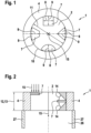
- Fig.1 shows impact surfaces 7 with different geometric shapes, namely a triangular, a rectangular, a trapezoidal and a semi-circular geometric shape, which extend from a disk-shaped mouth edge 4 into the air inlet opening 2.
- the geometry of the impact surface 7 does not necessarily have to be limited to a specific shape.
- the impact surface width 8, which corresponds to the maximum Width of the impact surface corresponds to at least 5%, preferably 5% to 10%, of the air inflow circumference 10 and the impact surface height 9 is a maximum of 50%, preferably 20% to 30%, of the air inflow opening width 11.
- several impact surfaces 7 can be arranged next to one another to form a non-circular air inflow opening 2.
- eight triangular impact surfaces 7 can be arranged seamlessly next to one another so that the air inflow opening 2 is designed as a chevron (cf. Fig.5 ) is designed.
- Fig.2 shows a vertical sectional view of an air inlet nozzle 1, with a trapezoidal impact surface 7 that can be flowed onto being indicated on the left and a triangular impact surface 7 that can be flowed onto the right.
- the mouth edge 4 has a thickness 13 in the sectional view, which forms an air inflow opening depth 12.
- the impact surfaces 7 can be arranged at different heights in relation to the air inflow depth 12 or at the same height relative to the air inflow opening 12. It is possible for the impact surface 7, as indicated on the right, to be attached at a first angle 14 inclined to the air inflow opening 2 or inflow direction 15, whereby this angle can be adjustable (possibly independently during operation depending on the flow).
- the angle 14 is preferably a maximum of 30°.
- the mouth edge 4 is connected to the hollow body wall 27 and covers the hollow body 26 so that the air flow can flow into the hollow body 26 via the air inlet opening 2.
- Fig.3 shows slats 16 in a cuboid or conical geometry, which are distributed densely and continuously along the air inlet opening 2 at the edge 3 or along the circumference 18 and thus form a kind of edge comb.
- the slats 16 can be designed to run radially or at a second angle 17 obliquely to the radius. In comparison with the impact surfaces 7 in Fig.1 the slats 16 essentially have a much smaller dimension.
- Fig.4 shows a vertical sectional view of an opening edge 4.
- the slats 16 can extend, for example, in relation to the air inlet opening depth 12 at different heights and aligned essentially perpendicular to the air inlet opening 2.
- the slat length 20 is preferably at least 50% of the air inlet opening depth 12.
- the slats 16 can extend over their slat length 20 to different distances into the air inlet opening 2, as shown on the right in Fig.4 indicated, whereby the protruding lamella contour 19 can also be designed non-linearly.
- Fig.5 shows above, by way of example and schematically, air inlet nozzles 1 in four different embodiments A, B, C, D and below their associated noise level measurements in a diagram 21.
- the embodiment A has eight triangular baffles 7, which are arranged as flow influencing elements along the circumference of the air inflow opening 2 and extend into the air inflow opening 2, so that the air flow opening 2 is designed as a chevron.
- the embodiment B has a plurality of slats 16 which are arranged as flow influencing elements densely and continuously along the circumference of the air inflow opening 2 and extend perpendicular to the air inflow opening 2, so that an edge comb is formed which can be flowed behind.
- the embodiment C has a mouth edge 4 which surrounds the air inflow opening 2, wherein the surface of the mouth edge 4 has eight square projections 6 as flow influencing elements, wherein the projections 6 are distributed evenly and radially around the air inflow opening 2.
- the embodiment D has a mouth edge 4 which surrounds the air inlet opening 2, wherein the surface of the mouth edge 4 has many small and regularly arranged notches 5 as flow influencing elements, similar to a golf ball surface.
- the diagram 21 shows the measured noise levels 22 in relation to the frequencies 23.
- the different frequencies 23 represent the different operating points.
- the solid characteristic curve R shows the measured noise levels 22 for a conventional air inlet nozzle
- the dotted lines A, B, C, D show the measured noise levels 22 for the air inlet nozzle in the embodiments A, B, C, D.
- the noise levels 22 of the embodiments A, B, C, D are significantly lower than the noise levels 22 of the conventional embodiment.
- the air inlet nozzles with the flow influencing elements can reduce noise significantly better than the conventional air inlet nozzle in the frequency range 1 to approx. 16 KHz, whereby this frequency range also includes the most sensitive range (3 to 4 KHz) of the human sense of hearing.
- Fig.6 shows a schematic representation of a gas heater 28 equipped with the air inlet nozzle 1 described above.
- the air inlet nozzle 1 is arranged in front of a silencer 29 on the air supply path 25 to the combustion chamber 30 of the gas heater 28.
- the air flow flows via the air inlet nozzle 1 into the hollow body 26 and then via the silencer 29 into the combustion chamber 30.
- the flow influencing elements not in Figure 6 shown
- the formation of undesirable vortices is avoided. This means that flow-induced vibration excitation at the silencer 29 can be avoided, which means that noise can be effectively reduced.
Landscapes
- Engineering & Computer Science (AREA)
- Chemical & Material Sciences (AREA)
- Combustion & Propulsion (AREA)
- Physics & Mathematics (AREA)
- Mechanical Engineering (AREA)
- General Engineering & Computer Science (AREA)
- Aviation & Aerospace Engineering (AREA)
- Fluid Mechanics (AREA)
- Acoustics & Sound (AREA)
- Multimedia (AREA)
- Duct Arrangements (AREA)
- Air-Conditioning For Vehicles (AREA)
Description
- Die Erfindung betrifft eine Lufteinlassdüse für Gasheizgeräte und ein mit der Lufteinlassdüse ausgestattetes Gasheizgerät. Die Erfindung kommt insbesondere zur verbesserten Geräuschreduktion während der Zufuhr von Umgebungsluft in das Gasheizgerät zur Anwendung.
- In Gasheizgeräten, wie zum Beispiel in dem der
DE 27 55 626 A1 , wird in der Regel ein Gebläse zum Ansaugen von Umgebungsluft eingesetzt, um die Brennkammer des Gasheizgerätes mit dem für die Verbrennung notwendigen Sauerstoff zu versorgen und ein zündfähiges Gas-Luft-Gemisch bereitzustellen. In den meisten Fällen ist vor dem Gebläse luftsaugseitig ein Schalldämpfer zur Reduktion von aerodynamischen Geräuschen vorgesehen, wobei die Luftströmung über eine Öffnung, oftmals in Form einer Einlassdüse, in den Schalldämpfer eintritt. - Eine solche Lufteinlassdüse kann mit einem Rohrabschnitt und einer runden Scheibe aus beliebigem Material gebildet sein. Die Scheibe weist einen umlaufenden Rand mit glatter Oberfläche und eine mittig angeordnete runde Lufteinströmungsöffnung mit einer scharfen Kante auf, sodass in Abhängigkeit vom eintretenden Luftvolumenstrom an der Kante Strömungsablösungen entstehen können, welche Geräuschemission erzeugen können. Abhängig von der Ausprägung dieser Strömungsablösungen kann zudem am Schalldämpfer ggf. aufgrund seines geringen Gewichtes eine strömungsinduzierte Schwingungsanregung auftreten, die zusätzlichen sekundären Luftschall abstrahlt, sodass der Geräuschpegel, insbesondere bei bestimmten Betriebspunkten, weiter ansteigen kann.
- Es ist daher Aufgabe der Erfindung, die mit Bezug auf den Stand der Technik geschilderten Problem wenigstens teilweise zu lindern und insbesondere eine neuartige Lufteinlassdüse mit einer Geometrie bzw. Kontur bereitzustellen, die sich für den Einsatz luftsaugseitig vor dem Gebläse angebrachten Schalldämpfer eines Gasheizgerätes eignet.
- Diese Aufgabe wird gemäß den Merkmalen des Anspruchs 1 gelöst. Vorteilhafte Ausgestaltungen ergeben sich aus den Merkmalen der abhängigen Ansprüche. Es ist darauf hinzuweisen, dass die Merkmale der Ansprüche mit weiteren Merkmalen der Beschreibung und/oder der Figuren kombinierbar sind, wodurch weitere Ausführungsvarianten aufgezeigt sind.
- Hierzu trägt eine Lufteinlassdüse für ein Gasheizgerät bei, die einen Hohlkörper mit mindestens einer Lufteinströmungsöffnung umfasst, wobei die Lufteinströmungsöffnung von einem den Hohlkörper teilweise überdeckenden Mündungsrand umgeben ist, und wobei der Mündungsrand mit mehreren exponierten Strömungsbeeinflusselementen ausgeführt ist.
- Die Lufteinlassdüse ist vorteilhafter Weise für einen Schalldämpfer, insbesondere einen Luftschalldämpfer, zur Reduktion von aerodynamischen Geräuschen und/oder Vermeidung von zusätzlichen aerodynamischen Geräuschen eingerichtet bzw. ausgelegt. Die Lufteinlassdüse kann mit dem Schalldämpfer auf dem Luftzufuhrweg eines Gasheizgerätes, insbesondere eines Gasheizgerätes für Gebäude, angeordnet oder installiert sein. Gerade ein Gebäude-Gasheizgerät kann direkt in einem Innenraum angebracht sein, wo ein besonders niedriger Geräuschpegel (z. B. kleiner als 50 dB in der Nacht) verlangt wird. Grundsätzlich kann die Lufteinlassdüse aber auch mit dem zusammenwirkenden Schalldämpfer im Luftzufuhrweg jeder anderen Ausführungsform eines Gasheizgerätes eingesetzt werden.
- Der Hohlkörper kann insbesondere nach Art eines (ggf. lokal querschnittserweiterten) Leitungsabschnitt ausgeführt sein. Der Hohlkörper bzw. dessen Wandung begrenzt daher einen Hohlraum, in dem die einströmende Luft sich verteilen kann. Es ist möglich, dass im dem Hohlraum Strukturen, Leitplanken, Körper, etc. aufgenommen sind, die eine (vielfache) Aufteilung und/oder Umlenkung der Luftströmung innerhalb des Hohlkörpers einstellen.
- Der Hohlkörper kann mit einer einzelnen Lufteinströmungsöffnung ausgeführt sein. Es ist möglich, dass die Lufteinströmungsöffnung bzw. jede einzelne Lufteinströmungsöffnung einen Mündungsrand aufweist.
- Der Mündungsrand ist im Einströmungsbereich des Hohlkörpers und in Form einer Scheibe vor bzw. an dem Hohlkörper angeordnet sein. Er überdeckt den Hohlkörper je nach Gestaltung zumindest teilweise, bildet also insbesondere einen reduzierten oder verjüngten Querschnitt der Lufteinströmungsöffnung gegenüber dem Querschnitt (beides betrachtet in Strömungsrichtung der eintretenden Luftströmung) des Hohlkörpers aus. Der Mündungsrand kann nach Art eines Hinterschnitts für die Luftströmung ausgebildet sein. Der Mündungsrand ist eine Scheibe, die eine innenliegende, geschlossene Kante hat, welche zur Bildung der Lufteinströmungsöffnung ausgeführt ist. Der Mündungsrand kann mit der Wandung des Hohlkörpers verbunden sein, sodass der Mündungsrand mit einer bevorzugt mittigen Lufteinströmungsöffnung den Hohlkörper teilweise überdeckt und die Luftströmung über die Lufteinströmungsöffnung in den Hohlkörper eintreten kann. Der Mündungsrand ist zumeist aus einem Material mit einer vorgegebenen Materialstärke gebildet. Daher ist die Lufteinströmungsöffnung praktisch nicht rein 2-dimensional zu betrachten. Vielmehr kann folglich der Lufteinströmungsöffnung bzw. Kante eine Tiefe (Erstreckung in Strömungsrichtung) zugeordnet werden, die auch als Lufteinströmungsöffnungstiefe bezeichnet werden kann.
- Die exponierten Strömungsbeeinflusselemente dienen hierbei insbesondere zur gezielten Einstellung, Reduzierung und/oder Vermeidung von Luftablösungen, wenn die Luftströmung über die Lufteinlassdüse in den Hohlkörper fließt. "Exponiert" soll in diesem Zusammenhang insbesondere zum Ausdruck bringen, dass diese Elemente ausgehend von einer (Grund-)Fläche des Mündungsrandes gezielt erzeugte signifikant hervorstehende Abschnitte, Erhebungen, etc. aufweisen, worunter insbesondere keine "reinen" Rauheitsschwankungen der Fläche zu verstehen sind. Es ist beispielsweise möglich, dass diese exponierten Elemente mit einem erhöhten Rand und einem erniedrigten Zentrum oder mit einem der (Grund-)Fläche nahen Rand und einem erhöhten Zentrum ausgebildet sind. Diese Strömungsbeeinflusselemente können zumindest teilweise in bzw. entgegen der (ankommenden) Luftströmung und/oder schräg bzw. senkrecht dazu exponiert sein. Es ist möglich, dass sich die Strömungsbeeinflusselemente praktisch ausschließlich in die vom Mündungsrand begrenzte Lufteinströmungsöffnung erstrecken. Es ist möglich, dass sich die Strömungsbeeinflusselemente nicht in den in Strömungsrichtung hinter der Lufteinströmungsöffnung befindlichen Hohlkörper bzw. Hohlraum hinein erstrecken.
- Unter Luftablösungen versteht man das Phänomen der Wirbelbildung in der Luft am Strömungskörper. Wenn die Wirbel in unerwünschter Ausprägung ausgebildet sind, können sie zusätzliche Schallemission verursachen, was die Geräuschreduktion negativ beeinträchtigt. Denn der Luftschall ist im Wesentlichen eine mechanische Schwingung in der Luft, die auch in den Festköper übertragen werden kann, sodass strömungsinduzierte Schwingungen in den Festköper wie in der Kante, in der Wandung des Luftzufuhrkanales und im Schalldämpfer erzeugt werden können. Dies wird hier als unerwünschte Strömungsablösungen bezeichnet.
- Daher soll die Luftströmung möglichst nach dem Einströmen über die Lufteinströmungsöffnung in einer vorgegebenen Ausprägung und/oder in eine vorgegebene Richtung den Schalldämpfer anströmen bzw. durchströmen, um die Geräusche so weit wie möglich zu reduzieren.
- Die Mehrzahl oder gar Vielzahl von Strömungsbeeinflusselementen können gleiche oder ungleiche Formen aufweisen, in der Orientierung einander gleichartig, schräg zueinander und/oder entgegengesetzt angeordnet, hinsichtlich ihrer Größe und Dimension gleich und/oder abweichend ausgeführt sowie einteilig miteinander und/oder getrennt voneinander ausgebildet sein. Sie können regelmäßig neben und/oder in der Lufteinströmungsöffnung bzw. lokal am Mündungsrand angeordnet sein. Sie führen insbesondere zu einer besseren Vermischung von Luftströmungen mit unterschiedlichen Geschwindigkeiten, sodass die unerwünschten Strömungsablösungen, d. h. die Entstehung von Luftverwirbelungen an unerwünschten Stellen bzw. in unerwünschte Richtungen, reduziert oder gar verhindert werden. Die Luftströmung wird somit in die gewünschte Richtung geleitet, wodurch die Geräusche reduziert werden können.
- Es ist bevorzugt, wenn die exponierten Strömungsbeeinflusselemente benachbart zueinander angeordnet sind. Hierfür können diese unmittelbar aneinandergrenzen, (teilweise) ineinander übergehen und/oder eine Distanz zueinander ausbilden.
- Es ist bevorzugt, wenn die exponierten Strömungsbeeinflusselemente sich lokal in die Lufteinströmungsöffnung hinein erstrecken. Mit "lokal" ist insbesondere gemeint, dass ein einzelnes Strömungsbeeinflusselement sich nur über einen Teilbereich des Umfangs der Lufteinströmungsöffnung erstreckt, wobei der Teilbereich bevorzugt kleiner 20 %, insbesondere maximal 15 % oder sogar nur maximal 5 % des Umfangs umfasst. Es ist möglich, dass ein Strömungsbeeinflusselement parallel und/oder schräg zum Querschnitt der Lufteinströmungsöffnung ausgerichtet ist. Bevorzugt ist, dass alle sich in die Lufteinströmungsöffnung hineinragenden Strömungsbeeinflusselemente in gleicher Weise geformt aber in Richtung des Umgangs der Lufteinströmungsöffnung versetzt zueinander angeordnet sind.
- Die exponierten Strömungsbeeinflusselemente erstrecken sich so in die Lufteinströmungsöffnung, dass sie unmittelbar auf der Kantenober-fläche und/oder entlang des Kantenumfangs an der Kante angeordnet sind, und können sich so in die Lufteinströmungsöffnung erstrecken, dass sie entlang der Kantentiefe an der Kante angeordnet sind.
- Hierbei können beispielweise die oben beschriebenen Einkerbungen nicht nur in der Draufsicht auf der Mündungsrandoberfläche, sondern auch auf der Kantenoberfläche entlang der Kantentiefe angeordnet sein, sodass sich die Einkerbungen ausgehend von der Mündungsrandoberfläche in die Lufteinströmungsöffnung verteilen.
- Darüber hinaus können die exponierten Strömungsbeeinflusselemente auch in Form von Prallflächen ausgeführt sein, die in der Draufsicht entlang dem Lufteinströmungsumfang angeordnet sind und sich in die Lufteinströmungsöffnung hinein erstrecken bzw. diese (teilweise oder vollständig) begrenzen.
- Es ist bevorzugt, wenn mindestens eines der exponierten Strömungsbeeinflusselemente eine Prallfläche (für die Luftströmung) mit einer maximalen Breite von mindestens 5 % des Lufteinströmungsöffnungsumfangs aufweist.
- Die Geometrie der Prallfläche soll grundsätzlich nicht auf eine bestimmte Form beschränkt sein. Dabei kann der Fuß der Prallfläche unmittelbar an der Kante angeordnet sein und sich der Kopf der Prallfläche in der Draufsicht in die Lufteinströmungsöffnung erstrecken. Die maximale Breite der Prallfläche beträgt vorzugsweise 5 bis 10% des Lufteinströmungsöffnungsumfangs, wobei besonders bevorzugt 6 bis 8 Prallflächen um der Lufteinströmungsöffnung angebracht werden können. Die Prallfläche kann zu einer besseren Vermischung von verschieden schnellen Luftströmungen führen, was schließlich die unerwünschte Strömungsablösung zumindest teilweise unterbindet und somit eine Reduktion der Geräuschemission bewirkt.
- Die Prallfläche kann beispielweise als gleichschenkliges Dreieck ausgeformt werden, wobei dessen Basis oder Fuß unmittelbar an der Kante angeordnet und der Winkel zwischen den zwei gleich langen gegenüberliegenden Schenkelseiten als Kopf zur Mitte der Lufteinströmungsöffnung hin ausgerichtet ist. Es können 5 bis 8 Stück derartige Prallflächen unmittelbar nebeneinander liegen, somit bilden die Schenkelseiten in der Draufsicht eine chevronförmige Lufteinströmungsöffnung aus. Die Dreiecke besitzen vorzugsweise alle die gleiche Höhe, die vorzugsweise kleiner als die Hälfte der maximalen Lufteinströmungsöffnungsbreite ist. Die Prallflächen können auch als Bestandteil des Mündungsrandes stückig ausgeformt werden.
- Es ist bevorzugt, wenn sich die exponierten Strömungsbeeinflusselemente lokal zumindest teilweise senkrecht zur Lufteinströmungsöffnung erstrecken.
- Die exponierten Strömungsbeeinflusselemente können beispielweise in Form von Einkerbungen ausgeführt sein, die regelmäßig nebeneinander liegen, sodass senkrecht hervorstehende Dellen bzw. Erhebungen zwischen den nebeneinander liegenden Einkerbungen auf der Oberfläche des Mündungsrandes ausgebildet werden. Wenn die Luft an den Dellen vorbei strömt, werden viele kleine Wirbel an den Dellen ausgebildet, sodass eine turbulente Grenzschicht an der Oberfläche ausgebildet werden kann. Eine solche turbulente Grenzschicht hat den Vorteil, dass die restliche Luft von der Grenzschicht kaum beeinflusst wird. Die restliche Luft strömt an der turbulenten Grenzschicht ungestört vorbei, und zwar noch ungestörter als an einer herkömmlichen glatten Oberfläche des Mündungsrandes. Somit können die Geräusche reduziert werden. Die Einkerbungen liegen vorzugsweise derart nebeneinander, dass die Oberfläche des Mündungsrandes wie eine Golfballoberfläche aussieht.
- Anstatt der Einkerbungen können die exponierten Strömungsbeeinflusselemente beispielweise auch in Form von Vorsprüngen ausgeführt werden, die nebeneinander auf der Oberfläche des Mündungsrandes angeordnet sind. Dabei wirken die Vorsprünge im Wesentlichen ähnlich wie die von Einkerbungen ausgebildeten Dellen und sorgen dafür, dass sich in der Grenzschicht viele kleine Wirbel ausbilden. Eine solche turbulente Grenzschicht beeinflusst die übrige Luftströmung viel weniger als eine laminare Grenzschicht, wie es oben bei den Einkerbungen beschrieben wird.
- Die Vorsprünge können beispielweise eckig ausgeführt sein und um die Lufteinströmungsöffnung unmittelbar an der Kante und/oder benachbart auf der (angeströmten) Oberfläche des Mündungsrandes gleichmäßig und/oder radial verteilt angeordnet sein.
- Eine (sich radial erstreckende) Länge der Vorsprünge beträgt vorzugsweise 50% bis 70% der Breite des Mündungsrandes, wobei die Breite die Radiendifferenz von Kante / Lufteintrittsöffnung zur radial äußeren Grenze ist. Eine (sich in Umfangsrichtung der Lufteinlass-öffnung erstreckende) Breite der Vorsprünge beträgt bevorzugt 3% bis 10%, insbesondere 4% (≈ 1/24) des Umfanges der Kante. Der Teilungswinkel zwischen zwei benachbarten Vorsprüngen beträgt vorzugsweise 45 Grad, sodass insgesamt acht Vorsprünge rund um die Lufteinströmungsöffnung vorgesehen sind.
- Hierbei können sich die exponierten Strömungsbeeinflusselemente in Form der Einkerbungen, die auf der Mündungsrandoberfläche angeordnet sind, in der Schnittansicht senkrecht zur Lufteinströmungsöffnung erstrecken.
- Hierbei können sich die exponierten Strömungsbeeinflusselemente auch in Form von Lamellen dicht und kontinuierlich entlang der Lufteinströmungsöffnung an der Kante verteilen und in der Schnittansicht senkrecht zur Lufteinströmungsöffnung erstrecken. Im Vergleich mit der Prallfläche weist eine Lamelle eine viel kleinere Breite auf. So wirken die dicht und kontinuierlich verteilten Lamellen wie eine gekämmte Verlängerung der Kante in die Luftströmungsrichtung. An den Lamellen können die Turbulenzballen wirkungsvoll in kleinere Turbulenzballen aufgebrochen werden, somit wird die Stärke von Luftdruckschwankungen reduziert, was zu einer verminderten Geräuschemission führt.
- Es ist bevorzugt, wenn mindestens eines der exponierten Strömungsbeeinflusselemente eine sich zumindest teilweise entlang der Lufteinströmungsöffnung verlaufende Lamelle mit einer Länge von mindestens 50 % der Lufteinströmungsöffnungstiefe aufweist.
- Es können bei der Lufteinlassdüse eine einzelne Art der hier vorgeschlagenen exponierten Strömungsbeeinflusselemente vorgesehen sein. Es ist jedoch auch möglich, dass bei der Lufteinlassdüse mehrere oder eine Vielzahl der Arten der hier vorgeschlagenen exponierten Strömungsbeeinflusselemente vorgesehen sind.
- Es ist bevorzugt, wenn exponierte Strömungsbeeinflusselemente mit einer regelmäßigen Oberflächenstruktur gebildet sind bzw. eine solche ausbilden.
- Die exponierten Strömungsbeeinflusselemente können beispielweise als Einkerbungen mit einer halbkugelförmigen Oberflächenstruktur oder als Vorsprünge mit einer quaderförmigen Oberflächenstruktur oder als Prallflächen mit einer dreieckförmigen Oberflächenstruktur oder als Lamellen mit einer zinkenförmigen Oberflächenstruktur ausgeformt werden. Regelmäßig bedeutet in diesem Zusammenhang insbesondere, dass die exponierten Strömungsbeeinflusselemente gleichartig und benachbart zueinander angeordnet sind, so dass ein gleichbleibendes Muster gegeben ist, welche die flächige Oberflächenstruktur bildet.
- Es ist bevorzugt, wenn der Mündungsrand weder glatt ist noch eine runde Lufteinströmungsöffnung bildet. Mit anderen Worten sollen insbesondere keine Lufteinlassdüsen gemeint sein, die einen geradlinigen Kragen ausbilden, deren Oberflächenprofil nur von einer Oberflächenrauigkeit geprägt ist.
- Es ist bevorzugt, wenn der Mündungsrand ein separates Bauteil ist, dass an einem zumindest teilweise zylindrischen Hohlkörper angeordnet ist. Es ist möglich, dass der Mündungsrand teilweise den Hohlkörper einfasst und mit diesem (stoffschlüssig und/oder kraftschlüssig) verbunden ist.
- Es ist bevorzugt, wenn die exponierten Strömungsbeeinflusselemente Mikro-Turbulenzerzeuger sind.
- Wie weiter oben beschrieben dienen die Strömungsbeeinflusselemente zum Vermeiden der Strömungsablösungen in unerwünschten Ausprägungen, indem sie in Form der Einkerbungen oder der Vorsprüngen an der Mündungsrandoberfläche eine turbulente Grenzschicht erzeugen oder in Form der Prallflächen oder der Lamellen die unerwünschten Turbulenzballen in kleinere Turbulenzballen aufbrechen. Hierbei sind die Strömungsbeeinflusselemente daher im Wesentlichen Mikro-Turbulenzerzeuger.
- Es ist bevorzugt, wenn ein Gasheizgerät eine oben beschriebene Lufteinlassdüse umfasst. Es ist außerdem bevorzugt, wenn ein Schalldämpfer hinter der Lufteinlassdüse auf dem Luftzufuhrweg zur Brennkammer des Gasheizgerätes angeordnet ist.
- Es wird eingangs erwähnt, dass die Luft über die Lufteinlassdüse in den Luftschalldämpfer eintritt und in bestimmten Betriebspunkten unerwünschte Strömungsablösungen strömungsinduzierte Schwingungen anregen können, wodurch die schalldämpfende Wirkung abgeschwächt wird. Die Lufteinlassdüse kann wie oben beschrieben die Luftströmung durch den Luftströmungsdeflektor umlenken, sodass die Luftströmung der Kontur der Lufteinlassdüse möglichst folgen kann und so die unerwünschten Strömungsablösungen vermieden werden können. Es ist besonders vorteilhaft, die erfindungsmäßige Lufteinlassdüse vor dem Luftschalldämpfer einzusetzen und mit dem Luftschalldämpfer zur optimierten aerodynamischen Geräuschreduktion zusammenzuwirken.
- Die Tabelle im nachfolgenden zeigt die gemessene Lautheit bei einer Lufteinlassdüse mit exponierten Strömungsbeeinflusselementen in unterschiedlichen Ausführungsformen:
Ausführungsformen Lautheit ohne Strömungsbeeinflusselemente 13,17 mit Prallflächen 12,43 mit Lamellen 12,82 mit Vorsprüngen 11,62 mit Einkerbungen 11,75 - Die Erfindung sowie das technische Umfeld werden nun anhand der Figuren detailliert erläutert. Dabei zeigen schematisch
-
Fig. 1 : eine Darstellung exponierter Strömungsbeeinflusselemente in mehreren Formen in Draufsicht auf eine Lufteinlassdüse, -
Fig. 2 : eine vertikale Schnittansicht einer Lufteinlassdüse, -
Fig. 3 : eine Darstellung der exponierten Strömungsbeeinflusselemente in mehreren Formen in Draufsicht auf eine Lufteinlassdüse; -
Fig. 4 : eine vertikale Schnittansicht einer weiteren Lufteinlassdüse, -
Fig. 5 : ein Diagramm über die gemessenen Geräuschpegel in Verhältnis zu den Frequenzen bei den beispielhaften Ausführungsformen A, B, C, D, und -
Fig. 6 : eine schematische Darstellung eines mit der beschriebenen Lufteinlassdüse ausgestatteten Gasheizgerätes. -
Fig. 1 zeigt Prallflächen 7 mit unterschiedlichen Geometrieformen, nämlich einer dreieckigen, einer rechteckigen, einer trapezförmigen und einer halbkreisförmigen Geometrieform, die sich ausgehend von einem scheibenförmigen Mündungsrand 4 in die Lufteinströmungsöffnung 2 erstrecken. Die Geometrie der Prallfläche 7 muss nicht unbedingt auf eine bestimmte Form beschränkt sein. Allerdings soll die Prallflächenbreite 8, die der maximalen Breite der Prallfläche entspricht, mindestens 5%, bevorzugt 5% bis 10%, des Lufteinströmungsumfanges 10 und die Prallflächenhöhe 9 maximal 50%, bevorzugt 20% bis 30%, der Lufteinströmungsöffnungsbreite 11 betragen. So können mehrere Prallflächen 7 zur Bildung einer unrunden Lufteinströmungsöffnung 2 nebeneinander angeordnet sein. Hierbei können beispielweise acht Stück dreieckförmiger Prallflächen 7 nahtlos nebeneinander angeordnet sein, sodass die Lufteinströmungsöffnung 2 als Chevron (vgl.Fig. 5 ) ausgestaltet ist. -
Fig. 2 zeigt eine vertikale Schnittansicht einer Lufteinlassdüse 1, wobei beispielhaft links eine anströmbare trapezförmige Prallfläche 7 und rechts eine anströmbare dreieckige Prallfläche 7 angedeutet sind. Der Mündungsrand 4 weist in der Schnittansicht eine Dicke 13 auf, die eine Lufteinströmungsöffnungstiefe 12 bildet. Dabei können die Prallflächen 7 in Bezug auf die Lufteinströmungstiefe 12 in unterschiedlichen Höhenlagen oder auf selber Höhe relativ zur Lufteinströmungsöffnung 12 angeordnet sein. Es ist möglich, dass die Prallfläche 7, wie rechts angedeutet, in einem ersten Winkel 14 geneigt zur Lufteinströmungsöffnung 2 bzw. Einströmungsrichtung 15 angebracht ist, wobei dieser Winkel (ggf. im Betrieb selbstständig in Abhängigkeit der Strömung) einstellbar sein kann. Dabei beträgt der Winkel 14 bevorzugt maximal 30°. Der Mündungsrand 4 ist mit der Hohlkörper-Wandung 27 verbunden und überdeckt den Hohlkörper 26, sodass die Luftströmung über die Lufteinströmungsöffnung 2 in den Hohlkörper 26 strömen kann. -
Fig. 3 zeigt Lamellen 16 in einer quaderförmigen oder einer kegelförmigen Geometrieform, die sich dicht und kontinuierlich entlang der Lufteinströmungsöffnung 2 an der Kante 3 bzw. entlang des Umfangs 18 verteilen und somit eine Art Kantenkamm bilden. Die Lamellen 16 können radial oder mit einem zweiten Winkel 17 schräg zum Radius verlaufend ausgeführt sein. Im Vergleich mit den Prallflächen 7 inFig. 1 weisen die Lamellen 16 im Wesentlichen eine viel kleinere Dimension auf. -
Fig. 4 zeigt eine vertikale Schnittansicht eines Mündungsrandes 4. Die Lamellen 16 können sich bspw. in Bezug auf die Lufteinströmungsöffnungstiefe 12 in unterschiedlichen Höhenlagen und im Wesentlichen senkrecht zur Lufteinströmungsöffnung 2 ausgerichtet erstrecken. Die Lamellenlänge 20 beträgt vorzugsweise mindestens 50% der Lufteinströmungsöffnungstiefe 12. Die Lamellen 16 können sich über ihre Lamellenlänge 20 unterschiedlich weit in die Lufteinströmungsöffnung 2 hinein erstrecken, wie rechts inFig. 4 angedeutet, wobei die hineinragende Lamellenkontur 19 auch nicht-linear ausgebildet sein kann. -
Fig. 5 zeigt oben beispielhaft und schematisch Lufteinlassdüsen 1 in vier unterschiedlichen Ausführungsformen A, B, C, D und darunter ihre zugehörigen Geräuschpegel-Messwerte in einem Diagramm 21. - Im Diagramm 21 ist eine Referenzmessung (gekennzeichnet mit R) durchgeführt worden, wobei in diesem Fall die Lufteinlassdüse 1 mit einem Mündungsrand 4, aufweisend eine kreisrunde Lufteinströmungsöffnung 2 und eine glatte Mündungsrandoberfläche, ausgestattet war.
- Die Ausführungsform A hat acht dreieckförmige Prallflächen 7, die als Strömungsbeeinflusselemente entlang des Umfangs der Lufteinströmungsöffnung 2 angeordnet sind und sich in die Lufteinströmungsöffnung 2 erstrecken, sodass die Luftströmungsöffnung 2 als Chevron ausgestaltet ist.
- Die Ausführungsform B hat eine Vielzahl von Lamellen 16, die als Strömungsbeeinflusselemente dicht und kontinuierlich entlang des Umfangs der Lufteinströmungsöffnung 2 angeordnet sind und sich senkrecht zur Lufteinströmungsöffnung 2 erstrecken, sodass ein hinterströmbarer Kantenkamm ausgebildet ist.
- Die Ausführungsform C hat einen Mündungsrand 4, der die Lufteinströmungsöffnung 2 umgibt, wobei die Oberfläche des Mündungsrandes 4 acht quadratische Vorsprünge 6 als Strömungbeeinflusselemente aufweist, wobei sich die Vorsprünge 6 gleichmäßig und radial um die Lufteinströmungsöffnung 2 verteilen.
- Die Ausführungsform D hat einen Mündungsrand 4, der die Lufteinströmungsöffnung 2 umgibt, wobei die Oberfläche des Mündungsrandes 4 viele kleine und regelmäßig angeordnete Einkerbungen 5 als Strömungsbeeinflusselemente, ähnlich einer Golfballoberfläche, aufweist.
- Das Diagramm 21 stellt die gemessenen Geräuschpegel 22 in Verhältnis zu den Frequenzen 23 dar. Dabei repräsentieren die unterschiedlichen Frequenzen 23 die unterschiedlichen Betriebspunkte. Die durchgezogene Kennlinie R zeigt die gemessenen Geräuschpegel 22 bei einer herkömmlichen Lufteinlassdüse, während die gepunkteten Linien A, B, C, D die gemessenen Geräuschpegel 22 bei der Lufteinlassdüse in den Ausführungsformen A, B, C, D zeigen. In optimalen bzw. überwiegend genutzten Betriebspunkten 24, z. B. im Frequenzbereich von 1 bis ca. 16 KHz, sind die Geräuschpegel 22 der Ausführungsformen A, B, C, D deutlich niedriger als die Geräuschpegel 22 der herkömmlichen Ausführungsform. Dies bedeutet, dass die Lufteinlassdüsen mit den Strömungsbeeinflusselementen gegenüber der herkömmlichen Lufteinlassdüse im Frequenzbereich 1 bis ca. 16 KHz Geräusche deutlich besser reduzieren können, wobei dieser Frequenzbereich auch den empfindlichsten Bereich (3 bis 4KHz) des menschlichen Hörsinns umfasst.
-
Fig. 6 zeigt eine schematische Darstellung eines mit der oben beschriebenen Lufteinlassdüse 1 ausgestatteten Gasheizgerätes 28. Die Lufteinlassdüse 1 ist vor einem Schalldämpfer 29 auf dem Luftzufuhrweg 25 zur Brennkammer 30 des Gasheizgerätes 28 angeordnet. Die Luftströmung strömt über die Lufteinlassdüse 1 in den Hohlkörper 26 und anschließend über den Schalldämpfer 29 in die Brennkammer 30. Mittels der Strömungsbeeinflusselemente (nicht inFigur 6 dargestellt) wird eine Wirbelbildung in unerwünschten Ausprägungen vermieden. Somit kann eine strömungsinduzierte Schwingungsanregung am Schalldämpfer 29 vermieden werden, wodurch Geräusche effektiv reduziert werden können. -
- 1
- Lufteinlassdüse
- 2
- Lufteinströmungsöffnung
- 3
- Kante
- 4
- Mündungsrand
- 5
- Einkerbung
- 6
- Vorsprung
- 7
- Prallfläche
- 8
- Prallflächenbreite
- 9
- Prallflächenhöhe
- 10
- Lufteinströmungsöffnungsumfang
- 11
- Lufteinströmungsöffnungsbreite
- 12
- Lufteinströmungsöffnungstiefe
- 13
- Dicke
- 14
- erster Winkel
- 15
- Einströmungsrichtung
- 16
- Lamelle
- 17
- zweiter Winkel
- 18
- Umfang
- 19
- Lamellenkontur
- 20
- Lamellenlänge
- 21
- Diagramm
- 22
- Geräuschpegel
- 23
- Frequenz
- 24
- optimale Betriebspunkte
- 25
- Luftzufuhrweg
- 26
- Hohlkörper
- 27
- Hohlkörper-Wandung
- 28
- Gasheizgerät
- 29
- Schalldämpfer
- 30
- Brennkammer
Claims (11)
- Lufteinlassdüse (1) für ein Gasheizgerät (28), umfassend einen Hohlkörper (26) mit mindestens einer Lufteinströmungsöffnung (2), die von einem den Hohlkörper (26) teilweise überdeckenden Mündungsrand (4) umgeben ist, dadurch gekennzeichnet, dass der Mündungsrand (4) als Scheibe ausgeführt ist, die eine innenliegende, geschlossene Kante (3) zur Bildung der Lufteinströmungsöffnung hat, und mit mehreren exponierten Strömungsbeeinflusselementen (5, 6, 7,16) ausgeführt ist, die unmittelbar auf einer Oberfläche oder unmittelbar entlang des Umfangs der Kante (3) angeordnet sind.
- Lufteinlassdüse (1) nach Anspruch 1, wobei die exponierten Strömungsbeeinflusselemente (5, 6, 7, 16) benachbart zueinander angeordnet und einteilig miteinander ausgebildet sind.
- Lufteinlassdüse (1) nach Anspruch 1 oder 2, wobei die exponierten Strömungsbeeinflusselemente (5, 6, 7, 16) sich lokal in die Lufteinströmungsöffnung (2) hinein erstrecken.
- Lufteinlassdüse (1) nach Anspruch 3, wobei mindestens eines der exponierten Strömungsbeeinflusselemente (5, 6, 7, 16) eine Prallfläche (7) mit einer maximalen Breite (8) von mindestens 5 % eines Lufteinströmungsöffnungsumfangs (10) aufweist.
- Lufteinlassdüse (1) nach einem der vorhergehenden Ansprüche, wobei die exponierten Strömungsbeeinflusselemente (5, 6, 7, 16) sich lokal zumindest teilweise senkrecht zur Lufteinströmungsöffnung (2) erstrecken
- Lufteinlassdüse (1) nach Anspruch 5, wobei die exponierten Strömungsbeeinflusselemente (5, 6, 7, 16) als Einkerbung oder Vorsprüngen auf der angeströmten Oberfläche des Mündungsrandes (4) ausgebildet sind.
- Lufteinlassdüse (1) nach Anspruch 5, wobei mindestens eines der exponierten Strömungsbeeinflusselemente (5, 6, 7, 16) eine sich zumindest teilweise entlang der Lufteinströmungsöffnung (2) verlaufende Lamelle (16) mit einer Länge (20) von mindestens 50% einer Lufteinströmungsöffnungstiefe (12) aufweist.
- Lufteinlassdüse (1) nach einem der vorhergehenden Ansprüche, wobei der Mündungsrand als Hinterschnitt für die Luftströmung ausgeführt ist.
- Lufteinlassdüse (1) nach einem der vorhergehenden Ansprüche, wobei der Mündungsrand (4) ein separates Bauteil ist, dass an einer zumindest teilweise zylindrischen Hohlkörper-Wandung (27) angeordnet ist.
- Gasheizgerät (28), umfassend eine Lufteinlassdüse (1) nach einer der vorhergehenden Ansprüche.
- Gasheizgerät (28) nach Anspruch 10, wobei ein Schalldämpfer (29) hinter der Lufteinlassdüse (1) auf dem Luftzufuhrweg (25) zur Brennkammer (30) des Gasheizgerätes (28) angeordnet ist.
Applications Claiming Priority (1)
| Application Number | Priority Date | Filing Date | Title |
|---|---|---|---|
| DE102020125519.5A DE102020125519A1 (de) | 2020-09-30 | 2020-09-30 | Lufteinlassdüse für Gasheizgeräte |
Publications (3)
| Publication Number | Publication Date |
|---|---|
| EP3979235A1 EP3979235A1 (de) | 2022-04-06 |
| EP3979235B1 true EP3979235B1 (de) | 2024-07-17 |
| EP3979235C0 EP3979235C0 (de) | 2024-07-17 |
Family
ID=77821640
Family Applications (1)
| Application Number | Title | Priority Date | Filing Date |
|---|---|---|---|
| EP21197407.6A Active EP3979235B1 (de) | 2020-09-30 | 2021-09-17 | Lufteinlassdüse für gasheizgeräte |
Country Status (2)
| Country | Link |
|---|---|
| EP (1) | EP3979235B1 (de) |
| DE (1) | DE102020125519A1 (de) |
Family Cites Families (6)
| Publication number | Priority date | Publication date | Assignee | Title |
|---|---|---|---|---|
| DE2755626C2 (de) | 1977-12-14 | 1982-02-04 | Buderus Ag, 6330 Wetzlar | Raumheizgerät |
| IT1309665B1 (it) * | 1999-03-17 | 2002-01-30 | Europlast Spa | Griglia di areazione per condotti di presa d'aria, realizzata in forma composita e col corpo alettato smontabile per la periodica pulizia |
| DE10254824A1 (de) * | 2002-11-25 | 2004-06-09 | Alstom Technology Ltd | Ansaugschalldämpfer für Gasturbinen |
| KR101253230B1 (ko) * | 2005-06-16 | 2013-04-23 | 삼성전자주식회사 | 환기그릴 |
| UA38413U (uk) * | 2008-08-28 | 2009-01-12 | Закрите Акціонерне Товариство "Вентиляційні Системи" | Вентиляційна решітка |
| RU2708105C1 (ru) * | 2018-11-21 | 2019-12-04 | Акционерное общество "Тион Умный микроклимат" | Компактная система приточной вентиляции (устройство в целом), устройство для принудительной подачи воздуха и вентиляционная решетка (самостоятельные части устройства) |
-
2020
- 2020-09-30 DE DE102020125519.5A patent/DE102020125519A1/de active Pending
-
2021
- 2021-09-17 EP EP21197407.6A patent/EP3979235B1/de active Active
Also Published As
| Publication number | Publication date |
|---|---|
| EP3979235A1 (de) | 2022-04-06 |
| DE102020125519A1 (de) | 2022-03-31 |
| EP3979235C0 (de) | 2024-07-17 |
Similar Documents
| Publication | Publication Date | Title |
|---|---|---|
| DE69507118T2 (de) | Propellerlüfter | |
| DE69917655T2 (de) | System zur dämpfung akustischer schwingungen in einer brennkammer | |
| EP3670767B1 (de) | Sanitäre einsetzeinheit | |
| DE602006000051T2 (de) | Triebwerkslärm | |
| DE19726095B4 (de) | Konvergierende Brennerspitze | |
| DE69911630T2 (de) | Lufteinlasskanalsystem für flugzeugtriebwerke | |
| EP0646680B1 (de) | Strahlregler zum Anschluss an Sanitärarmaturen | |
| EP0921357B1 (de) | Bodenauslass | |
| DE60216023T2 (de) | Gasturbinenbrennkammer | |
| DE4139099C2 (de) | Luftauslaß | |
| DE202014011464U1 (de) | Gebläseeinrichtung und Außeneinheit einer Klimaanlage, welche diese umfasst | |
| DE2529541A1 (de) | Geblaese mit verringerter geraeuscherzeugung | |
| EP4058640B1 (de) | Strahlregler | |
| EP1265029A2 (de) | Brennersystem | |
| DE20211125U1 (de) | Flügelstruktur einer Luftverwirbelungsvorrichtung für Brennkraftmaschinen | |
| DE69835588T2 (de) | Gebläse | |
| DE3940334A1 (de) | Sieb fuer drucksortierer fuer fasersuspensionen | |
| EP2856027B1 (de) | Verfahren zur vollständigen und geräuschreduzierten verbrennung eines brennstoff-luft-gemisches sowie brenner hierzu | |
| EP3979235B1 (de) | Lufteinlassdüse für gasheizgeräte | |
| EP2864706B1 (de) | Lokale verbesserung der mischung von luft und brennstoff in brennern mit drallerzeugern mit im aussenbereich verschränkten schaufelenden | |
| DE10015597A1 (de) | Bodenelement für eine Vorrichtung zum Behandeln von partikelförmigem Gut | |
| DE102013222207A1 (de) | Radialgebläse | |
| DE102017119213B4 (de) | Strömungsgitter zur Reduktion der Wirbelgröße in einer Fluidströmung | |
| DE202006003342U1 (de) | Strahlregler | |
| EP3191692B1 (de) | Diffusor einer thermischen energiemaschine sowie thermische energiemaschine |
Legal Events
| Date | Code | Title | Description |
|---|---|---|---|
| PUAI | Public reference made under article 153(3) epc to a published international application that has entered the european phase |
Free format text: ORIGINAL CODE: 0009012 |
|
| STAA | Information on the status of an ep patent application or granted ep patent |
Free format text: STATUS: THE APPLICATION HAS BEEN PUBLISHED |
|
| AK | Designated contracting states |
Kind code of ref document: A1 Designated state(s): AL AT BE BG CH CY CZ DE DK EE ES FI FR GB GR HR HU IE IS IT LI LT LU LV MC MK MT NL NO PL PT RO RS SE SI SK SM TR |
|
| STAA | Information on the status of an ep patent application or granted ep patent |
Free format text: STATUS: REQUEST FOR EXAMINATION WAS MADE |
|
| 17P | Request for examination filed |
Effective date: 20221004 |
|
| RBV | Designated contracting states (corrected) |
Designated state(s): AL AT BE BG CH CY CZ DE DK EE ES FI FR GB GR HR HU IE IS IT LI LT LU LV MC MK MT NL NO PL PT RO RS SE SI SK SM TR |
|
| GRAP | Despatch of communication of intention to grant a patent |
Free format text: ORIGINAL CODE: EPIDOSNIGR1 |
|
| STAA | Information on the status of an ep patent application or granted ep patent |
Free format text: STATUS: GRANT OF PATENT IS INTENDED |
|
| RIC1 | Information provided on ipc code assigned before grant |
Ipc: F24H 9/00 20220101ALN20240123BHEP Ipc: F24C 3/02 20210101ALN20240123BHEP Ipc: F24F 13/24 20060101ALN20240123BHEP Ipc: F24C 3/08 20060101ALN20240123BHEP Ipc: F16L 55/033 20060101ALN20240123BHEP Ipc: F23D 14/46 20060101ALI20240123BHEP Ipc: G10K 11/16 20060101AFI20240123BHEP |
|
| INTG | Intention to grant announced |
Effective date: 20240221 |
|
| GRAS | Grant fee paid |
Free format text: ORIGINAL CODE: EPIDOSNIGR3 |
|
| GRAA | (expected) grant |
Free format text: ORIGINAL CODE: 0009210 |
|
| STAA | Information on the status of an ep patent application or granted ep patent |
Free format text: STATUS: THE PATENT HAS BEEN GRANTED |
|
| AK | Designated contracting states |
Kind code of ref document: B1 Designated state(s): AL AT BE BG CH CY CZ DE DK EE ES FI FR GB GR HR HU IE IS IT LI LT LU LV MC MK MT NL NO PL PT RO RS SE SI SK SM TR |
|
| REG | Reference to a national code |
Ref country code: CH Ref legal event code: EP |
|
| REG | Reference to a national code |
Ref country code: DE Ref legal event code: R096 Ref document number: 502021004379 Country of ref document: DE |
|
| REG | Reference to a national code |
Ref country code: IE Ref legal event code: FG4D Free format text: LANGUAGE OF EP DOCUMENT: GERMAN |
|
| U01 | Request for unitary effect filed |
Effective date: 20240801 |
|
| U07 | Unitary effect registered |
Designated state(s): AT BE BG DE DK EE FI FR IT LT LU LV MT NL PT SE SI Effective date: 20240807 |
|
| U20 | Renewal fee for the european patent with unitary effect paid |
Year of fee payment: 4 Effective date: 20240826 |
|
| PG25 | Lapsed in a contracting state [announced via postgrant information from national office to epo] |
Ref country code: NO Free format text: LAPSE BECAUSE OF FAILURE TO SUBMIT A TRANSLATION OF THE DESCRIPTION OR TO PAY THE FEE WITHIN THE PRESCRIBED TIME-LIMIT Effective date: 20241017 |
|
| PG25 | Lapsed in a contracting state [announced via postgrant information from national office to epo] |
Ref country code: PL Free format text: LAPSE BECAUSE OF FAILURE TO SUBMIT A TRANSLATION OF THE DESCRIPTION OR TO PAY THE FEE WITHIN THE PRESCRIBED TIME-LIMIT Effective date: 20240717 Ref country code: GR Free format text: LAPSE BECAUSE OF FAILURE TO SUBMIT A TRANSLATION OF THE DESCRIPTION OR TO PAY THE FEE WITHIN THE PRESCRIBED TIME-LIMIT Effective date: 20241018 |
|
| PG25 | Lapsed in a contracting state [announced via postgrant information from national office to epo] |
Ref country code: IS Free format text: LAPSE BECAUSE OF FAILURE TO SUBMIT A TRANSLATION OF THE DESCRIPTION OR TO PAY THE FEE WITHIN THE PRESCRIBED TIME-LIMIT Effective date: 20241117 |
|
| PG25 | Lapsed in a contracting state [announced via postgrant information from national office to epo] |
Ref country code: HR Free format text: LAPSE BECAUSE OF FAILURE TO SUBMIT A TRANSLATION OF THE DESCRIPTION OR TO PAY THE FEE WITHIN THE PRESCRIBED TIME-LIMIT Effective date: 20240717 |
|
| PG25 | Lapsed in a contracting state [announced via postgrant information from national office to epo] |
Ref country code: RS Free format text: LAPSE BECAUSE OF FAILURE TO SUBMIT A TRANSLATION OF THE DESCRIPTION OR TO PAY THE FEE WITHIN THE PRESCRIBED TIME-LIMIT Effective date: 20241017 Ref country code: ES Free format text: LAPSE BECAUSE OF FAILURE TO SUBMIT A TRANSLATION OF THE DESCRIPTION OR TO PAY THE FEE WITHIN THE PRESCRIBED TIME-LIMIT Effective date: 20240717 |
|
| PG25 | Lapsed in a contracting state [announced via postgrant information from national office to epo] |
Ref country code: RS Free format text: LAPSE BECAUSE OF FAILURE TO SUBMIT A TRANSLATION OF THE DESCRIPTION OR TO PAY THE FEE WITHIN THE PRESCRIBED TIME-LIMIT Effective date: 20241017 Ref country code: PL Free format text: LAPSE BECAUSE OF FAILURE TO SUBMIT A TRANSLATION OF THE DESCRIPTION OR TO PAY THE FEE WITHIN THE PRESCRIBED TIME-LIMIT Effective date: 20240717 Ref country code: NO Free format text: LAPSE BECAUSE OF FAILURE TO SUBMIT A TRANSLATION OF THE DESCRIPTION OR TO PAY THE FEE WITHIN THE PRESCRIBED TIME-LIMIT Effective date: 20241017 Ref country code: IS Free format text: LAPSE BECAUSE OF FAILURE TO SUBMIT A TRANSLATION OF THE DESCRIPTION OR TO PAY THE FEE WITHIN THE PRESCRIBED TIME-LIMIT Effective date: 20241117 Ref country code: HR Free format text: LAPSE BECAUSE OF FAILURE TO SUBMIT A TRANSLATION OF THE DESCRIPTION OR TO PAY THE FEE WITHIN THE PRESCRIBED TIME-LIMIT Effective date: 20240717 Ref country code: GR Free format text: LAPSE BECAUSE OF FAILURE TO SUBMIT A TRANSLATION OF THE DESCRIPTION OR TO PAY THE FEE WITHIN THE PRESCRIBED TIME-LIMIT Effective date: 20241018 Ref country code: ES Free format text: LAPSE BECAUSE OF FAILURE TO SUBMIT A TRANSLATION OF THE DESCRIPTION OR TO PAY THE FEE WITHIN THE PRESCRIBED TIME-LIMIT Effective date: 20240717 |
|
| PG25 | Lapsed in a contracting state [announced via postgrant information from national office to epo] |
Ref country code: SM Free format text: LAPSE BECAUSE OF FAILURE TO SUBMIT A TRANSLATION OF THE DESCRIPTION OR TO PAY THE FEE WITHIN THE PRESCRIBED TIME-LIMIT Effective date: 20240717 |
|
| PG25 | Lapsed in a contracting state [announced via postgrant information from national office to epo] |
Ref country code: MC Free format text: LAPSE BECAUSE OF FAILURE TO SUBMIT A TRANSLATION OF THE DESCRIPTION OR TO PAY THE FEE WITHIN THE PRESCRIBED TIME-LIMIT Effective date: 20240717 |
|
| PG25 | Lapsed in a contracting state [announced via postgrant information from national office to epo] |
Ref country code: CZ Free format text: LAPSE BECAUSE OF FAILURE TO SUBMIT A TRANSLATION OF THE DESCRIPTION OR TO PAY THE FEE WITHIN THE PRESCRIBED TIME-LIMIT Effective date: 20240717 |
|
| PG25 | Lapsed in a contracting state [announced via postgrant information from national office to epo] |
Ref country code: SK Free format text: LAPSE BECAUSE OF FAILURE TO SUBMIT A TRANSLATION OF THE DESCRIPTION OR TO PAY THE FEE WITHIN THE PRESCRIBED TIME-LIMIT Effective date: 20240717 |
|
| REG | Reference to a national code |
Ref country code: CH Ref legal event code: PL |
|
| PLBE | No opposition filed within time limit |
Free format text: ORIGINAL CODE: 0009261 |
|
| STAA | Information on the status of an ep patent application or granted ep patent |
Free format text: STATUS: NO OPPOSITION FILED WITHIN TIME LIMIT |
|
| 26N | No opposition filed |
Effective date: 20250422 |
|
| PG25 | Lapsed in a contracting state [announced via postgrant information from national office to epo] |
Ref country code: CH Free format text: LAPSE BECAUSE OF NON-PAYMENT OF DUE FEES Effective date: 20240930 |
|
| PG25 | Lapsed in a contracting state [announced via postgrant information from national office to epo] |
Ref country code: IE Free format text: LAPSE BECAUSE OF NON-PAYMENT OF DUE FEES Effective date: 20240917 |
|
| U20 | Renewal fee for the european patent with unitary effect paid |
Year of fee payment: 5 Effective date: 20250826 |
|
| PG25 | Lapsed in a contracting state [announced via postgrant information from national office to epo] |
Ref country code: RO Free format text: LAPSE BECAUSE OF FAILURE TO SUBMIT A TRANSLATION OF THE DESCRIPTION OR TO PAY THE FEE WITHIN THE PRESCRIBED TIME-LIMIT Effective date: 20240717 |
|
| PG25 | Lapsed in a contracting state [announced via postgrant information from national office to epo] |
Ref country code: CY Free format text: LAPSE BECAUSE OF FAILURE TO SUBMIT A TRANSLATION OF THE DESCRIPTION OR TO PAY THE FEE WITHIN THE PRESCRIBED TIME-LIMIT; INVALID AB INITIO Effective date: 20210917 |
|
| PG25 | Lapsed in a contracting state [announced via postgrant information from national office to epo] |
Ref country code: HU Free format text: LAPSE BECAUSE OF FAILURE TO SUBMIT A TRANSLATION OF THE DESCRIPTION OR TO PAY THE FEE WITHIN THE PRESCRIBED TIME-LIMIT; INVALID AB INITIO Effective date: 20210917 |