EP3979433A1 - Gehäuseanordnung mit federvorspannungs-cpa - Google Patents
Gehäuseanordnung mit federvorspannungs-cpa Download PDFInfo
- Publication number
- EP3979433A1 EP3979433A1 EP20199648.5A EP20199648A EP3979433A1 EP 3979433 A1 EP3979433 A1 EP 3979433A1 EP 20199648 A EP20199648 A EP 20199648A EP 3979433 A1 EP3979433 A1 EP 3979433A1
- Authority
- EP
- European Patent Office
- Prior art keywords
- cpa
- housing
- housing assembly
- receptacle
- actuator
- Prior art date
- Legal status (The legal status is an assumption and is not a legal conclusion. Google has not performed a legal analysis and makes no representation as to the accuracy of the status listed.)
- Pending
Links
Images


Classifications
-
- H—ELECTRICITY
- H01—ELECTRIC ELEMENTS
- H01R—ELECTRICALLY-CONDUCTIVE CONNECTIONS; STRUCTURAL ASSOCIATIONS OF A PLURALITY OF MUTUALLY-INSULATED ELECTRICAL CONNECTING ELEMENTS; COUPLING DEVICES; CURRENT COLLECTORS
- H01R13/00—Details of coupling devices of the kinds covered by groups H01R12/70 or H01R24/00 - H01R33/00
- H01R13/62—Means for facilitating engagement or disengagement of coupling parts or for holding them in engagement
- H01R13/627—Snap or like fastening
- H01R13/6271—Latching means integral with the housing
- H01R13/6273—Latching means integral with the housing comprising two latching arms
-
- H—ELECTRICITY
- H01—ELECTRIC ELEMENTS
- H01R—ELECTRICALLY-CONDUCTIVE CONNECTIONS; STRUCTURAL ASSOCIATIONS OF A PLURALITY OF MUTUALLY-INSULATED ELECTRICAL CONNECTING ELEMENTS; COUPLING DEVICES; CURRENT COLLECTORS
- H01R13/00—Details of coupling devices of the kinds covered by groups H01R12/70 or H01R24/00 - H01R33/00
- H01R13/62—Means for facilitating engagement or disengagement of coupling parts or for holding them in engagement
- H01R13/629—Additional means for facilitating engagement or disengagement of coupling parts, e.g. aligning or guiding means, levers, gas pressure electrical locking indicators, manufacturing tolerances
- H01R13/62933—Comprising exclusively pivoting lever
- H01R13/62955—Pivoting lever comprising supplementary/additional locking means
-
- H—ELECTRICITY
- H01—ELECTRIC ELEMENTS
- H01R—ELECTRICALLY-CONDUCTIVE CONNECTIONS; STRUCTURAL ASSOCIATIONS OF A PLURALITY OF MUTUALLY-INSULATED ELECTRICAL CONNECTING ELEMENTS; COUPLING DEVICES; CURRENT COLLECTORS
- H01R13/00—Details of coupling devices of the kinds covered by groups H01R12/70 or H01R24/00 - H01R33/00
- H01R13/62—Means for facilitating engagement or disengagement of coupling parts or for holding them in engagement
- H01R13/639—Additional means for holding or locking coupling parts together, after engagement, e.g. separate keylock, retainer strap
-
- H—ELECTRICITY
- H01—ELECTRIC ELEMENTS
- H01R—ELECTRICALLY-CONDUCTIVE CONNECTIONS; STRUCTURAL ASSOCIATIONS OF A PLURALITY OF MUTUALLY-INSULATED ELECTRICAL CONNECTING ELEMENTS; COUPLING DEVICES; CURRENT COLLECTORS
- H01R13/00—Details of coupling devices of the kinds covered by groups H01R12/70 or H01R24/00 - H01R33/00
- H01R13/66—Structural association with built-in electrical component
- H01R13/70—Structural association with built-in electrical component with built-in switch
- H01R13/703—Structural association with built-in electrical component with built-in switch operated by engagement or disengagement of coupling parts, e.g. dual-continuity coupling part
Definitions
- the invention relates to a housing assembly for an electrical connector and to a connector assembly.
- the invention further relates to a connector assembly that comprises a housing assembly according to the invention and a mating connector.
- a connector position assurance element also known as CPA
- CPA connector position assurance element
- a housing assembly for an electrical connector comprising a housing having a receptacle for receiving at least parts of a mating connector, at least one connector positon assurance element (CPA) for securing the position of the mating connector in the receptacle, and at least one CPA-actuator that is operationally coupled to the CPA for driving the CPA from a locking position to a release position, wherein in the release position, the CPA is moved away from the receptacle in relation to the locking position, and wherein the at least one CPA is spring-biased into the locking position.
- CPA connector positon assurance element
- the CPA With the CPA-actuator, the CPA can easily be transferred from the locking position to the release position. Hence, removal of the mating connector from the receptacle is facilitated. Due to the CPA being spring-biased into the locking position, the safety of the connection between the housing assembly and the mating connector is increased. Due to the spring bias, the CPA may be moved automatically into the locking position when no external force is applied on the CPA-actuator.
- At least one elastically deflectable spring member may be integrated in the CPA for generating the spring bias.
- the CPA itself is configured as a spring member.
- the CPA is preferably made from steel, in particular spring steel.
- the CPA at least partially clasps the housing.
- the CPA thereby preferably encompasses more than 180° of a cross-section of the housing, wherein said cross-section is viewed perpendicular to an axis of the receptacle.
- the CPA may be captively connected to same. Furthermore, when the CPA encompasses or clasps the housing about more than 180°, it may interact with the mating connector at at least two positions, which may be arranged diametrically to each other across the receptacle.
- the CPA and the CPA-actuator are combined unitarily with each other.
- the CPA and the CPA-actuator preferably form a unit.
- the unit comprising the CPA and the CPA-actuator is preferably captively connected to the housing. Due to this arrangement, the handling of the housing assembly may be facilitated since the loss of the CPA may be prevented. This is beneficial compared to housing assemblies where the CPA is a separate part.
- the CPA is preferably configured as a clip, the clip having at least one leg with a locking section that at least partially extends into the receptacle in the locking position.
- the clip is a U-clip with two legs which extend from a common ground or base. The two legs are preferably spaced apart from each other, particularly diametrically, across the receptacle. Thereby, each of the legs may interact with a mating connector at its locking section in order to block the movement of the mating connector in the locking position.
- the clip may also have the shape of a C-clip, an E-clip, a circclip or another shape that serves the same purpose.
- the at least one locking section is preferably basically straight. At least the locking section of a leg may be slidably seated in a groove on the housing, at least in the locking position.
- the locking section preferably extends perpendicular to an axis of the receptacle.
- the axis of the receptacle is preferably a longitudinal axis of a basically longitudinally shaped receptacle.
- the axis may also define a receiving direction of the receptacle along which a mating connector may be received. Hence, said receiving direction is identical to an insertion direction of the mating connector.
- the CPA is preferably movable along a CPA moving direction on the housing.
- Said CPA moving direction is preferably perpendicular to the axis of the receptacle.
- At least the locking sections of the legs are preferably parallel with the CPA moving direction.
- the at least one leg has preferably at least one sliding section that is configured to slide along an outer surface of the housing at least during a transition between the release position and the locking position.
- Said sliding section is preferably arranged at an end facing away from the ground of the CPA.
- the locking section is preferably arranged between the sliding section and the ground.
- the two sliding sections of both legs may be inclined towards each other.
- At least a section of the outer surface of the housing is inclined with respect to the CPA moving direction, wherein the inclined section and the CPA are configured for converting a sliding movement of the sliding section along the inclined section during a transition from the locking position to the release position into a movement of the locking section further away from the receptacle.
- a mating connector can easily be released by simply moving the CPA along the moving direction.
- the housing preferably has a basically round cross-section that is to say, an essentially circular or elliptic cross-section.
- This round shape may provide the inclined sections. Moving the CPA along the CPA moving direction during the transition from the locking position to the release position may lead to sliding of the sliding section along the round surface, wherein a distance from a contact point of the sliding section with the housing to a diameter of the cross-section that runs parallel with the CPA moving direction increases. Said distance is measured perpendicular to said diameter.
- the CPA widens when the sliding sections slide along the housing and the distance between the two sliding sections increases. IN the locking position, the sliding sections are closer together than in the release position.
- the housing is preferably provided with at least one groove for each leg for guiding at least a part of the CPA. Said groove preferably extends perpendicular to the axis of the receptacle and basically parallel with the CPA moving direction.
- the direction in which the locking sections move away from each other during transition from the locking position to the release position is preferably perpendicular to the axis of the receptacle and to the CPA moving direction.
- At least one joint portion is provided on the CPA-actuator, the joint portion connecting the CPA and the CPA-actuator with each other, wherein the CPA-actuator further comprises at least one lever member of which at least an output portion is arranged between the joint portion and at least an abutment section, preferably a shoulder, of the housing for abutting the CPA-actuator on the housing.
- the abutment section may support the lever member such that the lever member may pull the CPA from the locking position to the release position.
- the CPA-actuator is biased against the abutment section by the spring bias.
- the output portion may always be in contact with the abutment section.
- the joint portion preferably forms a hinge for the at least one lever member.
- the lever member may thereby rotate around a rotational axis.
- the output portion of the at least one lever member preferably have a lever surface extending around the at least one joint portion with a gradually changing distance from the joint portion.
- the CPA actuator comprises two lever members which are spaced apart from each other, in particular spaced apart from each other perpendicular to the axis of the receptacle, and which are interconnected by at least one lever handle for operating the CPA-actuator.
- the at least one lever handle may be configured for covering the CPA at least in parts in the locking position.
- the lever handle may be configured for covering a ground of the CPA.
- the at least one lever handle may be configured for being fixated to the housing in the locking position. Therefore, the lever handle may be provided with at least one latching element.
- the housing may be provided with at least one CPA opening through which the CPA at least partially extends in the locking position for blocking the movement of the mating connector and from which it is retracted in the release position.
- a cross section of the receptacle may be narrowed.
- the housing is provided with two openings on two opposing sides of the receptacle for engaging the mating connector on two sides.
- a mating connector which may be part of a connector assembly according to the invention may be provided with at least one complementary locking means that is configured for abutting the CPA in the locking position, thereby preventing the removal from the receptacle.
- the at least one complementary locking means of the mating connector is preferably provided with an inclined surface configured for deflecting or widening the CPA during insertion of the mating connector into the receptacle when the CPA is in the locking position.
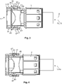
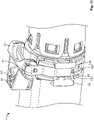
- FIG. 1 A preferred embodiment of a housing assembly 1 according to the invention is shown in Fig. 1 .
- the housing assembly 1 comprises a housing 3 having a receptacle 5 for receiving a mating connector 7 at least in parts.
- the receptacle 5 extends along an axis 9 and has an opening 11 through which it is accessible for the mating connector 7 along a receiving direction 13.
- the receiving direction 13 extends parallel with the axis 9 and defines an insertion direction 15 for the mating connector 7.
- one or more electrical contacts may be arranged for being electrically connected to mating contacts of the mating connector 7. Such contacts are not shown in the figures.
- the housing assembly 1 and said electric contacts may form at least parts of an electrical connector 2.
- the housing 3 may be made of any suitable material. However, the housing 3 is preferably made from aluminum or a thermoplastic material.
- the housing assembly 1 comprises a connector position assurance element 17, or CPA 17, for securing the position of the mating connector 7 in the receptacle 5.
- the CPA 17 can be moved from a locking position 19, which is shown in Figures 1 to 5 , to a release position 21, which is shown in Figures 6 to 9 .
- the housing assembly 1 further comprises preferably one CPA-actuator 23 that is operationally coupled to the CPA 17 and adapted for driving the CPA 17 from the locking position 19 to the release position 21.
- the CPA 17 is moved away from the receptacle 5 in relation to the locking position 19. This will be described later on with respect to Figures 6 to 9 .
- the CPA 17 is spring-biased into the locking position 19.
- the spring-bias exerts a reset force for pulling the CPA 17 back into the locking position 19.
- the spring bias moves the CPA 17 from the release position 21 into the locking position 19 when no external force acts on the CPA actuator 23.
- the CPA-actuator 23 is only used for moving the CPA 17 from the locking position 19 to the release position 21. Movement from the release position 21 into the locking position 19 is preferably performed only by the spring bias.
- the CPA 17 and the CPA-actuator 23 are combined unitarily with each other.
- the CPA 17 and the CPA-actuator 23 together form a unit 25.
- the unit 25 is preferably captively connected to the housing 3.
- the unit 25 is thereby preferably held by the CPA 17 on the housing 3.
- the housing 3 is provided with two CPA openings 27, through which the CPA 17 extends in parts in the locking position for a blocking a movement of the mating connector 7.
- the CPA is at least partially retracted from the CPA openings 27, at least to such an extent that the mating connector 7 may be released from the receptacle 5.
- the two openings 27 are arranged on two opposing sides of the housing diametrically across the receptacle 5.
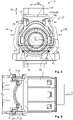
- the CPA openings 27 may be arranged in offset regions 29 of the housing, in which a wall 31 that forms the housing 3 is offset towards an outside of the housing 3. This can be seen in Figures 3 to 5 , which show cross sections of the housing 3. In the locking position 19 and when the CPA 17 is not deformed by the mating connector 7, inner sides 33 of the CPA 17 may be flush with inner sides 35 of the housing wall 31 in sections adjacent to the offset sections 29.
- the CPA openings 27 may be arranged in grooves 37 of the housing 3, which allow a sliding movement of the CPA 17 in a CPA moving direction 39, which is perpendicular to the axis 9 of the receptacle 5.
- the grooves 37 may be formed by the offset sections 29 of the wall 31.
- the grooves 37 prevent a movement of the CPA 17 along the direction of the axis 9 of the receptacle 5.
- the grooves 37 extend basically parallel with the CPA moving direction 39.
- FIGS 3 to 5 all show the CPA 17 in the locking position 19.
- the CPA 17 is arranged in the grooves 37 on both sides of the housing 3 and reaches into the receptacle 5 through the CPA openings 27.
- the mating connector 7 is provided with complementary locking means 41 that are configured to abut the CPA 17 in the locking position 19.
- the complementary locking means 41 are configured as latching hooks 42, of which each is provided with an inclined or sloped surface 43 for deflecting the CPA 17 during insertion of the mating connector 7 into the receptacle 5.
- the insertion process of the mating connector 7 into the receptacle 5 is shown starting from Figure 3 .
- the complementary locking means 41 arrive at the CPA 17.
- the mating connector 7 is shown further introduced into the receptacle 5 along the insertion direction 15.
- the CPA 17 is widened because the sloped surfaces 43 have abutted the inner sides 33 of the CPA and thereby spread the CPA 17 through the CPA openings 27 such that at least parts of the CPA 17 have moved away from the receptacle 5.
- the abutment walls 45 preferably at least partially extend perpendicular to the insertion direction 15.
- the CPA 17 at least partially clasps the housing 3, whereby the CPA 17 preferably encompasses more than 180° of a cross-section of the receptacle 5, wherein the angle 51, at which the CPA 17 encompasses the cross-section is measured around the axis 9 of the receptacle 5.
- the CPA 17 preferably has the overall shape of a clip 53, i.e. basically the overall shape of a U-clip.
- the clip 53 has two legs 55, which are connected via a ground 57.
- the legs 55 basically extend parallel with the CPA moving direction 39.
- the ground 57 basically extends perpendicular to the legs 55 and perpendicular to the axis 9.
- the ground 57 basically extends parallel with a CPA locking direction 59, which as mentioned above, is perpendicular to the axis 9 and perpendicular to the CPA moving direction 39.
- the locking direction 59 is also the direction along which the CPA 17 is widened during insertion of the mating connector 7 as discussed with respect to Figures 3 to 5 .
- Each of the legs 55 has a locking section 61, which basically extends straight and which is basically parallel with the CPA moving direction 39, at least in the locking position 19. In the release position 21, the locking sections 61 may deviate from the parallel alignment with the CPA moving direction 39.
- each leg 55 is provided with a sliding section 63 which abuts the outer surface 65 of the housing 3.
- the outer surface 65 may be the outer surface of the wall 31.
- the distance 67 between the two legs 55 is basically smaller than the distance between the legs 55 at their locking sections 61.
- the CPA 17 is preferably configured for being elastically deformable.
- the legs 55 are preferably elastically deflectable from each other.
- the CPA 17 is configured as an elastically deflectable spring member 69.
- Said spring member 69 is configured for generating the spring bias towards the locking position 19.
- each leg 55 is configured to slide along the outer surface 65 of the housing 3.
- the housing 3 has a basically round cross section.
- the sliding sections 63 encompass the housing 3 such that the housing 3 is at least partially arranged inside the clip-shaped CPA 17. Moving the CPA 17 along the CPA moving direction 39 in the direction of the ground 57 will lead to a widening of the CPA 17 since the sliding sections 63 each follow the outer surface 65. It becomes obvious that a chord 71 which is perpendicular to the CPA moving direction 39 and measured from the contact points 73, where the sliding sections 63 abut the outer surface 65 becomes larger during a movement of the CPA 17 along the CPA moving direction 39 in the direction of the ground 57.
- the outer surface 65 of the housing 3 is inclined with respect to the CPA moving direction 39.
- These inclined sections 72 and the CPA 17 are together configured for converting a sliding movement of the sliding sections 63 along the inclined sections 72 during a transition from the locking position 19 to the release position 21 into a movement of the locking sections 61 further away from the receptacle 5.
- a movement of the CPA 17 along the CPA moving direction 39 towards the ground 57 will lead to a spreading of the locking sections 61.
- the locking sections 61 may thereby by moved far enough from the complementary locking means 41 of the mating connector 7 that the mating connector 7 may be released from the receptacle 5 without the CPA 17 blocking its movements against the insertion direction 15.
- the CPA 17 is preferably made from a strip that is formed into the shape of the CPA.
- the CPA therefore has an overall rectangular cross-section, which can be seen in the cross-sectional views of Figures 3 to 5 and 9 .
- the CPA 17 is made from steel, in particular spring steel 75.
- the locking sections 61 are arranged inside the grooves 37 such that the complementary locking means 41 from the mating connector 7 engage the locking sections 61 such that the mating connector 7 is blocked from being removed from the receptacle 5.
- the CPA-actuator 23 In the locking position, the CPA-actuator 23 is arranged in a down position 77, which is shown in Figures 1 and 2 . In said down position 77, the CPA actuator 23 may cover at least the ground 57 of the CPA 17.
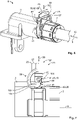
- the CPA-actuator 23 In order to move the CPA 17 from the locking position 19 to the release position 21, the CPA-actuator 23 is used.
- the CPA-actuator 23 is coupled to the CPA 17 at two joint portions 79.
- the CPA-actuator 23 is joined with the CPA 17 via two hinges 81, which allow the CPA-actuator 23 to rotate around a rotational axis 83.
- the CPA-actuator 23 may be provided with pins 85, which extend into corresponding holes 87 in the CPA 17.
- the pins 85 may also be arranged on the CPA 17 and corresponding holes 87 can be arranged in the CPA-actuator 23.
- the CPA-actuator 23 further comprises two lever members 89, of which output portions 91 are arranged between the joint portions 79 and an abutment section 93, which is preferably formed as a shoulder 95 on the housing 3.
- the CPA-actuator 23 further comprises a lever handle 97, which can be used for operating the CPA-actuator 23.
- the lever handle 97 connects the two lever members 89 with each other.
- the two lever members 89 are spaced apart from each other along the locking direction 59.
- Each of the abutment sections 93 of the housing are preferably arranged at ends of the grooves 37, said ends being oriented towards the ground 57 of the CPA 17.
- the spring force exerted by the CPA 17 pulls the CPA-actuator 23 such that it permanently abuts the abutment sections 93 with the output portions 91.
- the output portions 91 have surfaces 99 for abutting the abutment sections 93 of the housing 3 during rotation around the rotational axis 83.
- Each of the surfaces 99 runs around its corresponding joint section 79 or, in other words, around the rotational axis 83 such that a distance 101 between the rotational axis 83 and the surface 99 gradually increases.
- the distance 101 increases from a first section 103, with which the CPA-actuator 23 abuts the abutment section 93 in the locking position 19 towards a second section 105, with which the CPA-actuator 23 abuts the abutment section 93 in the release position 21.
- the sliding sections 63 slide along the outer surface 65 of the housing 3, thereby widening the CPA 17 and spreading the locking sections 61 apart from each other. Hence, the receptacle 5 is unblocked for the mating connector 7 to be removed.
- the CPA 17 Due to the spring bias, the CPA 17 generates, the CPA-actuator 23 is pulled back by the CPA 17 towards the down position 77 when no external force, for example from an operator, acts on the lever handle 97.
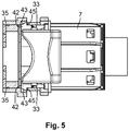
- the second embodiment of the housing assembly 1 is provided with a CPA-actuator 23 that is provided with a latching mechanism 109 for latching the CPA-actuator 23 to the housing 3 in the locking position 19.
- the latching mechanism comprises a elastically deflectable spring arm 111, a latching receptacle 113 for receiving a complementary latching member 115 of the housing 3 and an operating section 117 for disengaging the latching receptacle 113 from the latching element 115 of the housing.
- the latching receptacle 113 is arranged on a deflectable end of the spring arm 111, which exerts a spring force of the latching mechanism towards the latching element 115.
- Both the latching mechanism 109 and the latching member 115 are provided with inclined surfaces that can slide against each other when the CPA-actuator 23 is moved into the locking position 19.
- the locking member 115 When the locking position 19 is reached, the locking member 115 is arranged inside the latching receptacle 113. In order to move the CPA-actuator 23 into the release position 21 (not shown), the latching mechanism 109 must first be disengaged from the latching member 115 in order to allow movement of the CPA-actuator 23 away from the locking position 19.
- the second embodiment of the housing assembly 1 is provided with another element that increases the safety of the assembly 1.
- the CPA 17 is provided with a slit 119.
- the slit extends along the shape of the CPA 17 basically longitudinally and parallel with the corresponding leg 55.
- the slit 119 is closed to all lateral sides but extends through the CPA 17 in a radial direction with respect to the axis 9.
- the housing 3 is provided with a pin 121 for each of the slits 119.
- Each pin 121 extends into the corresponding slit 119. During movement between the locking position 19 and the release position 21, the pin 121 may slide with respect to the CPA 17 through the slit 119.
- the pin In the release position (not shown), the pin may abut a wall portion 123 of the CPA 17 which forms the lower end of the slit 119. This abutment may prevent removal of the CPA 17 from the housing 3. Thereby, the safety of the housing assembly is increased.
- the lever handle 97 of the second embodiment extends in the direction of the housing 3 instead of in the direction of the mating connector 7 as in the first described embodiment.
- the direction of CPA-actuator 23 may be chosen depending on the requirements for the housing assembly 1 and is not restricted to one direction.
Landscapes
- Details Of Connecting Devices For Male And Female Coupling (AREA)
Priority Applications (1)
| Application Number | Priority Date | Filing Date | Title |
|---|---|---|---|
| EP20199648.5A EP3979433A1 (de) | 2020-10-01 | 2020-10-01 | Gehäuseanordnung mit federvorspannungs-cpa |
Applications Claiming Priority (1)
| Application Number | Priority Date | Filing Date | Title |
|---|---|---|---|
| EP20199648.5A EP3979433A1 (de) | 2020-10-01 | 2020-10-01 | Gehäuseanordnung mit federvorspannungs-cpa |
Publications (1)
| Publication Number | Publication Date |
|---|---|
| EP3979433A1 true EP3979433A1 (de) | 2022-04-06 |
Family
ID=72717787
Family Applications (1)
| Application Number | Title | Priority Date | Filing Date |
|---|---|---|---|
| EP20199648.5A Pending EP3979433A1 (de) | 2020-10-01 | 2020-10-01 | Gehäuseanordnung mit federvorspannungs-cpa |
Country Status (1)
| Country | Link |
|---|---|
| EP (1) | EP3979433A1 (de) |
Cited By (4)
| Publication number | Priority date | Publication date | Assignee | Title |
|---|---|---|---|---|
| USD1051061S1 (en) | 2023-05-05 | 2024-11-12 | Molex, Llc | Connector |
| USD1054992S1 (en) | 2023-05-05 | 2024-12-24 | Molex, Llc | Connector |
| USD1065091S1 (en) | 2023-05-05 | 2025-03-04 | Molex, Llc | Connector |
| USD1069716S1 (en) | 2023-05-05 | 2025-04-08 | Molex, Llc | Connector |
Citations (4)
| Publication number | Priority date | Publication date | Assignee | Title |
|---|---|---|---|---|
| US5616045A (en) * | 1995-07-14 | 1997-04-01 | Augat Inc. | Squib connector for automotive air bag assembly |
| EP2026421B1 (de) * | 2007-08-13 | 2010-06-09 | Molex Incorporated | Airbagverbinder |
| WO2012007343A1 (en) * | 2010-07-16 | 2012-01-19 | Tyco Electronics France Sas | Connection with connection position assurance (cpa) device on locking element |
| US20170214168A1 (en) * | 2016-01-21 | 2017-07-27 | Tyco Electronics Corporation | Connector system with connector position assurance |
-
2020
- 2020-10-01 EP EP20199648.5A patent/EP3979433A1/de active Pending
Patent Citations (4)
| Publication number | Priority date | Publication date | Assignee | Title |
|---|---|---|---|---|
| US5616045A (en) * | 1995-07-14 | 1997-04-01 | Augat Inc. | Squib connector for automotive air bag assembly |
| EP2026421B1 (de) * | 2007-08-13 | 2010-06-09 | Molex Incorporated | Airbagverbinder |
| WO2012007343A1 (en) * | 2010-07-16 | 2012-01-19 | Tyco Electronics France Sas | Connection with connection position assurance (cpa) device on locking element |
| US20170214168A1 (en) * | 2016-01-21 | 2017-07-27 | Tyco Electronics Corporation | Connector system with connector position assurance |
Cited By (4)
| Publication number | Priority date | Publication date | Assignee | Title |
|---|---|---|---|---|
| USD1051061S1 (en) | 2023-05-05 | 2024-11-12 | Molex, Llc | Connector |
| USD1054992S1 (en) | 2023-05-05 | 2024-12-24 | Molex, Llc | Connector |
| USD1065091S1 (en) | 2023-05-05 | 2025-03-04 | Molex, Llc | Connector |
| USD1069716S1 (en) | 2023-05-05 | 2025-04-08 | Molex, Llc | Connector |
Similar Documents
| Publication | Publication Date | Title |
|---|---|---|
| EP3979433A1 (de) | Gehäuseanordnung mit federvorspannungs-cpa | |
| KR100759011B1 (ko) | 유체 이송 시스템용 커플링 | |
| EP3005486B1 (de) | Elektrischer steckverbinder | |
| RU2413121C2 (ru) | Быстродействующее соединительное устройство и средство контроля | |
| CA2303161C (en) | Electric plug and socket assembly | |
| KR100629050B1 (ko) | 커넥터 래치 | |
| US10230178B2 (en) | Cable connector | |
| KR101520147B1 (ko) | 커넥터 위치 보장 장치 | |
| CN103238255B (zh) | 连接器组件 | |
| WO2012007343A1 (en) | Connection with connection position assurance (cpa) device on locking element | |
| KR100894952B1 (ko) | 캠 레버 리테이너를 갖는 전기 커넥터 | |
| US9564704B2 (en) | Connector assembly | |
| KR101112644B1 (ko) | 잠금 기구 | |
| US12046856B2 (en) | Electrical plug device with a blocking mechanism for a position assurance element which can be released by a mating housing | |
| JP2009297511A (ja) | 自動固定コネクターシステム用雌型連結器 | |
| EP4228100B1 (de) | Verbinderanordnung mit einer detektionsfunktion für einen nicht aufliegenden anschluss | |
| US9735504B2 (en) | Electrical connector and electrical plug connection | |
| US6863551B2 (en) | Connector, set of connectors and method of connecting a connector | |
| EP4312321A1 (de) | Gehäuseanordnung für einen elektrischen steckverbinder mit einer gegenhilfe sowie elektrischer steckverbinder und steckverbinderanordnung | |
| CN115036750B (zh) | 具有小型化的连接器位置保证构件的电连接器系统 | |
| KR100995279B1 (ko) | 레버타입 커넥터어셈블리 | |
| KR100995280B1 (ko) | 레버타입 커넥터어셈블리 | |
| KR20100030416A (ko) | 레버타입 커넥터어셈블리 | |
| US20240372295A1 (en) | Securing element for a connector, connector and connector arrangement | |
| WO2025251314A1 (en) | Plug connector |
Legal Events
| Date | Code | Title | Description |
|---|---|---|---|
| PUAI | Public reference made under article 153(3) epc to a published international application that has entered the european phase |
Free format text: ORIGINAL CODE: 0009012 |
|
| STAA | Information on the status of an ep patent application or granted ep patent |
Free format text: STATUS: THE APPLICATION HAS BEEN PUBLISHED |
|
| AK | Designated contracting states |
Kind code of ref document: A1 Designated state(s): AL AT BE BG CH CY CZ DE DK EE ES FI FR GB GR HR HU IE IS IT LI LT LU LV MC MK MT NL NO PL PT RO RS SE SI SK SM TR |
|
| STAA | Information on the status of an ep patent application or granted ep patent |
Free format text: STATUS: REQUEST FOR EXAMINATION WAS MADE |
|
| 17P | Request for examination filed |
Effective date: 20220930 |
|
| RBV | Designated contracting states (corrected) |
Designated state(s): AL AT BE BG CH CY CZ DE DK EE ES FI FR GB GR HR HU IE IS IT LI LT LU LV MC MK MT NL NO PL PT RO RS SE SI SK SM TR |
|
| STAA | Information on the status of an ep patent application or granted ep patent |
Free format text: STATUS: EXAMINATION IS IN PROGRESS |
|
| 17Q | First examination report despatched |
Effective date: 20240206 |