EP3979875B1 - Strukturelement mit elektrisch leitenden eigenschaften und verfahren zu dessen verwendung - Google Patents
Strukturelement mit elektrisch leitenden eigenschaften und verfahren zu dessen verwendung Download PDFInfo
- Publication number
- EP3979875B1 EP3979875B1 EP20730400.7A EP20730400A EP3979875B1 EP 3979875 B1 EP3979875 B1 EP 3979875B1 EP 20730400 A EP20730400 A EP 20730400A EP 3979875 B1 EP3979875 B1 EP 3979875B1
- Authority
- EP
- European Patent Office
- Prior art keywords
- structural element
- conductive layer
- contact
- socket
- electrical
- Prior art date
- Legal status (The legal status is an assumption and is not a legal conclusion. Google has not performed a legal analysis and makes no representation as to the accuracy of the status listed.)
- Active
Links
Images


Classifications
-
- A—HUMAN NECESSITIES
- A47—FURNITURE; DOMESTIC ARTICLES OR APPLIANCES; COFFEE MILLS; SPICE MILLS; SUCTION CLEANERS IN GENERAL
- A47B—TABLES; DESKS; OFFICE FURNITURE; CABINETS; DRAWERS; GENERAL DETAILS OF FURNITURE
- A47B96/00—Details of cabinets, racks or shelf units not covered by a single one of groups A47B43/00 - A47B95/00; General details of furniture
- A47B96/14—Bars, uprights, struts, or like supports, for cabinets, brackets, or the like
- A47B96/145—Composite members, i.e. made up of several elements joined together
-
- A—HUMAN NECESSITIES
- A47—FURNITURE; DOMESTIC ARTICLES OR APPLIANCES; COFFEE MILLS; SPICE MILLS; SUCTION CLEANERS IN GENERAL
- A47B—TABLES; DESKS; OFFICE FURNITURE; CABINETS; DRAWERS; GENERAL DETAILS OF FURNITURE
- A47B96/00—Details of cabinets, racks or shelf units not covered by a single one of groups A47B43/00 - A47B95/00; General details of furniture
- A47B96/20—Furniture panels or like furniture elements
- A47B96/205—Composite panels, comprising several elements joined together
- A47B96/206—Composite panels, comprising several elements joined together with laminates comprising planar, continuous or separate layers
-
- H—ELECTRICITY
- H01—ELECTRIC ELEMENTS
- H01R—ELECTRICALLY-CONDUCTIVE CONNECTIONS; STRUCTURAL ASSOCIATIONS OF A PLURALITY OF MUTUALLY-INSULATED ELECTRICAL CONNECTING ELEMENTS; COUPLING DEVICES; CURRENT COLLECTORS
- H01R25/00—Coupling parts adapted for simultaneous co-operation with two or more identical counterparts, e.g. for distributing energy to two or more circuits
- H01R25/14—Rails or bus-bars constructed so that the counterparts can be connected thereto at any point along their length
- H01R25/147—Low voltage devices, i.e. safe to touch live conductors
Definitions
- the present invention relates to the field of structural elements, in particular wood chip structural elements for furniture and interior design, according to the preambles of the patent claims, the use of such structural elements and a method for producing such structural elements as well as methods for electrical energy supply using such structural elements.
- a typical supply of electrical consumers is realized by cables that are laid along structural elements of a piece of furniture and/or embedded in it, up to the consumer.
- the cables are electrically connected to the supply unit normally used, thereby supplying the consumer with electrical energy.
- conductor rails in which a contacting device or socket is inserted between two spaced-apart conductor rails, which connects the conductor rails separately and individually with their contact elements. electrically contacted.
- the socket can be positioned along the conductor rail pair.
- Conductor rail pairs can be attached to furniture and connected to a supply unit that is customary for use. Electrical consumers can be electrically connected to the socket, in this way a power supply is provided for consumers on pieces of furniture.
- FR2601519A1 published in 1988 in the names of Alain Delache and Veronique Castelo relates to a device for simultaneously connecting and supplying an electric current to a group of light-emitting diodes, characterized in that it consists of a film obtained by superimposing two layers of electrically conductive spongy materials. These layers are separated and covered by layers of insulating spongy materials, and the layers of conductive materials are connected to an electric current source via a transformer.
- the diodes are fed via the layers of conductive material by simply inserting their leads (pins) into the film, the first lead (pin) ending in the first of the conductive layers while the other reaches the second layer after passing through the first through an insulating sheath.
- EP0109852A2 published in 1984 in the name of University College Cambridge Consultants Ltd. relates to a display device for maps, notes, drawings and the like comprising one or more layers C of insulating material sandwiched between layers of electrically conductive material B.
- a light emitting device can be used to illuminate something A located on the outer conductive layer and supplied with electricity via the layers B.
- WO2008150381A1 published on 12/11/2008 in the names of Roy A. Smith and Kenneth 1.
- Smith relates to an electrical power platform consisting of an upper conductive layer, a lower conductive layer, and a non-conductive insulating layer sandwiched between the conductive layers.
- Light emitting diodes each having a short lead and an upper insulated long lead, can be removably attached to, displayed on, and powered by the power platform by inserting leads into the display surface of the power platform.
- AT11284U1 was published on July 15, 2010 in the name of Team 7 with Washen GmbH and relates to an electrical connection device for a composite panel, which comprises two electrically conductive layers between a core and two cover layers, with a contact bolt that has two contact sections that are electrically insulated from one another, each for one of the electrically conductive layers.
- the contact bolt is designed as a threaded bolt with a flattened base between the individual turns of the thread.
- US6657381 B1 was published on February 2, 2003 and describes a display device including a multilayer structure and a plurality of light emitting devices mounted on a display surface of the multilayer structure.
- the multilayer structure includes stacked first, second and third insulating layers, a first conductive layer interposed between the second and third insulating layers, and a second conductive layer interposed between the second and third insulating layers.
- each of the first and second conductive layers is a layer of fibers into which a needle or the like can be pierced.
- a disadvantage of the arrangements known from the state of the art is the limited positioning of the electrical consumers on the piece of furniture, or their power supply.
- An object of the invention is to provide a structural element, in particular for use in pieces of furniture, which improves the state of the art in the field of energy supply of electrical consumers, as well as their arrangement and positionability on pieces of furniture.
- the invention with its at least two electrically conductive layers, enables a freely positionable tap of electrical voltage on the structural element, in particular on a structural element plate, for operating electrical consumers, such as for example lighting equipment. No cable connection is required along the structural element, as it itself provides the functionality of a power conductor.
- a first aspect of the invention relates to a structural element, in particular for use in furniture.
- the structural element comprises at least a first electrically conductive layer and a second electrically conductive layer, as well as an electrically insulating separating layer, wherein the separating layer is arranged in a cross section of the structural element between the first conductive layer and the second conductive layer and adjoins the first conductive layer and the second conductive layer.
- At least one of the first conductive layer and the second conductive layer comprises a mixture of binder, cellulose-containing particles and electrically conductive particles.
- the at least three layers that the structural element has can be formed over the entire surface, depending on the embodiment, and partially in other embodiments.
- the first and second conductive layers can be congruent with the electrically insulating separating layer in a top view.
- the first and/or second conductive layers cover only part of the surface of the insulating separating layer in a top view.
- the insulating separating layer can comprise several layers and, when viewed in cross section, can have a layered structure; in particular, the use of plywood for the separating layer is conceivable.
- the layers differ from the adjacent ones by their material or materials and/or by their weight-proportional composition.
- the structural element can be constructed in layers when viewed in cross-section.
- conductive and non-conductive layers lie next to each other in a plane parallel to the separating layer when viewed in elevation.
- Typical layer thicknesses are in the range of 0.3 mm to 50 mm, especially 1 mm to 6 mm.
- the structural element has 5 or more layers, of which only two layers have a higher electrical conductivity than the remaining layers.
- the structural element comprises a number of electrically conductive layers, the number being greater than two and an electrically insulating separating layer being provided between adjacent electrically conductive layers.
- Such an embodiment is particularly suitable for the separate energy supply of several electrical consumers.
- one of the electrically conductive layers can serve as a common conductor for the consumers.
- Such a common conductor can optionally also contain a larger cross-sectional area and/or a larger proportion of electrically conductive particles with respect to the other electrically conductive layers in order to keep their electrical conductivity high or their electrical resistance low.
- Typical values for specific resistances of an electrically conductive layer comprising binders and electrically conductive particles are between 2 * 10 mm ⁇ m and 5 * 10 mm ⁇ m.
- the insulating separation layers typically have specific resistance values in the range between 1.7 * 10 m ⁇ m to 8.6 * 10 m ⁇ m.
- the separating layer comprises a mixture of binder and cellulose-containing particles.
- the cellulose-containing particles can be realized in particular by individual particles of wood, such as chips or fibers.
- Binders that can be used include, for example, aminoplast: melamine-formaldehyde resin (MF), urea-formaldehyde resin (UF), phenol-formaldehyde resin (PF), phenolresorcinol-formaldehyde resin (PRF), polymeric diphenylmethane diisocyanates (PMDI), modified melamine-formaldehyde resin (MUF and MUPF).
- the use of cement and starch- or tannin-based binders is also conceivable.
- the mixture of binder and cellulose-containing particles comprises in embodiments a weight proportion of 0.1% to 30% binder, in particular a weight proportion of 1% to 12% binder.
- the separating layer comprises electrically insulating materials such as plastics, ceramic materials, glass, wood, cork, concrete, flint, lime and others.
- the separating layer consists of a mixture of binder and wood chips.
- wood has the advantage of enabling a high level of strength of the material, while at the same time offering the ecological and economic advantages that a renewable raw material offers.
- the structural element comprises at least one conductive layer which comprises a mixture of binder, cellulose-containing particles and conductive particles.
- the structural element is designed as a three-layer chipboard.
- the two outer layers, separated from each other by the middle layer, comprise a proportion of conductive particles.
- the weight fraction of conductive particles in a conductive layer of the structural element is between 1% and 50% of the weight of the layer, in particular 3% to 20%.
- the electrically conductive particles are carbon fibers.
- the conductive particles are in the form of granules, fibers, platelets, flakes or similar.
- the structural element comprises electrically conductive plastics, graphite, soot or metal particles as electrically conductive particles.
- the structural element is designed as a plate, in particular as a wood chipboard, whereby a structural element plate is also understood to mean molded parts, in particular wood chipboard molded parts, the structural element plate is a three-dimensional object with mechanical properties, in particular strength, which allows use in the respective intended field of application, in particular, for example, furniture construction.
- the structural element comprises a first contact element electrically connected to the first conductive layer and a second contact element electrically connected to the second conductive layer, wherein the first contact element and the second contact element can each be a planar element, for example a metal strip or metal plate.
- a contact element contacts a conductive layer of the structural element on one or both sides.
- the side of the contact element facing the structural element is designed in such a way that the contact and the flow of electrical current across the contact point is improved by increasing the contact surface area.
- thorn- and/or jagged elements can be formed on one side of the contact element, which are embedded in the conductive layer of the structural element, thereby increasing the contact surface area.
- the use of a metal strip in particular has the advantage that, due to its small thickness/height, it can be inserted into the electrically conductive layers without greatly increasing the overall layer thickness.
- a further advantage is the large contact area of the metal strip with the electrically conductive layer, which increases the reliability of the electrical contact between the metal strip and the electrically conductive layer.
- the large contact areas of the metal strip with the electrically conductive layer distribute the potential heat through the flow of electrical current.
- the first contact element and the second contact element each or together form an electrical connector.
- the structural element comprises an electrical consumer, in particular an electrical lighting device, wherein a first electrical connection of the electrical consumer is electrically connected to the first conductive layer and a second electrical connection of the electrical consumer is electrically connected to the second electrically conductive layer.
- the structural element comprises a plurality of consumers. These can be connected in particular in parallel to the first and second electrically conductive layers. In an arrangement with more than two conductive layers as described above, electrical consumers can each be connected individually or in groups with one of their connections to different electrically conductive layers. A second connection of all electrical consumers can, for example, be connected to a common electrically conductive layer that serves as a common (return) conductor.
- the electrical connection between the consumer and the structural element can be direct or indirect.
- Electrical consumers include consumers designed for low voltage, especially extra-low voltage.
- Typical voltages applied between the conductive layers are below 75 volts, especially between 5 volts and 50 volts.
- Typical electrical currents within the conductive layers are below 10 amperes, especially between 25 milliamperes and 1 ampere.
- the range of voltages that can be applied between the conductive layers of the structural element is the voltages considered harmless to humans, i.e. those that do not pose a danger to humans when two conductive layers come into contact at the same time.
- the structural element comprises a socket, the socket being designed to at least partially accommodate a first terminal and a second terminal of an electrical load, the first terminal of the electrical load being electrically connected to the first conductive layer and the second terminal of the electrical load being electrically connected to the second conductive layer.
- such a socket has an elongated, in particular cylindrical, basic shape with a first electrically conductive socket contact, a second electrically conductive socket contact and an insulator.
- the insulator electrically insulates the first socket contact and the second socket contact from one another, the first socket contact being electrically connected to the first electrically conductive layer and the second socket contact being electrically connected to the second electrically conductive layer.
- the socket is at least partially embedded in the first or second electrically conductive layer and the separating layer in the axial direction. In special embodiments, the socket is at least partially embedded in both electrically conductive layers and the separating layer.
- a further aspect of the invention relates to a socket, in particular for use with the structural element, which has an elongated, in particular cylindrical, basic shape with a first electrically conductive socket contact, a second electrically conductive socket contact and an insulator, wherein the insulator electrically insulates the first socket contact and the second socket contact from one another.
- the two electrically conductive socket contacts are made of metal.
- the insulator between them is made of plastic, in particular, wherein the plastic with its electrically insulating property prevents electrical contact between the socket contacts.
- two consumer connection contacts designed as recesses for receiving two contact elements of an electrical consumer, in particular an electrical lamp, are located on a base side of the socket.
- a recess on one side for the consumer connection contacts on a base side which is open on one side and borders on both socket contacts.
- This recess can be used to accommodate an electrical consumer, in particular an electrical light source, wherein the consumer connection contacts are designed in such a way that they make electrical contact separately and only with one of the electrical contacts of the electrical consumer.
- a thread and/or a form-fitting structure is formed on a lateral surface of the socket. This serves to enable the socket to be inserted or screwed into recesses provided for this purpose, in particular holes that are open on one side (blind holes or blind bores) or holes that are open on both sides (through holes or through bores).
- the electrically conductive socket contacts make electrical contact separately and only with one of the electrically conductive layers of the structural element when the socket is embedded in the structural element.
- a further aspect of the invention relates to the use of a structural element for the production of furniture, ceiling or wall coverings or in vehicle construction.
- Another aspect of the invention relates to a method for supplying an electrical consumer, the method comprising an electrical energy transmission by means of a structural element.
- the consumer is connected to the conductive layers of the structural element, a difference in electrical potential is applied between the layers and an electrical current flows through the consumer.
- a further aspect of the invention relates to a piece of furniture using at least one structural element as previously described in various embodiments.
- a structural element 1 which comprises the layers 2, 3, 4 and 21 and is designed as a chipboard. It can also be seen that these layers of the structural element can be formed both over the entire surface, like layers 2 and 3, and partially, like layers 21 and 4.
- the layers 2 and 21 are in the Figure 1
- the structural element shown has electrically conductive layers which are separated from one another by an insulating layer 3.
- the layers 2, 21 comprise a proportion of electrically conductive carbon fibers and are at least partially separated from one another only by at least one electrically insulating separating layer 3.
- the conductive layers 2, 21 are typically thinner than the insulating layer 3.
- the 2, 3, 4 and 21 comprise a proportion of wood chips and binding agents.
- FIG 2 shows a perspective side view of a socket 11, the socket contacts 12 and 17 are electrically conductive and separated from each other by the insulator 13 between them, which is not electrically conductive.
- On the top of the socket there is a connection for an electrical consumer, in particular a plug connection for a light source.
- the connection pins 32, 33 of the consumer can be inserted into the recesses 18 and 19 provided for this purpose on the top of the socket 11 and make electrical contact with the socket contacts 12 and 17 of the socket 11 without forming a short circuit between the socket contacts 12 and 17.
- the socket 11 can comprise a thread 14 on its outer surface, which allows screwing into recesses provided for this purpose.
- FIGs 3 and 4 show the socket 11 in cross section with an electrical consumer 31 connected to it, in particular a lighting device.
- the consumer 31 is in electrical contact with the socket contacts 12 and 17, whereby an electrical contact is established between the first consumer contact 33 and a first socket contact 17, as well as between the second consumer contact 32 and the second socket contact 12.
- the consumer connection contacts 18 and 19 each receive one of the consumer contacts 32 and 33.
- the socket contacts 12 and 17 can, as in Figure 3 be designed as upper and lower sections of the elongated frame, with the insulator 13 located therebetween.
- Figure 4 shows ring-shaped socket contacts 12 and 17, which are formed on the upper and lower edges on the outside of the cylindrical surface of the socket 11 and are embedded in the insulator.
- the socket contact 12 or 17 is electrically connected to the consumer connection contact 18 or 19.
- a socket 11 is inserted, in particular screwed, into a recess in a structural element plate comprising the structural element.
- the structural element further comprises at least one electrical contact element 15 or 16 for each of the electrically conductive layers 2 and 22.
- the contact elements 15 and 16 comprise an electrically conductive material, in particular a metal, in particular copper, and are flat.
- the contacts 15 and 16 lie partially within the respective layer 2 and 22 and are in electrical contact with the respective electrically conductive layer 2 and 22 to which they are each firmly connected.
- the contact elements 15 and 16 can each or together form an electrical connector (not shown).
- the socket 11 contacts a first electrically conductive layer 22 of the structural element 1 with a first electrically conductive socket contact 17 and a second electrically conductive socket contact 12 of the socket 11 contacts a second electrically conductive layer 2 of the structural element 1, so that the voltage is transferred to the conductive socket contacts 12 and 17 of the socket 11.
- the insulator 13 of the socket 11 located between them insulates the socket contacts 12 and 17 from one another and prevents the socket contacts 12 and 17 from short-circuiting.
Landscapes
- Laminated Bodies (AREA)
Description
- Die vorliegende Erfindung bezieht sich auf das Gebiet der Strukturelemente, insbesondere Holzspanstrukturelemente für den Möbel- und Innenausbau, gemäss den Oberbegriffen der Patentansprüche, die Verwendung solcher Strukturelemente und ein Verfahren zur Herstellung solcher Strukturelemente sowie Verfahren zur elektrischen Energieversorgung unter Nutzung solcher Strukturelemente.
- Im Stand der Technik werden verschiedene Möglichkeiten zur elektrischen Energieversorgung von elektrischen Verbrauchern in Möbeln, sowie deren Anordnung beschrieben.
- Eine typische Versorgung elektrischer Verbraucher wird von Kabelleitungen realisiert, welche an Strukturelementen eines Möbelstücks entlang oder/und darin eingebettet, bis zum Verbraucher, verlegt werden. Die Kabel werden mit der für die Verwendung üblichen Versorgungseinheit elektrisch verbunden und dadurch der Verbraucher mit elektrischer Energie versorgt.
- Eine weitere bekannte Möglichkeit stellen Leiterschienen dar, hierbei wird zwischen zwei voneinander beabstandeten Leiterschienen eine Kontaktierungsvorrichtung bzw. Fassung eingesetzt welche die Leiterschienen separat und jeweils einzeln mit ihren Kontaktelementen elektrisch kontaktiert. Dabei ist die Fassung entlang des Leiterschienenpaares positionierbar. Leiterschienenpaare können an Möbeln angebracht und mit einer für die Verwendung üblichen Versorgungseinheit verbunden werden. Mit der Fassung können elektrische Verbraucher elektrisch verbunden werden, auf diese Weise wird eine Energieversorgung von Verbrauchern an Möbelstücken bereitgestellt.
- Nachfolgend werden Beispiele aus dem Stand der Technik kurz beschrieben.
-
FR2601519A1 -
EP0109852A2 veröffentlicht 1984 im Namen der University College Cardiff Consultants Ltd. betrifft eine Anzeigevorrichtung für Karten, Notizen, Zeichnungen und dergleichen bestehend aus einer oder mehreren Schichten C aus Isoliermaterial, die zwischen Schichten aus elektrisch leitfähigem Material B angeordnet sind. Eine Lichtemissionsvorrichtung kann verwendet werden, um etwas A zu beleuchten, das sich auf der äußeren leitfähigen Schicht befindet und über die Schichten B elektrisch versorgt wird. -
WO2008150381A1 veröffentlicht am 11.12.2008im Namen von Roy A.Smith und Kenneth 1. Smith betrifft eine elektrische Stromversorgungsplattform, die aus einer oberen leitenden Schicht, einer unteren leitenden Schicht und einer nicht leitenden isolierenden Schicht besteht, die zwischen den leitenden Schichten liegt. Leuchtdioden (LEDs), die jeweils eine kurze Leitung und eine obere isolierte lange Leitung haben, können abnehmbar an der Energieplattform befestigt, angezeigt und von dieser mit Strom versorgt werden, indem Leitungen in die Anzeigefläche der Energieplattform eingeführt werden. -
AT11284U1 -
US6657381 B1 wurde am 02.1 2.2003 veröffentlicht und beschreibt eine Anzeigevorrichtung, die eine mehrschichtige Struktur und eine Vielzahl von lichtemittierenden Vorrichtungen enthält, die auf einer Anzeigeoberfläche der mehrschichtigen Struktur angebracht sind. Die mehrschichtige Struktur umfasst aufeinander gestapelte erste, zweite und dritte Isolierschichten, eine erste leitende Schicht, die zwischen der zweiten und dritten Isolierschicht liegt, und eine zweite leitende Schicht, die zwischen der zweiten und dritten Isolierschicht liegt. Außerdem ist jede der ersten und zweiten leitenden Schichten eine Schicht aus Fasern, in die eine Nadel oder ähnliches gestochen werden kann. - Nachteilig an den vom Stand der Technik bekannten Anordnungen ist eingeschränkte Positionierbarkeit der elektrischen Verbraucher am Möbelstück, bzw. deren Energieversorgung.
- Eine Aufgabe der Erfindung besteht darin ein Strukturelement, insbesondere zur Verwendung in Möbelstücken, bereitzustellen, das den Stand der Technik im Bereich der Energieversorgung von elektrischen Verbrauchern, sowie deren Anordnung und Positionierbarkeit an Möbelstücken verbessert.
- Diese Aufgabe wird durch die Merkmale des in den unabhängigen Patentansprüchen definierten Strukturelements, sowie dem Verfahren zu dessen Verwendung und Herstellung, gelöst.
- Weitere vorteilhafte Ausführungsformen ergeben sich aus den abhängigen Ansprüchen, der Beschreibung, sowie den Zeichnungen.
- Die Erfindung ermöglicht mit ihren mindestens zwei elektrisch leitfähigen Schichten einen auf dem Strukturelement, insbesondere auf einer Strukturelementplatte, frei positionierbaren Abgriff von elektrischer Spannung zum Betrieb von elektrischen Verbrauchern, wie beispielsweise Beleuchtungsmitteln. Es wird keine Kabelverbindung entlang des Strukturelements benötigt, da dieses selbst die Funktionalität eines Stromleiters bereitstellt.
- Dies stellt eine Verbesserung gegenüber dem Stand der Technik dar.
- Ein erster Aspekt der Erfindung betrifft ein Strukturelement, insbesondere für die Verwendung in Möbelstücken. Das Strukturelement umfasst dabei mindestens eine erste elektrisch leitfähige Schicht und eine zweite elektrisch leitfähige Schicht, sowie eine elektrisch isolierende Trennschicht, wobei die Trennschicht in einem Querschnitt des Strukturelementes zwischen der ersten leitfähigen Schicht und der zweiten leitfähigen Schicht angeordnet ist und an die erste leitfähige Schicht und die zweite leitfähige Schicht angrenzt. Mindestens eine der ersten leitfähigen Schicht und der zweiten leitfähigen Schicht umfasst ein Gemisch von Bindemittel, zellulosehaltigen Teilchen und elektrisch leitfähigen Partikeln.
- Die mindestens drei Schichten, welche das Strukturelement aufweist, können je nach Ausführungsform vollflächig und in weiteren Ausführungsformen partiell ausgebildet sein. Insbesondere können die erste und die zweite leitfähige Schicht in einer Aufsicht deckungsgleich mit der elektrisch isolierenden Trennschicht sein. In weiteren Ausführungsformen bedecken die erste und/oder die zweite leitfähige Schicht in einer Aufsicht nur einen Teil der Fläche der isolierenden Trennschicht überdecken.
- In einigen Ausführungsformen kann die isolierende Trennschicht mehrere Lagen bzw. Schichten umfassen und in einem Querschnitt betrachtet einen lagigen Aufbau aufweisen, insbesondere ist dabei für die Trennschicht die Verwendung von Sperrholz denkbar.
- In anderen Ausführungsformen unterscheiden sich die Schichten von der jeweils benachbarten durch ihr Material oder Materialien und/oder durch deren im Gewicht anteiligen Zusammensetzung.
- Das Strukturelement kann in seinem Aufbau im Querschnitt betrachtet in Lagen aufgebaut sein.
- In einigen Ausführungsformen liegen in einem Aufriss betrachtet leitende und nichtleitende Schichten in einer Ebene parallel zur Trennschicht nebeneinander.
- Typische Schichtdicken liegen in einem Bereich von 0.3 mm bis 50 mm, insbesondere 1 mm bis 6mm.
- In weiteren Ausführungsformen hat das Strukturelement 5 oder mehr Schichten, von denen nur zwei Schichten eine höhere elektrische Leitfähigkeit gegenüber den restlichen Schichten aufweisen. In weiteren Ausführungsformen umfasst das Strukturelement eine Anzahl elektrisch leitfähiger Schichten, wobei die Anzahl grösser als zwei ist und zwischen jeweils benachbarten elektrisch leitfähigen Schichten eine an diese angrenzende elektrisch isolierende Trennschicht vorgesehen ist. Eine solche Ausführungsform eignet sich insbesondere zur getrennten Energieversorgung mehrerer elektrischer Verbraucher. Optional kann dabei eine der elektrisch leitfähigen Schichten als gemeinsamer Leiter für die Verbraucher dienen. Ein solcher gemeinsamer Leiter kann wahlweise ferner bezüglich der weiteren elektrisch leitfähigen Schichten eine grössere Querschnittsfläche und/oder einen grösseren Anteil elektrisch leitfähiger Partikel enthalten um ihre elektrische Leitfähigkeit hoch bzw. ihren elektrischen Widerstand gering zu halten.
- Typische Werte für spezifische Wiederstände eine der Bindemittel und elektrisch leitfähige Partikel umfassenden elektrische leitfähigen Schichten liegen zwischen 2 * 10mmΩm bis 5 * 10mmΩm.
- Die isolierenden Trennschichten haben typischerweise Werte für den für spezifische Wiederstände im Bereich zwischen 1.7 * 10mΩm bis 8.6 * 10mΩm.
- In einigen Ausführungsformen umfasst die Trennschicht ein Gemisch von Bindemittel und zellulosehaltigen Teilchen. Die zellulosehaltigen Teilchen können insbesondere durch Einzelteilchen aus Holz, wie Späne oder Fasern realisiert werden. Als Bindemittel können beispielsweise Aminoplast: Melamin-Formaldehydharz (MF), Harnstoff-Formaldehydharz (UF), Phenol-Formaldehydharze (PF), Phenolresorcin-Formaldehydharz (PRF), polymere Diphenylmethan-Diisocyanate (PMDI), modifizierte Melamin-Formaldehydharz (MUF und MUPF) verwendet werden, denkbar ist auch die Verwendung von Zement, sowie stärke- oder tanninbasierte Bindemittel. Das Gemisch von Bindemittel und zellulosehaltigen Teilchen umfasst in Ausführungen einen Gewichtsanteil von 0.1 % bis 30% Bindemittel, insbesondere einen Gewichtsanteil von 1% bis 1 2% Bindemittel.
- In anderen Ausführungsformen umfasst die Trennschicht elektrisch isolierende Materialien wie Kunststoffe, Keramische Werkstoffe, Glas, Holz, Kork, Beton, Feuerstein, Kalk und weitere.
- In einigen Ausführungsformen besteht die Trennschicht aus einem Gemisch von Bindemittel und Holzspänen.
- Holz hat in dieser Verwendung den Vorteil eine hohe Festigkeit des Werkstoffs zu ermöglichen, bei gleichzeitigen ökologischen und ökonomischen Vorteilen, welche ein nachwachsender Rohstoff bietet.
- Erfindungsgemäss umfasst das Strukturelement mindestens eine leitfähige Schicht, die ein Gemisch von Bindemittel, zellulosehaltigen Teilchen und leitfähigen Partikeln umfasst.
- In weiteren Ausführungsformen ist das Strukturelement als drei Schichten umfassende Holzspanplatte ausgebildet. Wobei die zwei aussenliegenden Schichten, durch die mittlere Schicht voneinander separierten Schichten, einen Anteil leitfähiger Partikeln umfassen.
- In einigen Ausführungen ist der Gewichtsanteil leitfähiger Partikel in einer Leitfähigen Schicht des Strukturelements zwischen 1 % und 50% des Gewichts der Schicht, insbesondere 3% bis 20%.
- In einigen Ausführungsformen des Strukturelements sind die elektrisch leitfähigen Partikel Kohlefasern.
- An die Kohlefasern für die Verwendung in einer leitfähigen Schicht des Werkstoffs werden keine Ansprüche hinsichtlich ihrer Festigkeit gestellt und Werkstoffe wie beschrieben können aus relativ kostengünstigen Ausgangsstoffen hergestellt werden.
- Typischerweise liegen die leitfähigen Partikel in Form von Granulat, Fasern, Plättchen, Flocken oder Ähnlichem vor.
- In anderen Ausführungsformen umfasst das Strukturelement als elektrisch leitfähige Partikel elektrisch leitfähigen Kunststoffe, Graphit-, Russ- oder Metallpartikel.
- In weiteren Ausführungsformen ist das Strukturelement als Platte ausgebildet, insbesondere als Holzspanplatte, wobei unter einer Strukturelementplatte auch Formteile verstanden werden, insbesondere Holzspanformteile, es handelt sich bei der Strukturelementplatte um ein dreidimensionales Objekt mit mechanischen Eigenschaften, insbesondere Festigkeit, welche eine Verwendung in dem jeweils vorgesehenen Anwendungsbereich, insbesondere etwa dem Möbelbau, erlaubt.
- In einigen Ausführungsformen umfasst das Strukturelement ein mit der ersten leitfähigen Schicht elektrisch verbundenes erstes Kontaktelement und ein mit der zweiten leitfähigen Schicht elektrisch verbundenes zweites Kontaktelement, wobei das erste Kontaktelement und das zweite Kontaktelement jeweils insbesondere ein flächiges Element sein können, beispielsweise ein Metallband oder Metallplättchen.
- In einigen Ausführungsformen kontaktiert ein Kontaktelement einseitig oder zweiseitig eine leitfähige Schicht des Strukturelements.
- Dabei ist bei einigen Ausführungsformen der einseitigen Kontaktierung zwischen Kontaktelement und leitfähiger Schicht des Strukturelements, die dem Strukturelement zugewandte Seite des Kontaktelements derart ausgebildet, dass die Kontaktierung, sowie der Fluss von elektrischem Strom über die Kontaktstelle durch Kontaktoberflächenvergrösserung verbessert wird. Beispielsweise können auf der einen Seite des Kontaktelements dornen- und/oder zackenförmige Elemente ausgebildet sein, die in die leitende Schicht des Strukturelements eingebettet werden und dadurch die Kontaktoberfläche vergrössert.
- In einigen Ausführungsformen ergibt sich speziell aus der Verwendung eines Metallbands der Vorteil, dass dieses aufgrund seiner geringen Dicke/Höhe in die elektrisch leitfähigen Schichten einfügbar ist, ohne die Gesamtschichtdicke stark zu vergrössern. Ein weiterer Vorteil besteht in der grossen Kontaktfläche des Metallbands mit der elektrisch leitfähigen Schicht, welche die Zuverlässigkeit der elektrischen Kontaktierung zwischen Metallband und elektrisch leitfähigen Schicht erhöht. Zusätzlich wird durch die grossen Kontaktflächen des Metallbands mit der elektrisch leitfähigen Schicht die potentielle Wärme durch elektrischen Stromfluss verteilt.
- In einigen Ausführungsformen des Strukturelements bilden das erste Kontaktelement und das zweite Kontaktelement jeweils oder gemeinsam einen elektrischen Steckverbinder aus.
- Dabei ergibt sich der Vorteil, dass Strukturelemente direkt über den elektrischen Steckverbinder an eine für die Verwendung übliche Versorgungseinheit, beispielsweise ein Netzteil angeschlossen werden können.
- In einigen Ausführungsformen umfasst das Strukturelement einen elektrischen Verbraucher, insbesondere ein elektrisches Leuchtmittel, wobei ein erster elektrischer Anschluss des elektrischen Verbrauchers mit der ersten leitfähigen Schicht elektrisch verbunden ist und ein zweiter elektrischer Anschluss des elektrischen Verbrauchers mit der zweiten elektrisch leitfähigen Schicht elektrisch verbunden ist. In weiteren Ausführungsformen umfasst das Strukturelement eine Mehrzahl von Verbrauchern. Diese können insbesondere in Parallelschaltung mit der ersten und zweiten elektrisch leitfähigen Schicht verbunden sein. In einer Anordnung mit mehr als zwei leitfähigen Schichten wie oben beschrieben können elektrische Verbraucher jeweils einzeln oder Gruppenweise mit einem ihrer Anschlüsse mit verschiedenen elektrisch Leitfähigen Schichten verbunden sein. Ein zweiter Anschluss aller elektrischen Verbraucher kann z. B. jeweils mit einer als gemeinsamer (Rück-)Leiter dienenden gemeinsamen elektrisch leitfähigen Schicht verbunden sein.
- Die elektrische Verbindung zwischen Verbraucher und Strukturelement kann unmittelbar oder mittelbar sein.
- Elektrische Verbraucher umfassen Verbraucher, die für Niederspannung, insbesondere Kleinspannung ausgelegt sind.
- Typische zwischen den leitfähigen Schichten angelegte Spannungen sind unterhalb von 75 Volt, insbesondere zwischen 5 Volt und 50 Volt.
- Typische elektrische Stromstärken innerhalb der leitfähigen Schichten sind unterhalb von 10 Ampere, insbesondere zwischen 25 Milliampere und 1 Ampere.
- Als Bereich für die anlegbaren Spannungen zwischen den leitfähigen Schichten des Strukturelements sind für den Menschen als ungefährlich betrachtete Spannungen, die bei gleichzeitiger Berührung von zwei leitenden Schichten für den Menschen keine Gefahr darstellen.
- In einigen Ausführungsformen umfasst das Strukturelement eine Fassung, wobei die Fassung zur mindestens teilweisen Aufnahme eines ersten Anschlusses und eines zweiten Anschlusses eines elektrischen Verbrauchers ausgelegt ist, wobei der erste Anschluss des elektrischen Verbrauchers mit der ersten leitfähigen Schicht und der zweite Anschluss des elektrischen Verbrauchers mit der zweiten leitfähigen Schicht elektrisch verbunden ist.
- In einigen Ausführungsformen weist eine solche Fassung eine langgestreckte, insbesondere zylindrische, Grundform mit einem ersten elektrisch leitfähigen Fassungskontakt, einem zweiten elektrisch leitfähigen Fassungskontakt und einem Isolator auf. Der Isolator isoliert dabei den ersten Fassungskontakt und den zweiten Fassungskontakt elektrisch voneinander, wobei der erste Fassungskontakt mit der ersten elektrisch leitfähigen Schicht elektrisch verbunden ist und der zweite Fassungskontakt mit der zweiten elektrisch leitfähigen Schicht elektrisch verbunden ist. Die Fassung ist in axialer Richtung mindestens teilweise in die erste oder zweite elektrisch leitfähige Schicht und die Trennschicht eingebettet ist. In speziellen Ausführungsformen ist die Fassung in beide elektrisch leitfähigen Schichten sowie die Trennschicht mindestens teilweise eingebettet.
- Ein weiterer Aspekt der Erfindung betrifft eine Fassung, insbesondere zur Verwendung mit dem Strukturelement, diese hat eine langgestreckte, insbesondere zylindrische, Grundform mit einem ersten elektrisch leitfähigen Fassungskontakt, einem zweiten elektrisch leitfähigen Fassungskontakt und einem Isolator aufweist, wobei der Isolator den ersten Fassungskontakt und den zweiten Fassungskontakt voneinander elektrisch isoliert.
- In einigen Ausführungsformen sind die zwei elektrisch leitfähigen Fassungskontakte aus Metall ausgebildet. Der dazwischenliegende Isolator ist insbesondere aus Kunststoff ausgebildet, wobei der Kunststoff mit seiner elektrisch isolierenden Eigenschaft den elektrischen Kontakt zwischen den Fassungskontakten verhindert.
- In weiteren Ausführungsformen der Fassung befinden sich auf einer Grundseite der Fassung zwei als Aussparungen ausgebildete Verbraucheranschlusskontakte zur Aufnahme von zwei Kontaktelementen eines elektrischen Verbrauchers, insbesondere eines elektrischen Leuchtmittels.
- In anderen Ausführungsformen befindet sich auf einer Grundseite eine einseitig offene Aussparung für die Verbraucheranschlusskontakte, welche an beide Fassungskontakte angrenzt. Diese Aussparung kann zur Aufnahme eines elektrischen Verbrauchers, insbesondere eines elektrischen Leuchtmittels, dienen, wobei die Verbraucheranschlusskontakte derart ausgebildet sind, dass diese separat und nur mit jeweils einem der elektrischen Kontakte des elektrischen Verbrauchers elektrisch kontaktieren.
- In weiteren Ausführungsformen ist auf einer Mantelfläche der Fassung ein Gewinde und/oder eine Formschlussstruktur ausgebildet. Diese dient der formschlüssigen Einsetzbarkeit oder dem Einschrauben der Fassung in dafür vorgesehene Aussparungen, insbesondere einseitig offene Löcher (Sacklöcher bzw. Sackbohrungen), oder zweiseitig offenen Löcher (Durchgangslöcher bzw. Durchgangsbohrungen).
- Dabei kontaktieren die elektrisch leitfähigen Fassungskontakte separat und nur mit jeweils einer der elektrisch leitfähigen Schichten des Strukturelements elektrisch, wenn die Fassung in das Strukturelement eigebettet ist.
- Ein weiterer Aspekt der Erfindung betrifft die Verwendung eines Strukturelements zur Herstellung von Möbelstücken, Decken- oder Wandverkleidungen oder im Fahrzeugbau.
- Ein anderer Aspekt der Erfindung betrifft ein Verfahren zur Versorgung eines elektrischen Verbrauchers, das Verfahren umfassend eine elektrische Energieübertragung mittels eines Strukturelementes.
- Dabei ist der Verbraucher mit den leitenden Schichten des Strukturelements verbunden, zwischen den Schichten ist eine Differenz im elektrischen Potential angelegt und ein elektrischer Strom fliesst durch den Verbraucher.
- Ein weiterer Aspekt der Erfindung betrifft ein Möbelstück unter Verwendung mindestens eines Strukturelements, wie es zuvor in verschiedenen Ausführungsformen beschrieben wurde.
- Anhand der in den nachfolgenden Figuren gezeigten Ausführungsbeispiele und der dazugehörigen Beschreibung werden Aspekte der Erfindung näher erläutert. Es zeigen:
- Fig. 1
- zeigt schematisch den Querschnitt einer ebenen Werkstoffplatte mit drei Schichten;
- Fig. 2
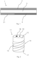
- zeigt schematisch eine Fassung mit Gewinde
- Fig. 3
- zeigt einen Querschnitt der Fassung
- Fig. 4
- zeigt einen Querschnitt der Fassung
- Fig. 5
- zeigt schematisch eine Fassung mit Gewinde eingesetzt, insbesondere eingeschraubt, in den schematischen Querschnitt einer ebenen Werkstoffplatte.
- In
Figur 1 ist ein Strukturelement 1 dargestellt, das die Schichten 2,3,4 und 21 umfasst, und als Holzspanplatte ausgebildet ist. Ferner ist zusehen, dass diese Schichten des Strukturelements sowohl vollflächig, wie Schichten 2 und 3, als auch partiell ausgebildet sein kann, wie es die Schichten 21 und 4 sind. Die Schichten 2 und 21 sind beim der inFigur 1 dargestellten Strukturelement elektrisch leitfähige Schichten, welche durch eine isolierende Schicht 3 voneinander separiert sind. Die Schichten 2, 21 umfassen dabei einen Anteil elektrisch leitfähiger Kohlefasern und liegen sich zumindest teilweise nur durch mindestens eine elektrisch isolierende Trennschicht 3 getrennt gegenüber. Die leitfähigen Schichten 2, 21 sind typischerweise dünner ausgebildet als die isolierende Schichte 3. Die 2,3,4 und 21 umfassen einen Anteil Holzspäne und Bindemittel. -
Figur 2 zeigt eine perspektivische Seitenansicht einer Fassung 11, die Fassungskontakte 12 und 17 sind elektrisch leitfähig und durch den dazwischenliegenden Isolator 13, welcher nicht elektrisch leitfähig ist, voreinander separiert. Auf der Oberseite der Fassung befindet sich ein Anschluss für einen elektrischen Verbraucher, insbesondere ein Steckanschluss für ein Leuchtmittel. Die Anschlussstifte 32, 33 des Verbrauchers können dabei in die dafür vorgesehenen Aussparungen 18 und 19 auf der Oberseite der Fassung 11 eingeführt werden und mit den Fassungskontakten 12 und 17 der Fassung 11 elektrisch kontaktieren, ohne einen Kurzschluss zwischen den Fassungskontakten 12 und 17 zu bilden. - Weiter kann die Fassung 11 ein Gewinde 14 auf deren Mantelfläche umfassen, welches ein Einschrauben in dafür vorgesehene Aussparungen erlaubt.
-
Figuren 3 und 4 zeigen die Fassung 11 im Querschnitt mit einem daran angeschlossenen elektrischen Verbraucher 31, insbesondere einem Beleuchtungsmittel. Der Verbraucher 31 ist in elektrischem Kontakt mit den Fassungskontakten 12 und 17, dabei ist ein elektrischer Kontakt zwischen dem ersten Verbraucherkontakt 33 und einem ersten Fassungskontakt 17, sowie zwischen dem zweiten Verbraucherkontakt 32 und dem zweiten Fassungskontakt 12 hergestellt. Die Verbraucheranschlusskontakte 18 und 19 nehmen dabei jeweils einen der Verbraucherkontakte 32 und 33 auf. Die Fassungskontakte 12 und 17 können, wie inFigur 3 zusehen als obere- und untere Abschnitte der länglichen Fassung ausgebildet sein, mit dem Dazwischenliegenden Isolator 13.Figur 4 hingegen zeigt ringförmig Fassungskontakte 12 und 17, die am oberen- und unteren Rand Aussen an der zylinderförmigen Mantelfläche der Fassung 11 ausgebildet und in den Isolator eingebettet sind. Der Fassungskontakt 12 bzw. 17 ist mit dem Verbraucheranschlusskontakt 18 bzw. 19 elektrisch verbunden. - In
Figur 5 ist eine Fassung 11 in eine Aussparung in einer das Strukturelement umfassenden Strukturelementplatte eingesetzt, insbesondere eingeschraubt. Das Strukturelement umfasst weiter jeweils mindestens ein elektrisches Kontaktelement 15 bzw. 16 für jede der elektrisch leitfähigen Schichten 2 und 22. Die Kontaktelemente 15 und 16 umfassen ein elektrisch leitfähiges Material, insbesondere ein Metall, insbesondere Kupfer, und sind flach ausgebildet. Die Kontakte 15 und 16 liegen partiell innerhalb der jeweiligen Schicht 2 und 22, und sind in elektrischem Kontakt mit der jeweils elektrisch leitfähigen Schicht 2 und 22 mit welcher sie jeweils fest verbunden sind. Weiter können die Kontaktelemente 15 und 16 jeweils oder gemeinsam einen elektrischen Steckverbinder (nicht dargestellt) ausbilden. - Wenn eine elektrische Spannung zwischen den Kontaktelementen 15 und 16 angelegt wird, wird diese Spannung auf die elektrisch leitenden Schichten 2 und 22 übertragen, da diese in elektrischem Kontakt mit den Kontaktelementen 15 und 16 stehen. Die Fassung 11 kontaktiert mit einem ersten elektrisch leitenden Fassungskontakt 17 eine erste elektrisch leitende Schicht 22 des Strukturelements 1 und ein zweiter elektrisch leitender Fassungskontakt 12 der Fassung 11 kontaktiert mit einer zweiten elektrisch leitenden Schicht 2 des Strukturelements 1, sodass die Spannung auf die leitenden Fassungskontakte 12 und 17 der Fassung 11 übertragen wird. Der dazwischenliegende Isolator 13 der Fassung 11 isoliert die Fassungskontakte 12 und 17 voneinander und vermeidet ein Kurzschiessen der Fassungskontakte 12 und 17. Wenn ein elektrischer Verbraucher 31 an die Fassung 11 angeschlossen wird, wird der elektrische Stromkreis bestehend aus den Kontaktelementen 15, 16, den Strukturelementschichten 2, 22, den Fassungskontakten 12, 17 und dem elektrischen Verbraucher geschlossen und ein elektrischer Strom kann fliessen.
-
- 1
- Strukturelement
- 2
- Vollflächige elektrisch leitfähige Schicht
- 3
- Elektrisch isolierende Schicht
- 4
- Partielle Schicht
- 5
- Bindemittel
- 11
- Fassung
- 12
- Fassungskontakt
- 13
- Isolator
- 14
- Gewinde
- 15
- Kontaktelement
- 16
- Kontaktelement
- 17
- Fassungskontakt
- 18
- Verbraucheranschlusskontakt
- 19
- Verbraucheranschlusskontakt
- 21
- Partielle ausgebildete elektrisch leitfähige Schicht
- 22
- Elektrisch leitfähige Schicht
- 31
- Elektrischer Verbraucher
- 32
- Elektrischer Kontakt des Verbrauchers 31
- 33
- Elektrischer Kontakt des Verbrauchers 31
Claims (13)
- Strukturelement (1), insbesondere für die Verwendung in Möbelstücken, das Strukturelement (1) umfassend:- eine erste elektrisch leitfähige Schicht (2) und eine zweite elektrisch leitfähige Schicht (21);- eine elektrisch isolierende Trennschicht (3), wobei die Trennschicht (3) in einem Querschnitt des Strukturelementes (1) zwischen der ersten leitfähigen Schicht (2) und der zweiten leitfähigen Schicht (21) angeordnet ist und an die erste leitfähige Schicht (2) und die zweite leitfähige Schicht (21) angrenzt;dadurch gekennzeichnet, dass- mindestens eine der ersten leitfähigen Schicht (2) und der zweiten leitfähigen Schicht (21) ein Gemisch von Bindemittel, zellulosehaltigen Teilchen und elektrisch leitfähigen Partikeln umfasst.
- Strukturelement (1) nach Anspruch 1, wobei die Trennschicht (3) ein Gemisch von Bindemittel und zellulosehaltigen Teilchen umfasst.
- Strukturelement (1) nach einem der vorherigen Ansprüche, wobei die elektrisch leitfähigen Partikel Kohlefasern sind.
- Strukturelement (1) nach einem der vorherigen Ansprüche, wobei das Strukturelement (1) als Strukturelementplatte ausgebildet ist.
- Strukturelement (1) nach einem der vorherigen Ansprüche, umfassend ein mit der ersten leitfähigen Schicht (2) elektrisch verbundenes erstes Kontaktelement (15) und ein mit der zweiten leitfähigen Schicht (21) elektrisch verbundenes zweites Kontaktelement (16), wobei das erste Kontaktelement (15) und das zweite Kontaktelement (16) insbesondere ein Metallband sind.
- Strukturelement (1) nach Anspruch 5, wobei das erste Kontaktelement (15) und das zweite Kontaktelement (16) jeweils oder gemeinsam einen elektrischen Steckverbinder ausbilden.
- Strukturelement (1) nach einem der vorherigen Ansprüche, wobei das Strukturelement (1) einen elektrischen Verbraucher (31), insbesondere ein elektrisches Leuchtmittel (31) umfasst, wobei ein erster elektrischer Anschluss des elektrischen Verbrauchers (31) mit der ersten leitfähigen Schicht (2) elektrisch verbunden ist und ein zweiter elektrischer Anschluss des elektrischen Verbrauchers (31) mit der zweiten elektrisch leitfähigen Schicht (21) elektrisch verbunden ist.
- Strukturelement (1) nach einem der vorherigen Ansprüche, wobei das Strukturelement (1) eine Fassung (11) umfasst, wobei die Fassung (11) zur mindestens teilweisen Aufnahme eines ersten Anschlusskontakts (32) und eines zweiten Anschlusskontakts (33) eines elektrischen Verbrauchers (31) ausgelegt ist, wobei der erste Anschluss (31) des elektrischen Verbrauchers (31) mit der ersten leitfähigen Schicht (2) und der zweite Anschluss des elektrischen Verbrauchers (33) mit der zweiten leitfähigen Schicht (21) elektrisch verbunden ist.
- Strukturelement (1) nach Anspruch 8, wobei die Fassung (11) eine langgestreckte, insbesondere zylindrische, Grundform mit einem ersten elektrisch leitfähigen Fassungskontakt (12), einem zweiten elektrisch leitfähigen Fassungskontakt (17) und einem Isolator (13) aufweist, wobei der Isolator (13) den ersten Fassungskontakt (12) und den zweiten Fassungskontakt (17) voneinander elektrisch isoliert, wobei der erste Fassungskontakt (12) mit der ersten elektrisch leitfähigen Schicht (2) elektrisch verbunden ist und der zweite Fassungskontakt (17) mit der zweiten elektrisch leitfähigen Schicht (21) elektrisch verbunden ist, wobei die Fassung in axialer Richtung mindestens teilweise in die erste elektrisch leitfähige Schicht (2) und Trennschicht (3) eingebettet ist.
- Strukturelement (1) nach Anspruch 8 oder Anspruch 9, wobei auf einer Mantelfläche der Fassung (11) ein Gewinde und/oder eine Formschlussstruktur ausgebildet ist.
- Verwendung eines Strukturelements (1) nach einem der vorhergehenden Ansprüche zur Herstellung von Möbelstücken, Decken- oder Wandverkleidungen oder im Fahrzeugbau.
- Verfahren zur Versorgung eines elektrischen Verbrauchers (31), das Verfahren umfassend eine elektrische Energieübertragung mittels eines Strukturelementes (1) nach einem der Ansprüche 1-10.
- Möbelstück hergestellt unter Verwendung mindestens eines Strukturelements nach einem der Ansprüche 1-10.
Applications Claiming Priority (2)
| Application Number | Priority Date | Filing Date | Title |
|---|---|---|---|
| CH00720/19A CH716253A2 (de) | 2019-06-04 | 2019-06-04 | Strukturelement mit elektrisch leitenden Eigenschaften und Verfahren zu dessen Verwendung zur Herstellung von Möbelstücken. |
| PCT/EP2020/064451 WO2020244953A1 (de) | 2019-06-04 | 2020-05-25 | Strukturelement mit elektrisch leitenden eigenschaften und verfahren zu dessen verwendung |
Publications (2)
| Publication Number | Publication Date |
|---|---|
| EP3979875A1 EP3979875A1 (de) | 2022-04-13 |
| EP3979875B1 true EP3979875B1 (de) | 2024-07-17 |
Family
ID=70977511
Family Applications (1)
| Application Number | Title | Priority Date | Filing Date |
|---|---|---|---|
| EP20730400.7A Active EP3979875B1 (de) | 2019-06-04 | 2020-05-25 | Strukturelement mit elektrisch leitenden eigenschaften und verfahren zu dessen verwendung |
Country Status (3)
| Country | Link |
|---|---|
| EP (1) | EP3979875B1 (de) |
| CH (1) | CH716253A2 (de) |
| WO (1) | WO2020244953A1 (de) |
Citations (1)
| Publication number | Priority date | Publication date | Assignee | Title |
|---|---|---|---|---|
| US6657381B1 (en) * | 1999-12-13 | 2003-12-02 | Makoto Arutaki | Display device having a multi-layered structure with light-emitting devices mounted thereon |
Family Cites Families (4)
| Publication number | Priority date | Publication date | Assignee | Title |
|---|---|---|---|---|
| EP0109852A3 (de) * | 1982-11-23 | 1984-12-05 | University College Cardiff Consultants Ltd. | Anzeigevorrichtung |
| FR2601519A1 (fr) * | 1986-07-11 | 1988-01-15 | Delache Alain | Dispositif d'assemblage et d'alimentation simultanes d'un groupe de diodes electroluminescentes |
| US20080298033A1 (en) * | 2007-06-01 | 2008-12-04 | Smith Roy A | Power supply platform and electronic component |
| AT11284U1 (de) * | 2009-04-15 | 2010-07-15 | Team 7 Natuerlich Wohnen Gmbh | Elektrische anschlussvorrichtung für eine verbundplatte |
-
2019
- 2019-06-04 CH CH00720/19A patent/CH716253A2/de unknown
-
2020
- 2020-05-25 EP EP20730400.7A patent/EP3979875B1/de active Active
- 2020-05-25 WO PCT/EP2020/064451 patent/WO2020244953A1/de not_active Ceased
Patent Citations (1)
| Publication number | Priority date | Publication date | Assignee | Title |
|---|---|---|---|---|
| US6657381B1 (en) * | 1999-12-13 | 2003-12-02 | Makoto Arutaki | Display device having a multi-layered structure with light-emitting devices mounted thereon |
Also Published As
| Publication number | Publication date |
|---|---|
| WO2020244953A1 (de) | 2020-12-10 |
| EP3979875A1 (de) | 2022-04-13 |
| CH716253A2 (de) | 2020-12-15 |
Similar Documents
| Publication | Publication Date | Title |
|---|---|---|
| DE1690299A1 (de) | Elektrische Leiteranordnung und Verfahren zu ihrer Herstellung | |
| DE202011000434U1 (de) | Elektrische Verbindung zwischen zwei Busbars aus ebenen Leitern und einer zwischen den Leitern angeordneten Isolationsschicht | |
| DE102016204681A1 (de) | Batterie und Verfahren zur Herstellung einer Batterie | |
| DE19952279B4 (de) | Heizdecke | |
| DE102012221689B4 (de) | Batterie mit Verbundstruktur | |
| DE102006008047B4 (de) | Kabelbaum und Zusammensetzverfahren für Kabelbäume | |
| DE102011004229A1 (de) | Dehnungsvorrichtung für Stromschienen in Niederspannungs-Schienensystemen zur Verteilung elektrischer Energie und Schienenkasten mit einer solchen Dehnungs-vorrichtung | |
| DE102015217790A1 (de) | Anordnung zur Kühlung von Batteriezellen eines Antriebsenergiespeichers eines Kraftfahrzeuges | |
| EP1844526A1 (de) | Anordnung zum erzeugen eines elektrischen stromflusses durch kohlenstofffasern | |
| EP3979875B1 (de) | Strukturelement mit elektrisch leitenden eigenschaften und verfahren zu dessen verwendung | |
| DE102017200311A1 (de) | Batterie, Trägerboard und Trägerboardelement mit Rastelementen | |
| EP0616401A1 (de) | Stromschienenpaket | |
| DE102007051410A1 (de) | Trägerrohr für Deckenelemente | |
| EP4234372B1 (de) | Bordnetz-bauteil eines kraftfahrzeuges | |
| WO2014072038A1 (de) | Leiterplattenelement und zellenanordnung | |
| DE69605215T2 (de) | Koextrudiertes Schutzblech mit metallischem Kern für Fahrrad und zugehöriges Herstellungsverfahren | |
| EP3364714A1 (de) | Beheizbares, mehrschichtiges paneel aus holz- und/oder holzersatzwerkstoffen zur herstellung eines beheizbaren fussbodens | |
| DE10316908A1 (de) | Heizvorrichtung | |
| DE202008009589U1 (de) | Beleuchtungseinheit | |
| DE102004009967A1 (de) | Kabelhalter | |
| DE102015216380A1 (de) | Elektrische Kontaktiereinrichtung sowie Verfahren zum Kontaktieren eines Flachleiters | |
| DE3211540A1 (de) | Miniaturisierte stromschiene hoher kapazitanz und verfahren zur herstellung derselben | |
| EP0057157A2 (de) | Vorrichtung, die eine frei wählbare Markierung auf Landkarten und anderen graphischen Darstellungen erlaubt | |
| DE2219131A1 (de) | Elektrische reihenklemme, insbesondere schaltanlagen-reihenklemme | |
| DE202017100846U1 (de) | Beheizbares, mehrschichtiges Paneel aus Holz- und/oder Holzersatz-Werkstoffen zur Herstellung eines beheizbaren Fußbodens |
Legal Events
| Date | Code | Title | Description |
|---|---|---|---|
| STAA | Information on the status of an ep patent application or granted ep patent |
Free format text: STATUS: UNKNOWN |
|
| STAA | Information on the status of an ep patent application or granted ep patent |
Free format text: STATUS: THE INTERNATIONAL PUBLICATION HAS BEEN MADE |
|
| PUAI | Public reference made under article 153(3) epc to a published international application that has entered the european phase |
Free format text: ORIGINAL CODE: 0009012 |
|
| STAA | Information on the status of an ep patent application or granted ep patent |
Free format text: STATUS: REQUEST FOR EXAMINATION WAS MADE |
|
| 17P | Request for examination filed |
Effective date: 20211217 |
|
| AK | Designated contracting states |
Kind code of ref document: A1 Designated state(s): AL AT BE BG CH CY CZ DE DK EE ES FI FR GB GR HR HU IE IS IT LI LT LU LV MC MK MT NL NO PL PT RO RS SE SI SK SM TR |
|
| DAV | Request for validation of the european patent (deleted) | ||
| DAX | Request for extension of the european patent (deleted) | ||
| GRAP | Despatch of communication of intention to grant a patent |
Free format text: ORIGINAL CODE: EPIDOSNIGR1 |
|
| STAA | Information on the status of an ep patent application or granted ep patent |
Free format text: STATUS: GRANT OF PATENT IS INTENDED |
|
| INTG | Intention to grant announced |
Effective date: 20231106 |
|
| GRAJ | Information related to disapproval of communication of intention to grant by the applicant or resumption of examination proceedings by the epo deleted |
Free format text: ORIGINAL CODE: EPIDOSDIGR1 |
|
| STAA | Information on the status of an ep patent application or granted ep patent |
Free format text: STATUS: REQUEST FOR EXAMINATION WAS MADE |
|
| GRAP | Despatch of communication of intention to grant a patent |
Free format text: ORIGINAL CODE: EPIDOSNIGR1 |
|
| STAA | Information on the status of an ep patent application or granted ep patent |
Free format text: STATUS: GRANT OF PATENT IS INTENDED |
|
| INTC | Intention to grant announced (deleted) | ||
| P01 | Opt-out of the competence of the unified patent court (upc) registered |
Effective date: 20240123 |
|
| INTG | Intention to grant announced |
Effective date: 20240213 |
|
| GRAS | Grant fee paid |
Free format text: ORIGINAL CODE: EPIDOSNIGR3 |
|
| GRAA | (expected) grant |
Free format text: ORIGINAL CODE: 0009210 |
|
| STAA | Information on the status of an ep patent application or granted ep patent |
Free format text: STATUS: THE PATENT HAS BEEN GRANTED |
|
| AK | Designated contracting states |
Kind code of ref document: B1 Designated state(s): AL AT BE BG CH CY CZ DE DK EE ES FI FR GB GR HR HU IE IS IT LI LT LU LV MC MK MT NL NO PL PT RO RS SE SI SK SM TR |
|
| REG | Reference to a national code |
Ref country code: CH Ref legal event code: EP |
|
| REG | Reference to a national code |
Ref country code: DE Ref legal event code: R096 Ref document number: 502020008601 Country of ref document: DE |
|
| REG | Reference to a national code |
Ref country code: IE Ref legal event code: FG4D Free format text: LANGUAGE OF EP DOCUMENT: GERMAN |
|
| REG | Reference to a national code |
Ref country code: LT Ref legal event code: MG9D |
|
| REG | Reference to a national code |
Ref country code: NL Ref legal event code: MP Effective date: 20240717 |
|
| PG25 | Lapsed in a contracting state [announced via postgrant information from national office to epo] |
Ref country code: PT Free format text: LAPSE BECAUSE OF FAILURE TO SUBMIT A TRANSLATION OF THE DESCRIPTION OR TO PAY THE FEE WITHIN THE PRESCRIBED TIME-LIMIT Effective date: 20241118 |
|
| PG25 | Lapsed in a contracting state [announced via postgrant information from national office to epo] |
Ref country code: NL Free format text: LAPSE BECAUSE OF FAILURE TO SUBMIT A TRANSLATION OF THE DESCRIPTION OR TO PAY THE FEE WITHIN THE PRESCRIBED TIME-LIMIT Effective date: 20240717 |
|
| PG25 | Lapsed in a contracting state [announced via postgrant information from national office to epo] |
Ref country code: PT Free format text: LAPSE BECAUSE OF FAILURE TO SUBMIT A TRANSLATION OF THE DESCRIPTION OR TO PAY THE FEE WITHIN THE PRESCRIBED TIME-LIMIT Effective date: 20241118 Ref country code: NL Free format text: LAPSE BECAUSE OF FAILURE TO SUBMIT A TRANSLATION OF THE DESCRIPTION OR TO PAY THE FEE WITHIN THE PRESCRIBED TIME-LIMIT Effective date: 20240717 |
|
| PG25 | Lapsed in a contracting state [announced via postgrant information from national office to epo] |
Ref country code: NO Free format text: LAPSE BECAUSE OF FAILURE TO SUBMIT A TRANSLATION OF THE DESCRIPTION OR TO PAY THE FEE WITHIN THE PRESCRIBED TIME-LIMIT Effective date: 20241017 |
|
| PG25 | Lapsed in a contracting state [announced via postgrant information from national office to epo] |
Ref country code: FI Free format text: LAPSE BECAUSE OF FAILURE TO SUBMIT A TRANSLATION OF THE DESCRIPTION OR TO PAY THE FEE WITHIN THE PRESCRIBED TIME-LIMIT Effective date: 20240717 Ref country code: PL Free format text: LAPSE BECAUSE OF FAILURE TO SUBMIT A TRANSLATION OF THE DESCRIPTION OR TO PAY THE FEE WITHIN THE PRESCRIBED TIME-LIMIT Effective date: 20240717 Ref country code: GR Free format text: LAPSE BECAUSE OF FAILURE TO SUBMIT A TRANSLATION OF THE DESCRIPTION OR TO PAY THE FEE WITHIN THE PRESCRIBED TIME-LIMIT Effective date: 20241018 |
|
| PG25 | Lapsed in a contracting state [announced via postgrant information from national office to epo] |
Ref country code: BG Free format text: LAPSE BECAUSE OF FAILURE TO SUBMIT A TRANSLATION OF THE DESCRIPTION OR TO PAY THE FEE WITHIN THE PRESCRIBED TIME-LIMIT Effective date: 20240717 |
|
| PG25 | Lapsed in a contracting state [announced via postgrant information from national office to epo] |
Ref country code: LV Free format text: LAPSE BECAUSE OF FAILURE TO SUBMIT A TRANSLATION OF THE DESCRIPTION OR TO PAY THE FEE WITHIN THE PRESCRIBED TIME-LIMIT Effective date: 20240717 |
|
| PG25 | Lapsed in a contracting state [announced via postgrant information from national office to epo] |
Ref country code: IS Free format text: LAPSE BECAUSE OF FAILURE TO SUBMIT A TRANSLATION OF THE DESCRIPTION OR TO PAY THE FEE WITHIN THE PRESCRIBED TIME-LIMIT Effective date: 20241117 |
|
| PG25 | Lapsed in a contracting state [announced via postgrant information from national office to epo] |
Ref country code: HR Free format text: LAPSE BECAUSE OF FAILURE TO SUBMIT A TRANSLATION OF THE DESCRIPTION OR TO PAY THE FEE WITHIN THE PRESCRIBED TIME-LIMIT Effective date: 20240717 |
|
| PG25 | Lapsed in a contracting state [announced via postgrant information from national office to epo] |
Ref country code: RS Free format text: LAPSE BECAUSE OF FAILURE TO SUBMIT A TRANSLATION OF THE DESCRIPTION OR TO PAY THE FEE WITHIN THE PRESCRIBED TIME-LIMIT Effective date: 20241017 Ref country code: ES Free format text: LAPSE BECAUSE OF FAILURE TO SUBMIT A TRANSLATION OF THE DESCRIPTION OR TO PAY THE FEE WITHIN THE PRESCRIBED TIME-LIMIT Effective date: 20240717 |
|
| PG25 | Lapsed in a contracting state [announced via postgrant information from national office to epo] |
Ref country code: RS Free format text: LAPSE BECAUSE OF FAILURE TO SUBMIT A TRANSLATION OF THE DESCRIPTION OR TO PAY THE FEE WITHIN THE PRESCRIBED TIME-LIMIT Effective date: 20241017 Ref country code: PL Free format text: LAPSE BECAUSE OF FAILURE TO SUBMIT A TRANSLATION OF THE DESCRIPTION OR TO PAY THE FEE WITHIN THE PRESCRIBED TIME-LIMIT Effective date: 20240717 Ref country code: NO Free format text: LAPSE BECAUSE OF FAILURE TO SUBMIT A TRANSLATION OF THE DESCRIPTION OR TO PAY THE FEE WITHIN THE PRESCRIBED TIME-LIMIT Effective date: 20241017 Ref country code: LV Free format text: LAPSE BECAUSE OF FAILURE TO SUBMIT A TRANSLATION OF THE DESCRIPTION OR TO PAY THE FEE WITHIN THE PRESCRIBED TIME-LIMIT Effective date: 20240717 Ref country code: IS Free format text: LAPSE BECAUSE OF FAILURE TO SUBMIT A TRANSLATION OF THE DESCRIPTION OR TO PAY THE FEE WITHIN THE PRESCRIBED TIME-LIMIT Effective date: 20241117 Ref country code: HR Free format text: LAPSE BECAUSE OF FAILURE TO SUBMIT A TRANSLATION OF THE DESCRIPTION OR TO PAY THE FEE WITHIN THE PRESCRIBED TIME-LIMIT Effective date: 20240717 Ref country code: GR Free format text: LAPSE BECAUSE OF FAILURE TO SUBMIT A TRANSLATION OF THE DESCRIPTION OR TO PAY THE FEE WITHIN THE PRESCRIBED TIME-LIMIT Effective date: 20241018 Ref country code: FI Free format text: LAPSE BECAUSE OF FAILURE TO SUBMIT A TRANSLATION OF THE DESCRIPTION OR TO PAY THE FEE WITHIN THE PRESCRIBED TIME-LIMIT Effective date: 20240717 Ref country code: ES Free format text: LAPSE BECAUSE OF FAILURE TO SUBMIT A TRANSLATION OF THE DESCRIPTION OR TO PAY THE FEE WITHIN THE PRESCRIBED TIME-LIMIT Effective date: 20240717 Ref country code: BG Free format text: LAPSE BECAUSE OF FAILURE TO SUBMIT A TRANSLATION OF THE DESCRIPTION OR TO PAY THE FEE WITHIN THE PRESCRIBED TIME-LIMIT Effective date: 20240717 |
|
| REG | Reference to a national code |
Ref country code: DE Ref legal event code: R082 Ref document number: 502020008601 Country of ref document: DE Representative=s name: KOELLNER, MALTE, DR., DE Ref country code: DE Ref legal event code: R082 Ref document number: 502020008601 Country of ref document: DE Representative=s name: KOELLNER, MALTE, DIPL.-PHYS. DR.RER.NAT., DE |
|
| PG25 | Lapsed in a contracting state [announced via postgrant information from national office to epo] |
Ref country code: SM Free format text: LAPSE BECAUSE OF FAILURE TO SUBMIT A TRANSLATION OF THE DESCRIPTION OR TO PAY THE FEE WITHIN THE PRESCRIBED TIME-LIMIT Effective date: 20240717 Ref country code: RO Free format text: LAPSE BECAUSE OF FAILURE TO SUBMIT A TRANSLATION OF THE DESCRIPTION OR TO PAY THE FEE WITHIN THE PRESCRIBED TIME-LIMIT Effective date: 20240717 Ref country code: DK Free format text: LAPSE BECAUSE OF FAILURE TO SUBMIT A TRANSLATION OF THE DESCRIPTION OR TO PAY THE FEE WITHIN THE PRESCRIBED TIME-LIMIT Effective date: 20240717 |
|
| REG | Reference to a national code |
Ref country code: DE Ref legal event code: R097 Ref document number: 502020008601 Country of ref document: DE |
|
| PG25 | Lapsed in a contracting state [announced via postgrant information from national office to epo] |
Ref country code: EE Free format text: LAPSE BECAUSE OF FAILURE TO SUBMIT A TRANSLATION OF THE DESCRIPTION OR TO PAY THE FEE WITHIN THE PRESCRIBED TIME-LIMIT Effective date: 20240717 |
|
| PG25 | Lapsed in a contracting state [announced via postgrant information from national office to epo] |
Ref country code: CZ Free format text: LAPSE BECAUSE OF FAILURE TO SUBMIT A TRANSLATION OF THE DESCRIPTION OR TO PAY THE FEE WITHIN THE PRESCRIBED TIME-LIMIT Effective date: 20240717 |
|
| PG25 | Lapsed in a contracting state [announced via postgrant information from national office to epo] |
Ref country code: SK Free format text: LAPSE BECAUSE OF FAILURE TO SUBMIT A TRANSLATION OF THE DESCRIPTION OR TO PAY THE FEE WITHIN THE PRESCRIBED TIME-LIMIT Effective date: 20240717 |
|
| PLBE | No opposition filed within time limit |
Free format text: ORIGINAL CODE: 0009261 |
|
| STAA | Information on the status of an ep patent application or granted ep patent |
Free format text: STATUS: NO OPPOSITION FILED WITHIN TIME LIMIT |
|
| 26N | No opposition filed |
Effective date: 20250422 |
|
| PGFP | Annual fee paid to national office [announced via postgrant information from national office to epo] |
Ref country code: DE Payment date: 20250521 Year of fee payment: 6 |
|
| PGFP | Annual fee paid to national office [announced via postgrant information from national office to epo] |
Ref country code: FR Payment date: 20250528 Year of fee payment: 6 |
|
| PGFP | Annual fee paid to national office [announced via postgrant information from national office to epo] |
Ref country code: CH Payment date: 20250601 Year of fee payment: 6 |
|
| PG25 | Lapsed in a contracting state [announced via postgrant information from national office to epo] |
Ref country code: SE Free format text: LAPSE BECAUSE OF FAILURE TO SUBMIT A TRANSLATION OF THE DESCRIPTION OR TO PAY THE FEE WITHIN THE PRESCRIBED TIME-LIMIT Effective date: 20240717 |
|
| PG25 | Lapsed in a contracting state [announced via postgrant information from national office to epo] |
Ref country code: LU Free format text: LAPSE BECAUSE OF NON-PAYMENT OF DUE FEES Effective date: 20250525 |
|
| GBPC | Gb: european patent ceased through non-payment of renewal fee |
Effective date: 20250525 |
|
| PG25 | Lapsed in a contracting state [announced via postgrant information from national office to epo] |
Ref country code: IT Free format text: LAPSE BECAUSE OF FAILURE TO SUBMIT A TRANSLATION OF THE DESCRIPTION OR TO PAY THE FEE WITHIN THE PRESCRIBED TIME-LIMIT Effective date: 20240717 |
|
| REG | Reference to a national code |
Ref country code: BE Ref legal event code: MM Effective date: 20250531 |
|
| PG25 | Lapsed in a contracting state [announced via postgrant information from national office to epo] |
Ref country code: MC Free format text: LAPSE BECAUSE OF FAILURE TO SUBMIT A TRANSLATION OF THE DESCRIPTION OR TO PAY THE FEE WITHIN THE PRESCRIBED TIME-LIMIT Effective date: 20240717 |
|
| PG25 | Lapsed in a contracting state [announced via postgrant information from national office to epo] |
Ref country code: GB Free format text: LAPSE BECAUSE OF NON-PAYMENT OF DUE FEES Effective date: 20250525 |
|
| PG25 | Lapsed in a contracting state [announced via postgrant information from national office to epo] |
Ref country code: IE Free format text: LAPSE BECAUSE OF NON-PAYMENT OF DUE FEES Effective date: 20250525 |
|
| PG25 | Lapsed in a contracting state [announced via postgrant information from national office to epo] |
Ref country code: BE Free format text: LAPSE BECAUSE OF NON-PAYMENT OF DUE FEES Effective date: 20250531 |