EP3980353B1 - Réservoir de stockage sous-marin, système d'évaluation de l'intégrité physique d'un réservoir sous-marin, procédé de détection d'une perte d'intégrité physique d'un réservoir de stockage sous-marin - Google Patents
Réservoir de stockage sous-marin, système d'évaluation de l'intégrité physique d'un réservoir sous-marin, procédé de détection d'une perte d'intégrité physique d'un réservoir de stockage sous-marin Download PDFInfo
- Publication number
- EP3980353B1 EP3980353B1 EP20764453.5A EP20764453A EP3980353B1 EP 3980353 B1 EP3980353 B1 EP 3980353B1 EP 20764453 A EP20764453 A EP 20764453A EP 3980353 B1 EP3980353 B1 EP 3980353B1
- Authority
- EP
- European Patent Office
- Prior art keywords
- tank
- insulating layer
- connection means
- flexible multilayer
- storage tank
- Prior art date
- Legal status (The legal status is an assumption and is not a legal conclusion. Google has not performed a legal analysis and makes no representation as to the accuracy of the status listed.)
- Active
Links
Images


Classifications
-
- G—PHYSICS
- G01—MEASURING; TESTING
- G01R—MEASURING ELECTRIC VARIABLES; MEASURING MAGNETIC VARIABLES
- G01R31/00—Arrangements for testing electric properties; Arrangements for locating electric faults; Arrangements for electrical testing characterised by what is being tested not provided for elsewhere
- G01R31/12—Testing dielectric strength or breakdown voltage ; Testing or monitoring effectiveness or level of insulation, e.g. of a cable or of an apparatus, for example using partial discharge measurements; Electrostatic testing
- G01R31/1227—Testing dielectric strength or breakdown voltage ; Testing or monitoring effectiveness or level of insulation, e.g. of a cable or of an apparatus, for example using partial discharge measurements; Electrostatic testing of components, parts or materials
- G01R31/1263—Testing dielectric strength or breakdown voltage ; Testing or monitoring effectiveness or level of insulation, e.g. of a cable or of an apparatus, for example using partial discharge measurements; Electrostatic testing of components, parts or materials of solid or fluid materials, e.g. insulation films, bulk material; of semiconductors or LV electronic components or parts; of cable, line or wire insulation
-
- B—PERFORMING OPERATIONS; TRANSPORTING
- B65—CONVEYING; PACKING; STORING; HANDLING THIN OR FILAMENTARY MATERIAL
- B65D—CONTAINERS FOR STORAGE OR TRANSPORT OF ARTICLES OR MATERIALS, e.g. BAGS, BARRELS, BOTTLES, BOXES, CANS, CARTONS, CRATES, DRUMS, JARS, TANKS, HOPPERS, FORWARDING CONTAINERS; ACCESSORIES, CLOSURES, OR FITTINGS THEREFOR; PACKAGING ELEMENTS; PACKAGES
- B65D90/00—Component parts, details or accessories for large containers
- B65D90/48—Arrangements of indicating or measuring devices
- B65D90/50—Arrangements of indicating or measuring devices of leakage-indicating devices
- B65D90/513—Arrangements of indicating or measuring devices of leakage-indicating devices comprising electrically conductive layers in walls
-
- B—PERFORMING OPERATIONS; TRANSPORTING
- B65—CONVEYING; PACKING; STORING; HANDLING THIN OR FILAMENTARY MATERIAL
- B65D—CONTAINERS FOR STORAGE OR TRANSPORT OF ARTICLES OR MATERIALS, e.g. BAGS, BARRELS, BOTTLES, BOXES, CANS, CARTONS, CRATES, DRUMS, JARS, TANKS, HOPPERS, FORWARDING CONTAINERS; ACCESSORIES, CLOSURES, OR FITTINGS THEREFOR; PACKAGING ELEMENTS; PACKAGES
- B65D88/00—Large containers
- B65D88/78—Large containers for use in or under water
-
- B—PERFORMING OPERATIONS; TRANSPORTING
- B65—CONVEYING; PACKING; STORING; HANDLING THIN OR FILAMENTARY MATERIAL
- B65D—CONTAINERS FOR STORAGE OR TRANSPORT OF ARTICLES OR MATERIALS, e.g. BAGS, BARRELS, BOTTLES, BOXES, CANS, CARTONS, CRATES, DRUMS, JARS, TANKS, HOPPERS, FORWARDING CONTAINERS; ACCESSORIES, CLOSURES, OR FITTINGS THEREFOR; PACKAGING ELEMENTS; PACKAGES
- B65D90/00—Component parts, details or accessories for large containers
- B65D90/02—Wall construction
- B65D90/04—Linings
- B65D90/046—Flexible liners, e.g. loosely positioned in the container
-
- G—PHYSICS
- G08—SIGNALLING
- G08B—SIGNALLING SYSTEMS, e.g. PERSONAL CALLING SYSTEMS; ORDER TELEGRAPHS; ALARM SYSTEMS
- G08B21/00—Alarms responsive to a single specified undesired or abnormal condition and not otherwise provided for
- G08B21/18—Status alarms
- G08B21/182—Level alarms, e.g. alarms responsive to variables exceeding a threshold
-
- B—PERFORMING OPERATIONS; TRANSPORTING
- B65—CONVEYING; PACKING; STORING; HANDLING THIN OR FILAMENTARY MATERIAL
- B65D—CONTAINERS FOR STORAGE OR TRANSPORT OF ARTICLES OR MATERIALS, e.g. BAGS, BARRELS, BOTTLES, BOXES, CANS, CARTONS, CRATES, DRUMS, JARS, TANKS, HOPPERS, FORWARDING CONTAINERS; ACCESSORIES, CLOSURES, OR FITTINGS THEREFOR; PACKAGING ELEMENTS; PACKAGES
- B65D2590/00—Component parts, details or accessories for large containers
- B65D2590/02—Wall construction
- B65D2590/04—Linings
- B65D2590/043—Flexible liners
- B65D2590/046—Bladders
Definitions
- the present invention is applicable to the field of oil & gas, for the underwater storage of chemical products.
- Storage tanks of chemical products are used in the underwater field, the tanks being made of flexible elements so that as the stored chemical products are drawn, the tank is deformed, substantially keeping null the difference in pressure between the inner wall and the outer wall of the flexible tank.
- a very popular type of underwater storage tank is a bag-type flexible tank positioned in a metal protective and containment structure.
- the protective and containment structure is a metal reticular structure which therefore allows the sea water to always be in contact with the flexible tank, keeping it under a condition of hydrostatic pressure.
- the protective and containment structure is made in the shape of a rigid tank, in which the flexible tank is contained and which has at least one inlet for the sea water to compensate for the decrease in volume of the flexible tank upon the withdrawal of chemical product.
- the protective and containment structure In addition to compensating for the bathymetric pressure on the flexible tank, the protective and containment structure also acts as physical protective barrier with respect to possible damage of the flexible tank due to blows, for example in the laying and/or withdrawal operations and/or from interactions with aquatic animals.
- the flexible tank is exposed to further risks of degradation and/or breakage which could result in leaks of the chemical product content, with subsequent economic damage and environmental damage due to the dispersion of the chemical product into the marine environment.
- a need which is felt in the field therefore is the one of promptly detecting structural damage to the flexible tanks which may cause possible leaks of chemical product so as to promptly intervene to limit the economic and environmental damage.
- Prior art document WO 2016/116625 describes a system for the subsea storage of crude oil, which however may not be applied for fluids with density greater than water because the flexible container would rest on the bottom without being able to be emptied.
- Prior art document DE 10302308 B3 describes a system dedicated to storing exclusively an electrically conductive liquid and to detecting fluid leaks, but not also for identifying possible contamination of the stored fluid, for example by the sea water; moreover, due to how the system is structured, the detection is only allowed if the leak is at the welds of the liner positioned in the rigid container.
- the outer rigid container appears to be essential for the operation thereof. High-pressure subsea application is not possible.
- Prior art document DE 9311620 U1 describes a lining based on thermoplastic or rubber materials for covering containers, boilers, wastewater treatment plants, storage reservoirs, columns, and pipes.
- Prior art document US 2007/220956 describes equipment for identifying leaks of an electrically conductive fluid from a disposable plastic bag.
- the integrity of an underwater storage tank of chemical products may be monitored so as to intervene prior to the occurrence of possible leaks by means of a flexible multilayer tank, in which the flexible tank comprises an intermediate electric conductive layer sealed between two electrically insulating layers, and first electrical connection means connected to the intermediate conductive layer which is connectable to a grounded electrical measurement instrument to assess the physical integrity of the flexible multilayer tank.
- a first object of the invention is an underwater storage tank of a working liquid according to claim 1.
- a second object of the invention relates to an assessment system of the physical integrity of an underwater tank according to claim 9.
- a third and fourth objects describe methods for detecting the integrity of an underwater storage tank of a working liquid according to claims 10 and 11.
- an underwater storage tank of a working liquid is described.
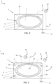
- an underwater storage tank of a working liquid 2 is generically identified with reference numeral 1.
- the underwater storage tank 1 comprises a flexible multilayer tank 3 which contains said working liquid 2.
- said flexible multilayer tank 3 is a tank referred to as a bladder.
- said underwater storage tank 1 comprises a pump 15 connected to said flexible tank 3 by means of at least one duct for withdrawing or reloading said working fluid 2.
- said duct comprises a metal flange in contact with said working fluid 2, connected to said flexible tank 3.
- sea water means any water of a body of water, such as e.g. an ocean, a sea, a lake, or a river.
- the flexible multilayer tank 3 comprises at least one internal electrical insulating layer 4, an external electrical insulating layer 6 and an intermediate electric conductive layer 5 sealed between the inner layer 4 and the outer layer 6.
- the internal electrical insulating layer 4 is in contact with the working fluid 2 and the external electrical insulating layer 6 is in contact with the sea water.
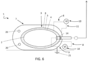
- the underwater storage tank 1 comprises at least a first electrical connection means 8 connected to the intermediate conductive layer 5.
- the first electrical connection means 8 is connectable to an electrical grounded measurement instrument 10 to assess the physical integrity of the flexible multilayer tank 3.
- the flexible multilayer tank 3 comprises further layers, e.g. adhesive layers, interposed between the intermediate layer 5 and the inner layer 4 and the outer layer 6, respectively.
- the electric conductive layer 5 has a first electric potential known under conditions of integrity of the flexible multilayer tank 3.
- said at least one measurement instrument 10 comprises a positive pole and a negative pole.
- the positive pole is electrically connectable to the intermediate electric conductive layer 5 and the negative pole is electrically connected to a grounding system 21.
- the intermediate electric conductive layer 5 is a layer which is seamlessly interposed between the internal electrical insulating layer 4 and the external electrical insulating layer 6.
- a loss of integrity of the external electrical insulating layer 6 places at least one portion of the intermediate electric conductive layer 5 in contact with the sea water, and therefore said at least one electrical measurement instrument 10 connected to a ground once connected to the first electrical connection means 8 may detect a variation of the passage of electric current, and therefore detect said loss of integrity of the flexible multilayer tank 3.
- the intermediate electric conductive layer 5 comprises a plurality of sectors 12 which are electrically insulated from one another.
- the intermediate electric conductive layer 5 may be a discontinuous layer which has a plurality of sectors 12 which are electrically insulated both peripherally from one another and with respect to the working liquid 2 in contact with the internal electrical insulating layer 4, and with respect to the sea water in contact with the external electrical insulating layer 6.
- the underwater storage tank 1 comprises a first electrical connection means 8 for each sector 12 of the plurality of electrically insulated sectors.
- each sector 12 of the plurality of sectors 12 is connected to a respective first electrical connection means 8.
- each respective first electrical connection means 8 is connectable to at least one electrical grounded measurement instrument 10 to assess the physical integrity of the flexible multilayer tank 3 at the corresponding sector 12 to which the respective first connection means 8 is connected.
- each sector 12 of the plurality of sectors 12 of the intermediate layer 5 is electrically connectable, by means of the respective first electrical connection means 8, to the positive pole of one or of a respective electrical measurement instrument 10, and such an electrical measurement instrument 10 in turn is electrically connected to a grounding system 21 with the negative pole thereof.
- a loss of integrity of the external electrical insulating layer 6 may be detected and spatially localized due to the fact that the intermediate electric conductive layer 5 comprises said plurality of sectors 12, in which each sector is electrically connectable to an electrical grounded measurement instrument 10 by means of a respective first electrical connection means 8.
- the working liquid 2 is a solution of conductive liquid or a mixture of conductive liquids.
- the underwater storage tank 1 comprises at least one electrode 14 in contact with the working liquid 2.
- the underwater storage tank comprises at least a second electrical connection means 9 connected to the second electrode 14.
- the second electrical connection means 9 is connectable to a measurement instrument 10 electrically connected with the intermediate conductive layer 5 to assess the physical integrity of the flexible tank 3.
- said at least one measurement instrument 10 comprises a positive electric terminal and a negative electric terminal.
- the positive electric terminal is electrically connected to the intermediate electric conductive layer 5 and the negative electric terminal is electrically connected to the conductive working liquid 2.
- said electrode 14 is, e.g. a flange, as shown in Figure 6 .
- a loss of integrity of the inner layer 4 of the flexible multilayer tank 3 puts the intermediate electric conductive layer 5 in direct electrical connection with the conductive working liquid 2, and therefore, a variation of the insulating resistance of the internal electrical insulating layer 4 may be detected, and accordingly said loss of integrity of the flexible multilayer tank 3 may be detected by means of said measurement instrument 10 connectable by means of said second electrical connection means 9 to said electrode 14 and electrically connected to said intermediate electric conductive layer 5.
- the detection of a loss of integrity of the external electrical insulating layer 6 by means of a grounded electrical measurement instrument 10 electrically connected to the intermediate electric conductive layer 5 in conjunction with the detection of a loss of integrity of the internal electrical insulating layer 4 by means of a further electrical measurement instrument 10 or the same measurement instrument 10 connected to the intermediate electric conductive layer 5 and electrically connected to electrode 14 advantageously allows also a possible dispersion of said conductive working liquid 2 to be detected in the marine environment.
- the underwater storage tank 1 comprises a rigid containment structure 7 in which the flexible multilayer tank 3 is contained.
- rigid structure 7 comprises at least one bathymetric compensation opening 20 for the passage of sea water capable of compensating for the variation of internal pressure of said flexible multilayer tank 3 due to a withdrawal of the working fluid 3.
- the underwater storage tank 1 comprises at least one grounding system 21 and at least one third electrical connection means 11 electrically connected to said grounding system 21.
- the third electrical connection means 11 is connectable to an electrical measurement instrument 10 electrically connected with said intermediate conductive layer 5 by means of said first electrical connection means 8 to assess the physical integrity of said flexible tank 3.
- the rigid structure 7 may be completely metal and grounded by means of the grounding system 21, or made partially of non-conductive material such as, for example a tank made of composite material (e.g. a resin reinforced with fiberglass) which has portions of conductive material which are integral with the non-conductive rigid structure and grounded by means of the grounding system 21.
- non-conductive material such as, for example a tank made of composite material (e.g. a resin reinforced with fiberglass) which has portions of conductive material which are integral with the non-conductive rigid structure and grounded by means of the grounding system 21.
- the at least a third electrical connection means 11 is grounded by means of the rigid structure connected to the grounding system 21.
- the internal electrical insulating layer 4 is made of a first material chemically compatible with the working liquid 2.
- said first material chemically compatible with the working liquid 2 is a fluorinated polymer.
- such a fluorinated polymer is a polymer of the family of fluorinated elastomers known with the acronym FKM according to the international abbreviation ISO 1629.
- such a fluorinated polymer may be one of the following polymers known commercially as Viton ® (DuPont), Dyneon ® (3M), Tecnoflon ® (Solvay), Dai-El ® (Daikin).
- said first material chemically compatible with the working liquid 2 is a rubber.
- such a rubber is an elastomeric rubber, which may be IIR (monomer isobutene-isoprene) or EPDM (monomer ethylene-propylene-diene) or SBR (monomer styrene-butadiene).
- IIR monomer isobutene-isoprene
- EPDM monomer ethylene-propylene-diene
- SBR monomer styrene-butadiene
- the external electrical insulating layer 6 is made of a second material chemically compatible with the sea water.
- the second material chemically compatible with the sea water is a synthetic rubber known with the abbreviation CSM (chlorosulphonated polyethylene) according to the international abbreviation ISO 1629, which is commercially known as Hypalon ® (DuPont Performance Elastomers), or a rubber made of IIR (monomer isobutene-isoprene) or EPDM (monomer ethylene-propylene-diene).
- the intermediate electric conductive layer 5 is a mechanical reinforcing layer.
- the intermediate layer 5 also acts as mechanical support for the flexible multilayer tank 3 and as outer protective element of the internal electrical insulating layer 4.
- the intermediate electric conductive layer 5 is a flexible metal sheet.
- said flexible sheet is a continuous sheet.
- said flexible sheet is a discontinuous sheet.
- said flexible metal sheet has a maximum thickness of 0.1 mm.
- said flexible metal sheet is made of aluminum.
- the intermediate electric conductive layer 5 is a conductive wire mesh.
- such a conductive wire mesh is a metal wire mesh or a conductive fiber wire mesh.
- said metal wire mesh is a copper wire mesh.
- said conductive fiber metal wire mesh is a mesh made at least of carbon fiber.
- the intermediate electric conductive layer 5 is made in the form of a fabric comprising at least one carbon fiber.
- the intermediate electric conductive layer 5 may consist only partially of electric conductive material; for example, it may be represented by a polyester fiber fabric alternated with conductive material fibers.
- the intermediate electric conductive layer 5 may consist of non-conductive base material, such as, e.g. polyester, which is made conductive through a specific treatment; in this regard, suitable treatments may include: spraying, electroless plating, sputter coating, plasma treatments, vacuum metallizing, polymerization in situ, chemical vapor deposition, textile coating/printing.
- the intermediate electric conductive layer 5 may consist of a polymer, such as e.g. nitrile butadiene rubber (NBR), loaded with carbon particles/fibers or an equivalent conductive material which gives the polymeric layer electro-conductive properties.
- NBR nitrile butadiene rubber
- the rigid containment structure 7 is a support and protective structure of the flexible multilayer tank 3, for example in the laying, working liquid 2 withdrawal and recovery steps.
- the rigid containment structure 7 is an anchoring structure of the flexible multilayer tank 3.
- the underwater storage tank 1 therefore is anchored to the seabed, or to a bed of a different body of water such as a lake, a river, or an artificial reservoir.
- the rigid structure 7 peripherally surrounds said flexible multilayer tank 3.
- an electrical measurement instrument 10 connected to the intermediate electric conductive layer 5 and connected to the grounding system 21 or electrode 14 detects a loss of integrity in any position of said leak of the flexible multilayer tank 3.
- the rigid structure 7 is made like a metal cage having at least one mesh structure and comprises a plurality of openings 20. Therefore, the sea water is free to come into contact with the flexible multilayer tank 3, avoiding any differences in pressure.
- the rigid structure 7 has a rigid box-like or cylindrical tank shape comprising at least one inlet path 20 to allow the inlet of sea water therein and therefore to come into contact with the flexible multilayer tank 3.
- the rigid structure 7 has a frame shape comprising cross members and peripheral uprights.
- said at least one measurement instrument 10 is any system capable of measuring and identifying a loss of electrical insulation.
- said at least one measurement instrument 10 e.g. a megohmmeter, or a multimeter which comprises a megohmmeter.
- said at least one measurement instrument 10 is positioned close to the rigid containment structure 7.
- said at least one measurement instrument 10 is integrated in a subsea electronic module or in a subsea control module 17 of known type with which said storage tank 1 is provided.
- each electrical connection means 8, 9, 11 is in the form of an underwater electrical connection cable.
- each electrical connection means 8, 9, 11 has a connector connected to a subsea electronic module or to a subsea control module 17 of known type with which the underwater storage tank 1 is provided.
- said at least one measurement instrument 10 is connectable to the respective connectors of the electrical connection means 8, 9, 11 in the subsea electronic module or in a subsea control module 17 of known type with which said storage tank 1 is provided.
- said at least one measurement instrument 10 is housed or integrated in an AUV (autonomous underwater vehicle) or an ROV (remotely operated vehicle).
- AUV autonomous underwater vehicle
- ROV remotely operated vehicle
- the underwater storage tank 1 comprises at least one visual inspection means, such as for example at least one camera. Thereby, the state of integrity of said storage tank 1 may be visually monitored.
- the present invention relates to an assessment system of the physical integrity of an underwater storage tank which comprises said underwater storage tank 1 described in the present description, and at least one electrical measurement instrument 10 described above, to assess the physical integrity of the flexible multilayer tank 3.
- said at least one electrical measurement instrument 10 is connectable and/or electrically connected at least to the intermediate electric conductive layer 5 of the flexible multilayer tank 3 and to one between an electrical grounding system 21 and said working liquid 2.
- the present invention describes a method for detecting a loss of physical integrity of an underwater storage tank 1 for a working liquid 2 by means of a detection system described above, in which said underwater storage tank 1 comprises a flexible multilayer tank 3 containing said working liquid 2, said flexible multilayer tank 3 being externally in contact with sea water, said flexible multilayer tank 3 comprising at least one internal electrical insulating layer 4 in contact with said working fluid 2, at least one external electrical insulating layer 6 in contact with sea water, at least one intermediate electric conductive layer 7 sealed between said at least one internal electrical insulating layer 4 and said at least one external electrical insulating layer 6, at least one first electrical connection means 8 connected to said intermediate conductive layer 5, said first electrical connection means 8 being electrically connectable and/or connected to said at least one electrical grounded measurement instrument 10 to assess the physical integrity of said flexible tank 3.
- Such a method comprises the following steps:
- the present invention relates to a further method for detecting a loss of physical integrity of an underwater storage tank 1 of a working liquid 2 by means of a detection system described above, in which said underwater storage tank 1 comprises a flexible multilayer tank 3 containing said working liquid 2, said flexible multilayer tank 3 being externally in contact with sea water, said flexible multilayer tank 3 comprising at least one internal electrical insulating layer 4 in contact with said working fluid 2, at least one external electrical insulating layer 6 in contact with sea water, at least one intermediate electric conductive layer 7 sealed between said at least one internal electrical insulating layer 4 and said at least one external electrical insulating layer 6, in which said intermediate electric conductive layer 5 comprises a plurality of sectors 12 electrically insulated therebetween and in which each sector 12 of said plurality of sectors 12 is connected to a respective first electrical connection means 8, each respective first electrical connection means 8 being connectable to said at least one electrical grounded measurement instrument 10 to assess the physical integrity of said flexible tank 3 at the corresponding sector 12 to which said respective first connection means 8 is connected.
- Such a method comprises the steps of:
- said underwater tank 1 comprises at least one electrode 14 in contact with said working liquid 2 and at least one second electrical connection means 9 connected to said electrode 14, said second electrical connection means 9 being electrically connectable and/or connected to said at least one measurement instrument 10 electrically connected to said intermediate conductive layer 5 to assess the physical integrity of said flexible tank 3, such methods comprise the further following steps:
- the underwater storage tank 1 comprises a flexible multilayer tank 3 having a shape of a cushion of the volume of 30 m3 and a rigid containment structure 7 grounded by means of a grounding system 21.
- the rigid structure 7 is a metal rigid structure in the shape of a box-like frame; it has uprights and cross members along the perimeter thereof and supports the flexible multilayer tank 3.
- the flexible multilayer tank 3 is filled with a solution containing a non-conductive organic solvent 2.
- the flexible multilayer tank 3 comprises an internal electrical insulating layer 4 consisting of an FKM membrane in contact with the organic solvent 2 and an external electrical insulating layer 6 consisting of a Hypalon ® rubber membrane in contact with the sea water.
- An intermediate electric conductive layer 5 consisting of a carbon fiber fabric is sealingly positioned in between the two membranes 4, 6.
- the underwater storage tank 1 comprises a first electrical connection means 8 connected to the carbon fiber fabric 5 and connected to a measurement instrument 10 in the form of a megohmmeter.
- the underwater storage tank 1 comprises a third electrical connection means 11 connected to said rigid structure 7 and connected to said measurement instrument in the form of a megohmmeter.
- the megohmmeter has a positive pole connected to the carbon fiber fabric 5 and a negative pole connected to the grounded rigid metal structure 7 which supports the flexible multilayer tank 3.
- the electrical insulation of the carbon fiber fabric 5 is compromised and megohmmeter 9 signals a reduction of the insulation resistance measured due to a passage of electrons and a subsequent reduction of the physical integrity of the flexible multilayer tank 3.
- a visual inspection may be scheduled to assess whether or not to recuperate the underwater storage tank 1 and replace it or make other provisions prior to a dispersion event of the working liquid 2 into the marine environment.
- the underwater storage tank 1 comprises a flexible multilayer tank 3 having a shape of a cushion and a bathymetrically compensated rigid containment structure 7 connected to a grounding system 21.
- the rigid structure 7 is in the form of a metal crate inside of which the flexible multilayer tank 3 is positioned.
- the metal crate 7 has circular openings 20 to allow the sea water to enter therein and externally surround the flexible multilayer tank 3.
- the flexible multilayer tank 3 is filled with an aqueous solution in which a polar oligomer 2 is dissolved, therefore solution 2 is conductive.
- the flexible multilayer tank 3 comprises an internal electrical insulating layer 4 consisting of an IIR rubber membrane in contact with the polar solution and an external electrical insulating layer 6 consisting of an IIR rubber membrane in contact with the sea water.
- An intermediate electric conductive layer 5 consisting of a carbon fiber fabric is sealingly positioned in between the two membranes 4, 6.
- the underwater storage tank 1 comprises a first electrical connection means 8 connected to said flexible multilayer tank 3 and a third connection means 11 connected to said metal crate 7, both connected to a first measurement instrument 10 in the form of a first megohmmeter; moreover, the underwater storage tank comprises a further first electrical connection measurement means 8 connected to said flexible multilayer tank 3 and a second electrical connection means 9 connected to an electrode 14 in contact with the working liquid 2, both connected to a second measurement instrument 10 in the form of a second megohmmeter.
- the first megohmmeter has a positive pole connected to the carbon fiber fabric 5 and a negative pole connected to the metal crate 7.
- the second megohmmeter has a positive pole connected to the carbon fiber fabric 5 and a negative pole connected to the polar solution 2 by means of electrode 14.
- the carbon fiber fabric 5 comes into contact with the sea water due, for example to a gap in the outer IIR layer 6, the electrical insulation of the carbon fiber fabric 5 is compromised and the first megohmmeter signals a passage of electrons and a subsequent reduction of the physical integrity of the flexible multilayer tank 3.
- the second megohmmeter signals a passage of electrons and a subsequent reduction of the physical integrity of the flexible multilayer tank 3.
- the underwater storage tank 1 comprises a flexible multilayer tank 3 having a shape of a cushion and a bathymetrically compensated rigid containment structure 7 connected to a grounding system 21.
- the rigid structure 7 is in the form of a reticular grid inside of which the flexible multilayer tank 3 is positioned.
- the flexible multilayer tank 3 is filled with a hydroalcoholic solution 2.
- the flexible multilayer tank 3 comprises an internal electrical insulating layer 4 consisting of an IIR rubber membrane in contact with the hydroalcoholic solution 2 and an external electrical insulating layer 6 consisting of an EPDM rubber membrane in contact with the sea water.
- An intermediate electric conductive layer 5 consisting of a thin aluminum film is sealingly positioned in between the two membranes 4, 5.
- the thin aluminum film 5 is divided into a plurality of separate sectors 12 which are electrically insulated from one another.
- the underwater storage tank 1 comprises a plurality of first electrical connection means 8 connected to said flexible multilayer tank 3 and a respective plurality of third electrical connection means 11 connected to the metal grid 7.
- Each pair of first electrical connection means 8 and third electrical connection means is connected to a respective measurement instrument 10 in the form of a megohmmeter, each connected with the positive pole thereof to a respective sector of the plurality of sectors 12 of the aluminum film 5 and connected with the negative pole thereof to the metal grid 7.
- the megohmmeter connected to such a sector 12 signals a passage of electrons and a subsequent reduction of the physical integrity of the flexible multilayer tank 3.
- the zone in which the integrity of the flexible tank 3 was reduced may be localized and an on-site repair may be scheduled.
- each measurement instrument 10 depicted could be the same measurement instrument 10 housed in or integrated with an autonomous or remotely controlled subsea vehicle which connects each time to a respective pair of first electrical connection means 8 and of third electrical connection means 11 to measure the electrical insulation of a corresponding sector 12.
- the underwater storage tank 1 comprises a flexible multilayer tank 3 having a cylindrical shape and a bathymetrically compensated rigid containment structure 7 connected to a grounding system 21.
- the rigid structure 7 is in the form of a cylindrical metal tank inside of which the flexible multilayer tank 3 is positioned.
- the cylindrical metal tank 7 has openings 20 to allow the sea water to enter therein and externally come into contact with the flexible multilayer tank 3.
- the flexible multilayer tank 3 is filled with a non-conductive organic solution 2.
- the flexible multilayer tank 3 comprises an internal electrical insulating layer 4 consisting of a fluorinated FKM membrane in contact with the organic solvent 2 and an external electrical insulating layer 6 consisting of an IIR rubber membrane in contact with the sea water.
- An intermediate electric conductive layer 5 consisting of a metal mesh made of copper wires is sealingly positioned in between the two membranes.
- the underwater storage tank 1 comprises a first electrical connection means 8 connected to the intermediate electric conductive layer 5 and a third electrical connection means 11 connected to the cylindrical metal tank 7, both connected to a measurement instrument 10 in the form of a megohmmeter.
- the megohmmeter has a positive pole connected to the copper mesh 5 and a negative pole connected to the rigid structure 7 inside of which the flexible multilayer tank 3 is positioned.
- the electrical insulation of the copper mesh 5 is compromised and the megohmmeter signals a loss of insulation due to a passage of electrons and a subsequent reduction of the physical integrity of the flexible multilayer tank 3.
- a visual inspection may be scheduled to assess whether or not to recuperate the underwater storage tank 1 and replace it or replace it on site.
- Metal sheet a first megohmmeter and a second megohmmeter
- an underwater storage tank 1 of a working liquid 2 positioned on a seabed is shown.
- the underwater storage tank 1 comprises a flexible multilayer tank 3 having a cylindrical shape and a bathymetrically compensated rigid containment structure 7 connected to a grounding system 21.
- the rigid structure 7 is in the form of a cylindrical metal tank inside of which the flexible multilayer tank 3 is positioned.
- the cylindrical metal tank 7 has circular openings 20 to allow the sea water to enter therein and externally surround the flexible multilayer tank 3.
- the flexible multilayer tank 3 is filled with an aqueous, electrically conductive sodium phosphate solution 2.
- the flexible multilayer tank 3 comprises an internal electrical insulating layer 4 consisting of an EPDM membrane in contact with the aqueous sodium phosphate solution 2 and an external electrical insulating layer 6 consisting of a Hypalon ® rubber membrane in contact with the sea water.
- An intermediate electric conductive layer 5 consisting of thin aluminum film (maximum thickness of 0.1 mm) is sealingly positioned in between the two membranes 4, 6.
- the underwater storage tank 1 comprises a first electrical connection means 8 connected to the thin aluminum film and a third electrical connection means 11 connected to the metal rigid structure 7, both connected to a first measurement instrument 10 in the form of a first megohmmeter, and the underwater storage tank 1 comprises a further first electrical connection means 8 connected to the thin aluminum sheet 5 and a second electrical connection means 9 connected to an electrode 14 (in the form of a flange), both connected to a second measurement instrument 10 in the form of a second megohmmeter.
- the first megohmmeter has a positive pole connected to the thin aluminum film 5 and a negative pole connected to the cylindrical metal tank 7.
- the second megohmmeter has a positive pole connected to the thin aluminum film 5 and a negative pole connected with the aqueous sodium phosphate solution 2 by means of the flange.
- the thin aluminum film 5 comes into contact with the sea water due, for example to a gap in the outer EPDM layer 6, the electrical insulation of the thin aluminum film 5 is compromised and the first megohmmeter signals a loss of insulation due to a passage of electrons and a subsequent reduction of the physical integrity of the flexible multilayer tank 3. If instead the thin aluminum film 5 comes into contact with the electrically conductive solution 2 due to a break of the inner Hypalon ® membrane 4, the second megohmmeter signals a loss of electrical insulation due to a passage of electrons and a subsequent reduction of the physical integrity of the flexible multilayer tank 3.
- both first megohmmeter and the second megohmmeter signal a passage of electrons, a possible gapping of the flexible multilayer tank 3 is detected and it is possible to intervene to recuperate the underwater storage tank 1 to limit possible dispersions of the electrically conductive solution into the marine environment.
Landscapes
- Engineering & Computer Science (AREA)
- Mechanical Engineering (AREA)
- Physics & Mathematics (AREA)
- General Physics & Mathematics (AREA)
- Business, Economics & Management (AREA)
- Emergency Management (AREA)
- Examining Or Testing Airtightness (AREA)
- Electrical Discharge Machining, Electrochemical Machining, And Combined Machining (AREA)
- Investigating Or Analyzing Materials By The Use Of Electric Means (AREA)
Claims (12)
- Réservoir de stockage sous-marin (1) pour liquide de travail (2) comprenant un réservoir multicouche souple (3) contenant ledit liquide de travail (2), ledit réservoir multicouche souple (3) étant en contact à l'extérieur avec de l'eau de mer,
caractérisé en ce queledit réservoir multicouche souple (3) comprend au moins une couche d'isolation électrique interne (4) en contact avec ledit fluide de travail (2), au moins une couche d'isolation électrique externe (6) en contact avec de l'eau de mer,au moins une couche conductrice électrique intermédiaire (5) rendue étanche entre ladite couche d'isolation électrique interne (4), au moins au nombre de une, et ladite couche d'isolation électrique externe (6), au moins au nombre de une,au moins un premier moyen de connexion électrique (8) connecté à ladite couche conductrice intermédiaire (5), ledit premier moyen de connexion électrique (8) pouvant être connecté à un instrument de mesure électrique mis à la terre (10) pour évaluer l'intégrité physique dudit réservoir multicouche souple (3). - Réservoir de stockage sous-marin (1) selon la revendication précédente, dans lequel ladite couche conductrice électrique intermédiaire (5) comprend une pluralité de secteurs (12) isolés électriquement entre eux, et dans lequel chaque secteur (12) de ladite pluralité de secteurs (12) est connecté à un premier moyen de connexion électrique (8) respectif, chaque premier moyen de connexion électrique (8) respectif pouvant être connecté à un instrument de mesure électrique mis à la terre (10) pour évaluer l'intégrité physique dudit réservoir multicouche souple (3) au niveau du secteur correspondant (12) auquel ledit premier moyen de connexion (8) respectif est connecté.
- Réservoir de stockage sous-marin (1) selon l'une quelconque des revendications précédentes, dans lequel ledit liquide de travail (2) est un liquide conducteur, et dans lequel ledit réservoir de stockage sous-marin (1) comprend au moins une électrode (14) en contact avec ledit liquide du travail (2), et au moins un deuxième moyen de connexion électrique (9) connecté à ladite électrode (14), ledit deuxième moyen de connexion électrique (9) pouvant être connecté à un instrument de mesure (10) connecté électriquement à ladite couche conductrice intermédiaire (5) pour évaluer l'intégrité physique dudit réservoir souple (3).
- Réservoir de stockage sous-marin (1) selon l'une quelconque des revendications précédentes, comprenant une structure de confinement rigide (7) dans laquelle ledit réservoir multicouche souple (3) est contenu, ladite structure rigide (7) comprenant au moins une ouverture de compensation bathymétrique (20) destinée au passage de l'eau de mer capable de compenser la variation de pression interne dudit réservoir multicouche souple (3) en raison d'un retrait du fluide de travail (3).
- Réservoir de stockage sous-marin (1) selon l'une quelconque des revendications précédentes, comprenant au moins un système de mise à la terre (21) et au moins un troisième moyen de connexion électrique (11) connecté électriquement audit système de mise à la terre (21), ledit troisième moyen de connexion électrique (11) pouvant être connecté à un instrument de mesure électrique (10) connecté électriquement à ladite couche conductrice intermédiaire (5) au moyen dudit premier moyen de connexion électrique (8) pour évaluer l'intégrité physique dudit réservoir souple (3).
- Réservoir de stockage sous-marin (1) selon l'une quelconque des revendications précédentes, dans lequel ladite couche d'isolation électrique interne (4) est faite d'un premier matériau qui est chimiquement compatible avec ledit liquide de travail (2).
- Réservoir de stockage sous-marin (1) selon l'une quelconque des revendications précédentes, dans lequel ladite couche d'isolation électrique externe (6) est faite d'un second matériau qui est chimiquement compatible avec ladite eau de mer.
- Réservoir de stockage sous-marin (1) selon l'une quelconque des revendications précédentes, dans lequel ladite couche conductrice électrique intermédiaire (5) est une toile métallique électriquement conductrice ou un tissu comprenant une fibre de carbone ou une toile métallique de fibre de carbone ou une feuille métallique souple.
- Système d'évaluation de l'intégrité physique d'un réservoir sous-marin comprenant un réservoir de stockage sous-marin (1) selon l'une quelconque des revendications précédentes 1 à 8, et au moins un instrument de mesure électrique (10) permettant d'évaluer l'intégrité physique dudit réservoir multicouche souple (3), ledit instrument de mesure électrique (10) pouvant être connecté et/ou étant connecté électriquement au moins à ladite couche conductrice électrique intermédiaire (5) dudit réservoir multicouche souple (3) et à un élément parmi un système de mise à la terre électrique (21) et ledit liquide de travail (2).
- Procédé de détection d'une perte d'intégrité physique d'un réservoir de stockage sous-marin (1) pour liquide de travail (2) au moyen d'un système de détection selon la revendication 9, dans lequel
ledit réservoir de stockage sous-marin (1) comprend un réservoir multicouche souple (3) contenant ledit liquide de travail (2), ledit réservoir multicouche souple (3) étant en contact à l'extérieur avec de l'eau de mer, ledit réservoir multicouche souple (3) comprenant au moins une couche d'isolation électrique interne (4) en contact avec ledit fluide de travail (2), au moins une couche d'isolation électrique externe (6) en contact avec de l'eau de mer, au moins une couche conductrice électrique intermédiaire (7) rendue étanche entre ladite couche d'isolation électrique interne (4), au moins au nombre de une, et ladite couche d'isolation électrique externe (6), au moins au nombre de une, au moins un premier moyen de connexion électrique (8) connecté à ladite couche conductrice intermédiaire (5), ledit premier moyen de connexion électrique (8) pouvant être électriquement connecté et/ou étant connecté audit instrument de mesure électrique mis à la terre (10), au moins au nombre de un, pour évaluer l'intégrité physique dudit réservoir souple (3), ledit procédé comprenant les étapes suivantes :- l'enregistrement d'au moins d'une valeur seuil de résistance d'isolement (Rse) de ladite couche d'isolation électrique externe (6) correspondant à une perte d'intégrité dudit réservoir multicouche souple (3),- la détection d'une valeur de résistance d'isolement actuelle (Re) de ladite couche d'isolation électrique externe (6),- la comparaison de ladite valeur de résistance d'isolement actuelle (Re) avec ladite valeur seuil de résistance d'isolement (Rse),- l'envoi d'un signal d'avertissement (Se) pour perte externe d'intégrité dudit réservoir sous-marin (1) si ladite valeur de résistance d'isolement actuelle (R) détectée est inférieure à ladite valeur seuil de résistance d'isolement (Rse). - Procédé de détection d'une perte d'intégrité physique d'un réservoir de stockage sous-marin (1) pour liquide de travail (2) au moyen d'un système de détection selon la revendication 9, dans lequel
ledit réservoir de stockage sous-marin (1) comprend un réservoir multicouche souple (3) contenant ledit liquide de travail (2), ledit réservoir multicouche souple (3) étant à l'extérieur en contact avec de l'eau de mer, ledit réservoir multicouche souple (3) comprenant au moins une couche d'isolation électrique interne (4) en contact avec ledit fluide de travail (2), au moins une couche d'isolation électrique externe (6) en contact avec de l'eau de mer, au moins une couche conductrice électrique intermédiaire (7) rendue étanche entre ladite couche d'isolation électrique interne (4), au moins au nombre de une, et ladite couche d'isolation électrique externe (6), au moins au nombre de une, dans lequel ladite couche conductrice électrique intermédiaire (5) comprend une pluralité de secteurs (12) isolés électriquement entre eux et dans lequel chaque secteur (12) de ladite pluralité de secteurs (12) est connecté à un premier moyen de connexion électrique (8) respectif, chaque premier moyen de connexion électrique (8) respectif pouvant être connecté audit instrument de mesure électrique mis à la terre (10), au moins au nombre de un, pour évaluer l'intégrité physique dudit réservoir souple (3) au niveau du secteur correspondant (12) auquel ledit premier moyen de connexion (8) respectif est connecté, ledit procédé comprenant les étapes suivantes :- l'enregistrement d'au moins d'une valeur seuil de résistance d'isolement (Rse) de ladite couche d'isolation électrique externe (6) correspondant à une perte d'intégrité dudit réservoir multicouche souple (3),- la détection d'une valeur de résistance d'isolement de secteur actuelle (Rsci) de ladite couche d'isolation électrique externe (6) au niveau de chaque secteur (12) de ladite pluralité de secteurs (12),- la comparaison de chaque valeur de résistance d'isolement de secteur actuelle (Rsci) détectée avec ladite valeur seuil de résistance d'isolement (Rse) de ladite couche d'isolation électrique externe (6),- l'envoi d'un signal d'avertissement (Sel) pour une perte externe localisée d'intégrité dudit réservoir sous-marin (1) pour chaque valeur de résistance d'isolement de secteur actuelle (Rsci) détectée qui est inférieure à ladite valeur seuil de résistance d'isolement (Rs). - Procédé selon la revendication précédente 10 ou 11, dans lequel ledit liquide de travail (2) est un liquide conducteur, et dans lequel ledit réservoir sous-marin (1) comprend au moins une électrode (14) en contact avec ledit liquide du travail (2), et au moins un deuxième moyen de connexion électrique (9) connecté à ladite électrode (14), ledit deuxième moyen de connexion électrique (9) pouvant être électriquement connecté audit instrument de mesure (10), au moins au nombre de un, connecté électriquement à ladite couche conductrice intermédiaire (5) pour évaluer l'intégrité physique dudit réservoir souple (3), ledit procédé comprenant les étapes suivantes :- l'enregistrement d'au moins d'une valeur seuil de résistance d'isolement (Rsi) de ladite couche d'isolation électrique interne (4) correspondant à une perte d'intégrité dudit réservoir multicouche souple (3),- la détection d'une valeur de résistance d'isolement actuelle (Ri) de ladite couche d'isolation électrique interne (4),- la comparaison de ladite valeur de résistance d'isolement actuelle (Ri) avec ladite valeur seuil de résistance d'isolement (Rsi),- l'envoi d'un signal d'avertissement (Si) pour une perte interne d'intégrité dudit réservoir sous-marin (1) si ladite valeur de résistance d'isolement actuelle (Ri) détectée est inférieure à la valeur seuil de résistance d'isolement (Rsi).
Applications Claiming Priority (2)
| Application Number | Priority Date | Filing Date | Title |
|---|---|---|---|
| IT102019000014271A IT201900014271A1 (it) | 2019-08-07 | 2019-08-07 | Serbatoio di stoccaggio subacqueo |
| PCT/IB2020/057334 WO2021024166A1 (fr) | 2019-08-07 | 2020-08-03 | Réservoir de stockage sous-marin, système d'évaluation de l'intégrité physique d'un réservoir sous-marin, procédé de détection d'une perte d'intégrité physique d'un réservoir de stockage sous-marin |
Publications (2)
| Publication Number | Publication Date |
|---|---|
| EP3980353A1 EP3980353A1 (fr) | 2022-04-13 |
| EP3980353B1 true EP3980353B1 (fr) | 2024-05-29 |
Family
ID=68988198
Family Applications (1)
| Application Number | Title | Priority Date | Filing Date |
|---|---|---|---|
| EP20764453.5A Active EP3980353B1 (fr) | 2019-08-07 | 2020-08-03 | Réservoir de stockage sous-marin, système d'évaluation de l'intégrité physique d'un réservoir sous-marin, procédé de détection d'une perte d'intégrité physique d'un réservoir de stockage sous-marin |
Country Status (5)
| Country | Link |
|---|---|
| US (1) | US11802902B2 (fr) |
| EP (1) | EP3980353B1 (fr) |
| BR (1) | BR112022001933A2 (fr) |
| IT (1) | IT201900014271A1 (fr) |
| WO (1) | WO2021024166A1 (fr) |
Family Cites Families (12)
| Publication number | Priority date | Publication date | Assignee | Title |
|---|---|---|---|---|
| DE9311620U1 (de) * | 1993-08-04 | 1993-10-07 | Sigri Great Lakes Carbon Gmbh, 65203 Wiesbaden | Auf Undichtigkeiten überprüfbare Auskleidungen auf der Basis von Gummi |
| US5553734A (en) * | 1994-08-31 | 1996-09-10 | Sharp; Bruce R. | Double walled storage tank systems with enhanced wall integrity |
| DE10302308B3 (de) * | 2003-01-22 | 2004-03-18 | InfraServ GmbH & Co. Höchst KG | Vorrichtung mit Auskleidung und deren Verwendung |
| EP1999446A4 (fr) * | 2006-03-22 | 2011-12-14 | Atmi Packaging Inc | Appareil et méthodes de détection de fuite dans des poches pour biotraitement |
| BRPI0712033B1 (pt) * | 2006-05-18 | 2018-01-23 | Mauser-Werke Gmbh | Recipiente de plástico de múltiplas camadas e método para produzir um recipiente de plástico de múltiplas camadas |
| US20090188211A1 (en) * | 2008-01-25 | 2009-07-30 | Xcellerex, Inc. | Bag wrinkle remover, leak detection systems, and electromagnetic agitation for liquid containment systems |
| US9775223B2 (en) * | 2013-02-28 | 2017-09-26 | Dan Steinberg | Composite structure with exposed conductive fiber for static dissipation, and method for making same |
| US10788271B2 (en) * | 2013-06-28 | 2020-09-29 | Ecovat Ip B.V. | Underground thermal energy storage |
| DE102013012759A1 (de) * | 2013-07-31 | 2015-02-05 | Sartorius Stedim Biotech Gmbh | Temperiervorrichtung; Verwendung und Anordnung |
| NO339211B1 (en) * | 2015-01-22 | 2016-11-14 | Kongsberg Oil & Gas Tech As | Storage system and flexible bag element for storing a fluid |
| US9656801B2 (en) | 2015-05-05 | 2017-05-23 | Safe Marine Transfer, LLC | Underwater storage tank and fill control mechanism |
| US11186433B2 (en) * | 2019-09-19 | 2021-11-30 | Robin Berg | Underground storage tank |
-
2019
- 2019-08-07 IT IT102019000014271A patent/IT201900014271A1/it unknown
-
2020
- 2020-08-03 US US17/632,797 patent/US11802902B2/en active Active
- 2020-08-03 BR BR112022001933A patent/BR112022001933A2/pt active IP Right Grant
- 2020-08-03 EP EP20764453.5A patent/EP3980353B1/fr active Active
- 2020-08-03 WO PCT/IB2020/057334 patent/WO2021024166A1/fr not_active Ceased
Also Published As
| Publication number | Publication date |
|---|---|
| IT201900014271A1 (it) | 2021-02-07 |
| US20230023109A1 (en) | 2023-01-26 |
| EP3980353A1 (fr) | 2022-04-13 |
| BR112022001933A2 (pt) | 2022-05-03 |
| US11802902B2 (en) | 2023-10-31 |
| WO2021024166A1 (fr) | 2021-02-11 |
Similar Documents
| Publication | Publication Date | Title |
|---|---|---|
| US9354135B2 (en) | Oil leak detection device | |
| US5341128A (en) | Sensor element for detection of hydrocarbons | |
| US9022123B2 (en) | Scuttle for the monitoring and inspection of a flexible riser | |
| US10663422B2 (en) | Apparatus and method for detecting defects within a flexible pipe | |
| EP0122730A1 (fr) | Elément sensible à excitation autonome | |
| EP3980353B1 (fr) | Réservoir de stockage sous-marin, système d'évaluation de l'intégrité physique d'un réservoir sous-marin, procédé de détection d'une perte d'intégrité physique d'un réservoir de stockage sous-marin | |
| EP3333562A2 (fr) | Détection à distance de dommages d'isolation sur des tubes ou tuyaux isolés | |
| US20110210857A1 (en) | Sensor unit for checking of monitoring areas of double-walled containers or double-walled pipelines, or double-walled vessels | |
| CN104565670A (zh) | 用于碳氢化合物管道的柔性接头、检测该接头中泄漏的方法及用于检测该接头中碳氢化合物泄漏的系统 | |
| CN208856235U (zh) | 一种双层油罐测漏传感器 | |
| US4771246A (en) | Method for determining the location of a leak in a pond liner formed of electrically insulating material | |
| CN111254443B (zh) | 一种海水管路杂散电流检测与控制装置和方法 | |
| OA20649A (en) | Underwater storage tank, system of assessing the physical integrity of an underwater tank, method for detecting a loss of physical integrity of an underwater storage tank. | |
| JP4747834B2 (ja) | マリンホースの流体漏れ検知システム | |
| US20190072479A1 (en) | Corrosion indicator for use with a piping system, and a piping system using the corrosion indicator | |
| US4143540A (en) | Method of preventing corrosion of joints of steel structures submerged in corrosive media | |
| CN108613019B (zh) | 双层管道测漏装置 | |
| US7556847B2 (en) | Underground reservoir for storing liquid products and a process for manufacturing an underground reservoir | |
| KR20160031759A (ko) | 폴리우레탄 폼을 이용한 테이프형 가스 감지 센서 | |
| KR102084721B1 (ko) | 정전용량형 누설 감지 센서 | |
| CN108584201A (zh) | 一种双层油罐测漏传感器 | |
| WO2007100313A2 (fr) | Ensemble de capteur de hors-bord en polymere composite a compensation de pression | |
| CN109488889A (zh) | 在役金属管道绝缘内衬层状况的在线检测方法 | |
| JPH1172408A (ja) | 漏液検出器,それを用いた漏液検出装置,及びそれを用いた漏液検出方法 | |
| KR101447988B1 (ko) | 방폭 누유 감지장치 |
Legal Events
| Date | Code | Title | Description |
|---|---|---|---|
| STAA | Information on the status of an ep patent application or granted ep patent |
Free format text: STATUS: UNKNOWN |
|
| STAA | Information on the status of an ep patent application or granted ep patent |
Free format text: STATUS: THE INTERNATIONAL PUBLICATION HAS BEEN MADE |
|
| PUAI | Public reference made under article 153(3) epc to a published international application that has entered the european phase |
Free format text: ORIGINAL CODE: 0009012 |
|
| STAA | Information on the status of an ep patent application or granted ep patent |
Free format text: STATUS: REQUEST FOR EXAMINATION WAS MADE |
|
| 17P | Request for examination filed |
Effective date: 20220105 |
|
| AK | Designated contracting states |
Kind code of ref document: A1 Designated state(s): AL AT BE BG CH CY CZ DE DK EE ES FI FR GB GR HR HU IE IS IT LI LT LU LV MC MK MT NL NO PL PT RO RS SE SI SK SM TR |
|
| DAV | Request for validation of the european patent (deleted) | ||
| DAX | Request for extension of the european patent (deleted) | ||
| RAP3 | Party data changed (applicant data changed or rights of an application transferred) |
Owner name: SAIPEM S.P.A. |
|
| RIN1 | Information on inventor provided before grant (corrected) |
Inventor name: ALBANI, YVAN Inventor name: MATTERAZZO, SANDRO |
|
| P01 | Opt-out of the competence of the unified patent court (upc) registered |
Effective date: 20230728 |
|
| REG | Reference to a national code |
Ref country code: DE Ref legal event code: R079 Free format text: PREVIOUS MAIN CLASS: B65D0088160000 Ipc: B65D0090040000 Ref document number: 602020031679 Country of ref document: DE |
|
| GRAP | Despatch of communication of intention to grant a patent |
Free format text: ORIGINAL CODE: EPIDOSNIGR1 |
|
| STAA | Information on the status of an ep patent application or granted ep patent |
Free format text: STATUS: GRANT OF PATENT IS INTENDED |
|
| RIC1 | Information provided on ipc code assigned before grant |
Ipc: B65D 90/513 20190101ALI20240105BHEP Ipc: B65D 88/78 20060101ALI20240105BHEP Ipc: B65D 90/04 20060101AFI20240105BHEP |
|
| INTG | Intention to grant announced |
Effective date: 20240124 |
|
| GRAS | Grant fee paid |
Free format text: ORIGINAL CODE: EPIDOSNIGR3 |
|
| GRAA | (expected) grant |
Free format text: ORIGINAL CODE: 0009210 |
|
| STAA | Information on the status of an ep patent application or granted ep patent |
Free format text: STATUS: THE PATENT HAS BEEN GRANTED |
|
| AK | Designated contracting states |
Kind code of ref document: B1 Designated state(s): AL AT BE BG CH CY CZ DE DK EE ES FI FR GB GR HR HU IE IS IT LI LT LU LV MC MK MT NL NO PL PT RO RS SE SI SK SM TR |
|
| REG | Reference to a national code |
Ref country code: CH Ref legal event code: EP |
|
| REG | Reference to a national code |
Ref country code: IE Ref legal event code: FG4D |
|
| REG | Reference to a national code |
Ref country code: DE Ref legal event code: R096 Ref document number: 602020031679 Country of ref document: DE |
|
| REG | Reference to a national code |
Ref country code: NL Ref legal event code: FP |
|
| REG | Reference to a national code |
Ref country code: LT Ref legal event code: MG9D |
|
| PG25 | Lapsed in a contracting state [announced via postgrant information from national office to epo] |
Ref country code: IS Free format text: LAPSE BECAUSE OF FAILURE TO SUBMIT A TRANSLATION OF THE DESCRIPTION OR TO PAY THE FEE WITHIN THE PRESCRIBED TIME-LIMIT Effective date: 20240929 |
|
| PG25 | Lapsed in a contracting state [announced via postgrant information from national office to epo] |
Ref country code: BG Free format text: LAPSE BECAUSE OF FAILURE TO SUBMIT A TRANSLATION OF THE DESCRIPTION OR TO PAY THE FEE WITHIN THE PRESCRIBED TIME-LIMIT Effective date: 20240529 |
|
| PG25 | Lapsed in a contracting state [announced via postgrant information from national office to epo] |
Ref country code: HR Free format text: LAPSE BECAUSE OF FAILURE TO SUBMIT A TRANSLATION OF THE DESCRIPTION OR TO PAY THE FEE WITHIN THE PRESCRIBED TIME-LIMIT Effective date: 20240529 Ref country code: FI Free format text: LAPSE BECAUSE OF FAILURE TO SUBMIT A TRANSLATION OF THE DESCRIPTION OR TO PAY THE FEE WITHIN THE PRESCRIBED TIME-LIMIT Effective date: 20240529 |
|
| PG25 | Lapsed in a contracting state [announced via postgrant information from national office to epo] |
Ref country code: GR Free format text: LAPSE BECAUSE OF FAILURE TO SUBMIT A TRANSLATION OF THE DESCRIPTION OR TO PAY THE FEE WITHIN THE PRESCRIBED TIME-LIMIT Effective date: 20240830 |
|
| REG | Reference to a national code |
Ref country code: AT Ref legal event code: MK05 Ref document number: 1690463 Country of ref document: AT Kind code of ref document: T Effective date: 20240529 |
|
| PG25 | Lapsed in a contracting state [announced via postgrant information from national office to epo] |
Ref country code: ES Free format text: LAPSE BECAUSE OF FAILURE TO SUBMIT A TRANSLATION OF THE DESCRIPTION OR TO PAY THE FEE WITHIN THE PRESCRIBED TIME-LIMIT Effective date: 20240529 |
|
| PG25 | Lapsed in a contracting state [announced via postgrant information from national office to epo] |
Ref country code: AT Free format text: LAPSE BECAUSE OF FAILURE TO SUBMIT A TRANSLATION OF THE DESCRIPTION OR TO PAY THE FEE WITHIN THE PRESCRIBED TIME-LIMIT Effective date: 20240529 |
|
| PG25 | Lapsed in a contracting state [announced via postgrant information from national office to epo] |
Ref country code: PL Free format text: LAPSE BECAUSE OF FAILURE TO SUBMIT A TRANSLATION OF THE DESCRIPTION OR TO PAY THE FEE WITHIN THE PRESCRIBED TIME-LIMIT Effective date: 20240529 |
|
| PG25 | Lapsed in a contracting state [announced via postgrant information from national office to epo] |
Ref country code: LV Free format text: LAPSE BECAUSE OF FAILURE TO SUBMIT A TRANSLATION OF THE DESCRIPTION OR TO PAY THE FEE WITHIN THE PRESCRIBED TIME-LIMIT Effective date: 20240529 |
|
| PG25 | Lapsed in a contracting state [announced via postgrant information from national office to epo] |
Ref country code: PL Free format text: LAPSE BECAUSE OF FAILURE TO SUBMIT A TRANSLATION OF THE DESCRIPTION OR TO PAY THE FEE WITHIN THE PRESCRIBED TIME-LIMIT Effective date: 20240529 Ref country code: LV Free format text: LAPSE BECAUSE OF FAILURE TO SUBMIT A TRANSLATION OF THE DESCRIPTION OR TO PAY THE FEE WITHIN THE PRESCRIBED TIME-LIMIT Effective date: 20240529 Ref country code: IS Free format text: LAPSE BECAUSE OF FAILURE TO SUBMIT A TRANSLATION OF THE DESCRIPTION OR TO PAY THE FEE WITHIN THE PRESCRIBED TIME-LIMIT Effective date: 20240929 Ref country code: HR Free format text: LAPSE BECAUSE OF FAILURE TO SUBMIT A TRANSLATION OF THE DESCRIPTION OR TO PAY THE FEE WITHIN THE PRESCRIBED TIME-LIMIT Effective date: 20240529 Ref country code: GR Free format text: LAPSE BECAUSE OF FAILURE TO SUBMIT A TRANSLATION OF THE DESCRIPTION OR TO PAY THE FEE WITHIN THE PRESCRIBED TIME-LIMIT Effective date: 20240830 Ref country code: FI Free format text: LAPSE BECAUSE OF FAILURE TO SUBMIT A TRANSLATION OF THE DESCRIPTION OR TO PAY THE FEE WITHIN THE PRESCRIBED TIME-LIMIT Effective date: 20240529 Ref country code: ES Free format text: LAPSE BECAUSE OF FAILURE TO SUBMIT A TRANSLATION OF THE DESCRIPTION OR TO PAY THE FEE WITHIN THE PRESCRIBED TIME-LIMIT Effective date: 20240529 Ref country code: BG Free format text: LAPSE BECAUSE OF FAILURE TO SUBMIT A TRANSLATION OF THE DESCRIPTION OR TO PAY THE FEE WITHIN THE PRESCRIBED TIME-LIMIT Effective date: 20240529 Ref country code: AT Free format text: LAPSE BECAUSE OF FAILURE TO SUBMIT A TRANSLATION OF THE DESCRIPTION OR TO PAY THE FEE WITHIN THE PRESCRIBED TIME-LIMIT Effective date: 20240529 Ref country code: RS Free format text: LAPSE BECAUSE OF FAILURE TO SUBMIT A TRANSLATION OF THE DESCRIPTION OR TO PAY THE FEE WITHIN THE PRESCRIBED TIME-LIMIT Effective date: 20240829 |
|
| PG25 | Lapsed in a contracting state [announced via postgrant information from national office to epo] |
Ref country code: DK Free format text: LAPSE BECAUSE OF FAILURE TO SUBMIT A TRANSLATION OF THE DESCRIPTION OR TO PAY THE FEE WITHIN THE PRESCRIBED TIME-LIMIT Effective date: 20240529 |
|
| PG25 | Lapsed in a contracting state [announced via postgrant information from national office to epo] |
Ref country code: EE Free format text: LAPSE BECAUSE OF FAILURE TO SUBMIT A TRANSLATION OF THE DESCRIPTION OR TO PAY THE FEE WITHIN THE PRESCRIBED TIME-LIMIT Effective date: 20240529 |
|
| PG25 | Lapsed in a contracting state [announced via postgrant information from national office to epo] |
Ref country code: CZ Free format text: LAPSE BECAUSE OF FAILURE TO SUBMIT A TRANSLATION OF THE DESCRIPTION OR TO PAY THE FEE WITHIN THE PRESCRIBED TIME-LIMIT Effective date: 20240529 |
|
| PG25 | Lapsed in a contracting state [announced via postgrant information from national office to epo] |
Ref country code: SK Free format text: LAPSE BECAUSE OF FAILURE TO SUBMIT A TRANSLATION OF THE DESCRIPTION OR TO PAY THE FEE WITHIN THE PRESCRIBED TIME-LIMIT Effective date: 20240529 Ref country code: RO Free format text: LAPSE BECAUSE OF FAILURE TO SUBMIT A TRANSLATION OF THE DESCRIPTION OR TO PAY THE FEE WITHIN THE PRESCRIBED TIME-LIMIT Effective date: 20240529 |
|
| PG25 | Lapsed in a contracting state [announced via postgrant information from national office to epo] |
Ref country code: SM Free format text: LAPSE BECAUSE OF FAILURE TO SUBMIT A TRANSLATION OF THE DESCRIPTION OR TO PAY THE FEE WITHIN THE PRESCRIBED TIME-LIMIT Effective date: 20240529 |
|
| PG25 | Lapsed in a contracting state [announced via postgrant information from national office to epo] |
Ref country code: SM Free format text: LAPSE BECAUSE OF FAILURE TO SUBMIT A TRANSLATION OF THE DESCRIPTION OR TO PAY THE FEE WITHIN THE PRESCRIBED TIME-LIMIT Effective date: 20240529 Ref country code: SK Free format text: LAPSE BECAUSE OF FAILURE TO SUBMIT A TRANSLATION OF THE DESCRIPTION OR TO PAY THE FEE WITHIN THE PRESCRIBED TIME-LIMIT Effective date: 20240529 Ref country code: RO Free format text: LAPSE BECAUSE OF FAILURE TO SUBMIT A TRANSLATION OF THE DESCRIPTION OR TO PAY THE FEE WITHIN THE PRESCRIBED TIME-LIMIT Effective date: 20240529 Ref country code: EE Free format text: LAPSE BECAUSE OF FAILURE TO SUBMIT A TRANSLATION OF THE DESCRIPTION OR TO PAY THE FEE WITHIN THE PRESCRIBED TIME-LIMIT Effective date: 20240529 Ref country code: DK Free format text: LAPSE BECAUSE OF FAILURE TO SUBMIT A TRANSLATION OF THE DESCRIPTION OR TO PAY THE FEE WITHIN THE PRESCRIBED TIME-LIMIT Effective date: 20240529 Ref country code: CZ Free format text: LAPSE BECAUSE OF FAILURE TO SUBMIT A TRANSLATION OF THE DESCRIPTION OR TO PAY THE FEE WITHIN THE PRESCRIBED TIME-LIMIT Effective date: 20240529 |
|
| REG | Reference to a national code |
Ref country code: DE Ref legal event code: R119 Ref document number: 602020031679 Country of ref document: DE |
|
| REG | Reference to a national code |
Ref country code: CH Ref legal event code: PL |
|
| PLBE | No opposition filed within time limit |
Free format text: ORIGINAL CODE: 0009261 |
|
| STAA | Information on the status of an ep patent application or granted ep patent |
Free format text: STATUS: NO OPPOSITION FILED WITHIN TIME LIMIT |
|
| PG25 | Lapsed in a contracting state [announced via postgrant information from national office to epo] |
Ref country code: LU Free format text: LAPSE BECAUSE OF NON-PAYMENT OF DUE FEES Effective date: 20240803 |
|
| PG25 | Lapsed in a contracting state [announced via postgrant information from national office to epo] |
Ref country code: SI Free format text: LAPSE BECAUSE OF FAILURE TO SUBMIT A TRANSLATION OF THE DESCRIPTION OR TO PAY THE FEE WITHIN THE PRESCRIBED TIME-LIMIT Effective date: 20240529 Ref country code: MC Free format text: LAPSE BECAUSE OF FAILURE TO SUBMIT A TRANSLATION OF THE DESCRIPTION OR TO PAY THE FEE WITHIN THE PRESCRIBED TIME-LIMIT Effective date: 20240529 Ref country code: CH Free format text: LAPSE BECAUSE OF NON-PAYMENT OF DUE FEES Effective date: 20240831 |
|
| 26N | No opposition filed |
Effective date: 20250303 |
|
| REG | Reference to a national code |
Ref country code: BE Ref legal event code: MM Effective date: 20240831 |
|
| PG25 | Lapsed in a contracting state [announced via postgrant information from national office to epo] |
Ref country code: DE Free format text: LAPSE BECAUSE OF NON-PAYMENT OF DUE FEES Effective date: 20250301 |
|
| PG25 | Lapsed in a contracting state [announced via postgrant information from national office to epo] |
Ref country code: BE Free format text: LAPSE BECAUSE OF NON-PAYMENT OF DUE FEES Effective date: 20240831 |
|
| PG25 | Lapsed in a contracting state [announced via postgrant information from national office to epo] |
Ref country code: IE Free format text: LAPSE BECAUSE OF NON-PAYMENT OF DUE FEES Effective date: 20240803 |
|
| PG25 | Lapsed in a contracting state [announced via postgrant information from national office to epo] |
Ref country code: SE Free format text: LAPSE BECAUSE OF FAILURE TO SUBMIT A TRANSLATION OF THE DESCRIPTION OR TO PAY THE FEE WITHIN THE PRESCRIBED TIME-LIMIT Effective date: 20240529 |
|
| PGFP | Annual fee paid to national office [announced via postgrant information from national office to epo] |
Ref country code: NL Payment date: 20250825 Year of fee payment: 6 |
|
| PGFP | Annual fee paid to national office [announced via postgrant information from national office to epo] |
Ref country code: NO Payment date: 20250819 Year of fee payment: 6 |
|
| PGFP | Annual fee paid to national office [announced via postgrant information from national office to epo] |
Ref country code: IT Payment date: 20250825 Year of fee payment: 6 |
|
| PGFP | Annual fee paid to national office [announced via postgrant information from national office to epo] |
Ref country code: GB Payment date: 20250826 Year of fee payment: 6 |
|
| PGFP | Annual fee paid to national office [announced via postgrant information from national office to epo] |
Ref country code: FR Payment date: 20250825 Year of fee payment: 6 |
|
| PG25 | Lapsed in a contracting state [announced via postgrant information from national office to epo] |
Ref country code: PT Free format text: LAPSE BECAUSE OF NON-PAYMENT OF DUE FEES Effective date: 20240529 |
|
| PG25 | Lapsed in a contracting state [announced via postgrant information from national office to epo] |
Ref country code: CY Free format text: LAPSE BECAUSE OF FAILURE TO SUBMIT A TRANSLATION OF THE DESCRIPTION OR TO PAY THE FEE WITHIN THE PRESCRIBED TIME-LIMIT; INVALID AB INITIO Effective date: 20200803 |
|
| PG25 | Lapsed in a contracting state [announced via postgrant information from national office to epo] |
Ref country code: HU Free format text: LAPSE BECAUSE OF FAILURE TO SUBMIT A TRANSLATION OF THE DESCRIPTION OR TO PAY THE FEE WITHIN THE PRESCRIBED TIME-LIMIT; INVALID AB INITIO Effective date: 20200803 |