EP3980624B1 - Umlaufbohrung in einem geschlossenen loch mit kontinuierlicher bohrlochüberwachung - Google Patents
Umlaufbohrung in einem geschlossenen loch mit kontinuierlicher bohrlochüberwachung Download PDFInfo
- Publication number
- EP3980624B1 EP3980624B1 EP20736806.9A EP20736806A EP3980624B1 EP 3980624 B1 EP3980624 B1 EP 3980624B1 EP 20736806 A EP20736806 A EP 20736806A EP 3980624 B1 EP3980624 B1 EP 3980624B1
- Authority
- EP
- European Patent Office
- Prior art keywords
- annulus
- drilling
- fluid
- wellbore
- mud cap
- Prior art date
- Legal status (The legal status is an assumption and is not a legal conclusion. Google has not performed a legal analysis and makes no representation as to the accuracy of the status listed.)
- Active
Links
Images




Classifications
-
- E—FIXED CONSTRUCTIONS
- E21—EARTH OR ROCK DRILLING; MINING
- E21B—EARTH OR ROCK DRILLING; OBTAINING OIL, GAS, WATER, SOLUBLE OR MELTABLE MATERIALS OR A SLURRY OF MINERALS FROM WELLS
- E21B21/00—Methods or apparatus for flushing boreholes, e.g. by use of exhaust air from motor
- E21B21/003—Means for stopping loss of drilling fluid
-
- E—FIXED CONSTRUCTIONS
- E21—EARTH OR ROCK DRILLING; MINING
- E21B—EARTH OR ROCK DRILLING; OBTAINING OIL, GAS, WATER, SOLUBLE OR MELTABLE MATERIALS OR A SLURRY OF MINERALS FROM WELLS
- E21B21/00—Methods or apparatus for flushing boreholes, e.g. by use of exhaust air from motor
- E21B21/08—Controlling or monitoring pressure or flow of drilling fluid, e.g. automatic filling of boreholes, automatic control of bottom pressure
-
- E—FIXED CONSTRUCTIONS
- E21—EARTH OR ROCK DRILLING; MINING
- E21B—EARTH OR ROCK DRILLING; OBTAINING OIL, GAS, WATER, SOLUBLE OR MELTABLE MATERIALS OR A SLURRY OF MINERALS FROM WELLS
- E21B44/00—Automatic control systems specially adapted for drilling operations, i.e. self-operating systems which function to carry out or modify a drilling operation without intervention of a human operator, e.g. computer-controlled drilling systems; Systems specially adapted for monitoring a plurality of drilling variables or conditions
Definitions
- drilling fluid is pumped down a drilling string, and returns are brought to the surface via the annulus of the borehole.
- the hydrostatic column in the annulus is controlled to handle fluid losses to the formation and to handle fluid influxes from the formation.
- Some reservoirs are located in carbonate formations, which are severely fractured with natural fractures, karsts, vugs, or caves. These carbonate reservoirs make up about 40% of all global reservoirs and make up approximately 70% of worldwide oil and gas reserves. Due to their prevalence, operators seek ways to drill to target depths in these naturally-fractured carbonate formations. Unfortunately, well control can be complicated when drilling in these carbonate formations because the fractures in the formations can cause severe loss of circulation followed by fluid influx.
- mud-cap drilling MCD
- PMCD Pressurized Mud Cap Drilling
- CHCD Closed Hole Circulation Drilling
- FMCD Floating Mud Cap Drilling
- Pressurized Mud Cap Drilling is a drilling technique used to drill without returns.
- An example implementation of Pressurized Mud Cap Drilling (PMCD) is disclosed in U.S. Pat. 7,237,623 .
- Floating Mud Cap Drilling is another drilling technique used to drill without returns. Sacrificial fluid is continuously pumped down the drillstring and the annulus to prevent formation fluid from migrating to the surface. Another document describing PMCD is e.g.
- a rotating control device In pressurized mud cap drilling, a rotating control device is used while drilling the wellbore and pumping a sacrificial fluid (e.g., water) down the drillpipe. At the same time, a pressurized mud-cap of weighted oil-based mud (OBM) is kept in the annulus to control possible fluid influx.
- a sacrificial fluid e.g., water
- mud cap drilling allows everything pumped into the wellbore along with drilling cuttings to be injected into the open-hole formation, while a fluid column of a Light Annular Mud (LAM) cap is maintained above the open-hole formation. Additional fluid can be periodically added into the annulus to control the surface back pressure within the operating limits of a rotating control device and/or a riser of the drilling system. In this way, the mud cap maintained in the annulus of the wellbore during drilling can stabilize the borehole and control the well.
- LAM Light Annular Mud
- FIG. 1 illustrates a wellbore 10 being drilled using pressurized mud cap drilling according to the prior art.
- a drilling system 20 has a drilling string 22 having a float valve 24 and a bottom hole assembly 26.
- the system 20 drills in an open hole 14 of the wellbore 10.
- the bottom hole assembly 26 has reached a total loss zone 16 (a.k.a. theft zone) having natural fracture(s) 18.
- the annulus 12 of the wellbore 10 is closed off from surface using a rotating control device 28. In this way, no returns are brought to surface.
- a sacrificial fluid 32 is pumped down the drillstring 22, and a mud cap 30 is placed in the annulus 12 surrounding the drillstring 22.
- the float valve 24 prevents fluid flow back up the drillstring 22, such as during connections of drillpipe.
- the mud cap 30 caps off the open hole 14 and prevents the flow of returns upwards through the annulus 12. Consequently, the returns and any cuttings flow into the formation at the loss circulation zone 16 having the natural fracture(s) 18.
- pressure management is achieved using the pump rates of the sacrificial fluid 32 drilling system 20.
- the light annular fluid for the mud cap 30 is pumped at a rate that overcomes gas/fluid migration rate down the annulus 12 at just below reservoir pressure to maintain the hole filled and to prevent annular gas migration.
- the sacrificial fluid e.g., water
- the mud cap 30 increases the bottomhole pressure, while the sacrificial fluid 32 pumped down the drillstring 22 and into the open hole 14 is lost to the theft zone 16. In this way, annular backpressure can be used to balance the reservoir pressure and maintain system balance.
- the light annular fluid for the mud cap 30 has a mud weight that is less than a mud weight of the formation fluid in the open hole 14.
- mud weight is the mass per unit volume for a fluid and can be given as mass pounds (Ibm) per gallon (ppg) or kilograms per cubic meter (kg/m 3 )).
- a typical mud weight of the light annular mud may be about 1,198 kg/m 3 (10-ppg (pounds per gallon)).
- the hydrostatic pressure produced by a column of mud cap 30 in the wellbore annulus 12 is a product of the pressure gradient of the fluid used and the vertical height of the fluid column.
- the pressure gradient of the fluid is typically given as a unit pressure per unit height (e.g ., psi per foot) and is converted from the mud weight of the fluid, which is typically given in pounds-per-gallon, by a conversion factor (e.g ., 1 psi per foot equals 19.25 pounds per gallon).
- a conventional light annular fluid of about 1,198 kg/m 3 (10-ppg) can be used for open holes that have weights that are only slightly higher ( e.g ., 1,222 kg/m 3 (10.2-ppg)).
- mud cap drilling may be effective, most of the major carbonate reservoirs where it can be used are approaching their depletion phases. Once depleted, the reservoir pressure cannot even hold a mud column used in mud cap drilling. For example, a relatively depleted reservoir may have a reservoir pressure associated with a pressure gradient from a mud weight of less than 1,031 kg/m 3 (8.6-ppg). Application of pressurized mud cap drilling may therefore no longer be feasible because the reservoir pressure cannot hold the hydrostatic pressure of a column of the lightest available base fluid for the light annulus mud (LAM) in the mud cap 30.
- LAM light annulus mud
- the mud weight of sea water is approximately 1,026 kg/m 3 (8.56-ppg), while the mud weight of fresh water is about 998 kg/m 3 (8.33-ppg).
- the lightest mud available at a drill site without expensive chemistry and additives may have a mud weight of about 959 kg/m 3 (8.0-ppg).
- the open hole 14 may have a theft zone 16 with a formation pressure associated with a mud weight less than 1,031 kg/m 3 (8.6-ppg) (the mud weight of seawater) so that pressurized mud cap drilling with a mud cap of lighter density fluid may not be possible or practical. Therefore, operators need a new solution to drill low or subnormal pressure wells found in relatively depleted reservoirs.
- the subject matter of the present disclosure is directed to overcoming, or at least reducing the effects of, one or more of the problems set forth above.
- the reservoir may be a low or subnormal pressure reservoir.
- instrumentation is associated with casing disposed in the wellbore.
- An open hole section of the wellbore is drilled, in a first stage, in the formation for an extent beyond the casing by pumping drilling fluid at a drilling rate through a drillstring and allowing returns of the drilling fluid to surface through an annulus between the wellbore and the drillstring.
- a static loss rate of the drilling fluid to the formation is detected to reach within a loss circulation limit of the drilling rate.
- the open hole section of the wellbore is drilled, in a second stage, in the formation for a subsequent extent beyond the casing while the annulus is filled with the mud cap to the initial fluid level by: pumping a sacrificial fluid through the drillstring without returns to surface through the annulus, and monitoring the mud cap in the annulus by monitoring pressure using the instrumentation to detect a change relative to the initial fluid level.
- the drilling is then controlled in response to the detected change.
- various steps can be performed before the step (a) of filling the annulus of the wellbore with the mud cap of the annulus fluid up to the flow control device in response to the detection.
- the method can comprise closing off the annulus to returns with a flow control device.
- a rotating control device can be installed that isolates the annulus in the wellbore from the surface.
- the method can further comprise the step of drilling in an intermediate stage, after the first stage but before the second stage, by pumping the sacrificial fluid through the drillstring without returns to surface through the annulus and keeping the annulus filled with the mud cap up to the flow control device to maintain a pressure of the mud cap in the annulus at the flow control device.
- Stabilization can be established by: measuring a pressure of the annulus fluid in the annulus until the pressure stabilizes to within a pressure margin; and/or monitoring the current level until the current level stabilizes to within a level margin.
- the instrumentation can be provided as part of an isolation valve disposed on the casing in the wellbore.
- the instrumentation can comprise a pressure sensor measuring an annulus pressure at a depth in the wellbore, the measured pressure being used to determine the initial fluid level of the mud cap in the annulus of the wellbore.
- control of drilling can take a number of forms.
- a determination can be made that the detected change falls within a threshold.
- the drilling of the wellbore can be continued by pumping the sacrificial fluid through the drillstring without the returns to surface through the annulus, and the method can return to monitoring the mud cap in the annulus to detect a subsequent change relative to the initial fluid level.
- the drilling can be stopped, the pumping of the sacrificial fluid down the drillstring can be turned off.
- a determination can be made that the detected change comprises an increase of the mud cap from the initial fluid level by detecting an increase in pressure measured at a depth in the annulus, and a determination can be made that the pressure measured at the depth in the annulus stops increasing and then decreases.
- the method can then convert from drilling the wellbore with the mud cap to drilling a further extent of the wellbore with a different drilling procedure.
- a determination can be made that the detected change comprises an increase in the level of the mud cap from the initial fluid level by detecting an increase in pressure measured at a depth in the annulus, and a determination can be made that the pressure measured at the depth in the annulus stops increasing but does not decrease.
- the method can then re-evaluate the initial fluid level of the mud cap and commence the drilling of a further extent of the wellbore with the mud cap at the re-evaluated fluid level.
- a determination can be made that the detected change comprises an increase in the level of the mud cap from the initial fluid level, and a determination can be made that pressure measured in the annulus continues increasing.
- the method can then involve bullheading the wellbore.
- a determination can be made that the detected change comprises an increase in the level of the mud cap from the initial fluid level.
- the method can measure for a temperature change in the annulus fluid at a depth in the annulus indicative of migration of formation gas in the mud cap; and the wellbore can be bullheaded in response to the measured temperature change indicative of the formation gas migration in the mud cap.
- a determination can be made that the detected change comprises an increase in the level of the mud cap from the initial fluid level.
- the method can measure for a presence of a gas in the annular fluid at a depth in the annulus indicative of migration of formation gas in the mud cap; and the wellbore can be bullheaded in response to the measured presence of the gas indicative of the formation gas migration in the mud cap.
- Fig. 2A illustrate a wellbore 10 being drilled in an initial stage of a process of closed hole circulation drilling with continuous downhole monitoring according to the present disclosure.
- the wellbore 10 is being drilled using a drilling system 50 having a drilling string 52, a float valve 54, and a bottom hole assembly 56.
- the system 50 drills with the bottom hole assembly 56 in an open hole section 14 of the wellbore 10, and the float valve 54 prevents fluid flow back up the drillstring 22, such as during connections of drillpipe.
- the drilling system 50 may be an offshore system or a land-based system.
- the drilling system 50 may be implemented on a floating platform or mobile offshore drilling unit (MODU) and may use a riser (not shown) connected to a subsea Blow-Out-Preventer on a wellhead (not shown) at the sea floor.
- MODU floating platform or mobile offshore drilling unit
- the drilling system 50 can include any of the conventional equipment of a rig assembly for running, rotating, and tripping the drillstring 52 and for handling fluid.
- the drilling system 50 includes fluid handling equipment to handle fluid in the drillstring 52 and in the annulus 12 between the drillstring 52 and the wellbore.
- one or more pumps 57 are operable to pump fluid from one or more sources 59 into the drilling string 52 and the annulus 12.
- the fluid sources 59 at least include a sacrificial fluid and a drilling fluid.
- Instrumentation 60 associated with the casing 11 disposed in the wellbore 10 is configured to measure parameters in the annulus 12.
- the instrumentation 60 at least includes one or more pressure sensor s64 that can measure pressure of the fluid in the annulus 12, as discussed below.
- the system 50 may be drilling the wellbore 10 in a conventional manner.
- the system 50 may or may not include a flow control device (not shown in Fig. 2A ) to isolate the annulus 12 from surface.
- a flow control device can include a rotating control device 58 capable of isolating the annulus 12 of the wellbore 10 around the drillstring 22 from the surface.
- the rotating control device 58 or other flow control may also allow for drilling fluid to be injected, pumped, and the like into the annulus 12 from the surface equipment.
- a rotating control device 58 may not be used, and the wellbore 10 may be closed in other known ways. Further still, the wellbore 10 may not need to be closed in this manner with the flow control device 58 and may remain open to atmosphere at surface. Flow returns to the surface can be stopped using conventional techniques.
- a programmable control device or control 55 is communicatively coupled to the drilling system 50 and to the instrumentation 60.
- the control 55 can include manual and automated interfaces for conducing drilling operations as disclosed herein and can be implemented using know components, such as processing equipment, user interface, machine interfaces, etc.
- the instrumentation 60 includes one or more pressure sensors 64, one or more temperature sensors 66, and one or more gas sensors 68. These sensors 64, 66, and 68 can communicate with the control 55 of the drilling system 50 using known communication techniques, such as communication lines disposed along the casing 11 of the wellbore 10.
- the pressure sensors 64 and the temperature sensors 66 can use quartz gauges typically used for downhole measurements.
- the gas sensors 68 can monitor for gas indicative of gas migration. These gases can include H2S, CO2, and other hazardous gases.
- the sensors 68 can be downhole fluid chromatography sensors or any suitable sensors.
- the instrumentation 60 of the drilling system 50 can include a downhole valve 61 (e.g., casing valve or retrievable valve) disposed on/in the casing 11 of the cased section of the wellbore 10.
- the sensors 64, 66, 68 can be part of such a downhole valve 61.
- the downhole valve 61 includes an isolation valve 62, such as a flapper valve, that can be closed in a number of ways to close off the wellbore 10 below the valve 62.
- the isolation valve 62 may be opened/closed using hydraulics communicated with control line(s) or umbilicals from surface.
- the valve 62 may be opened/closed without an umbilical and may instead be operated using telemetry or using Radio Frequency Identification tags and a receiver.
- the drilling system 50 can include instrumentation at multiple locations/depths in the wellbore 10. Any of these multiple locations may include any one or more of the sensors 64, 66, 68 associated with the instrumentation 60 for providing different measurement points along the wellbore 10.
- the drilling system 50 pumps drilling fluid 51 down the drillstring 52 and receives returns 53 that flow up the annulus 12 to the surface.
- This conventional drilling can be continued in the formation as long as possible and at least until a total loss or theft zone is expected or encountered.
- a theft zone may be associated with a reservoir having extensive fractures/vugs.
- a total loss or theft zone constitutes a zone of high porosity where lost circulation occurs. A considerable amount of the drilling fluid 52 pumped down the drilling string 52 would be lost to the theft zone, reducing the returns 53 to the surface. This could then make well control more difficult.
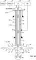
- FIG. 2B illustrates the wellbore 10 being drilled in a second stage of the disclosed process
- Fig. 2C illustrates the wellbore 10 being drilled in a third stage of the disclosed process should the process fail to maintain the steps in the first stage
- Fig. 3 illustrates the process 100 of closed hole circulation drilling with continuous downhole monitoring of the present disclosure.
- the drilling system 50 detects losses during the conventional drilling of the initial stage in Fig. 2A (Block 110). As is customary, not all losses may be of particular concern and may be handled by the current drilling technique. Therefore, a comparison is made to determine if the static loss rate is at least within some limit of the current drilling rate (Decision 120). For example, the static loss rate may be monitored and handled with conventional drilling techniques until the static loss rate reaches within a limit of about 50% ( i.e., half) of the current drilling rate. The value of the limit may depend on the drilling system 50, the formation being drilled, and other factors consistent with a given implementation.
- the current regime for the conventional drilling of the wellbore 10 may be reviewed to provide better well control.
- the control 55 may continue with the conventional drilling of the wellbore 10 with the system 50 in Fig. 2A , but the drilling may be modified using conventional adjustments, such as introducing lost circulation material (LCM) into the wellbore 10.
- LCM lost circulation material
- Knowledge of the formation may indicate when theft zones may be encountered during drilling, and the process 100 can be converted before.
- the control 55 evaluates the reasons for the losses. For example, operations may determine that a total loss or theft zone having natural fractures may have been encountered during the conventional drilling of the formation so that mud cap drilling needs to be implemented.
- Any gas migration into the mud cap 70 in the annulus 12 can be countered by bullheading the wellbore 10.
- Bullheading involves forcibly pumping the fluids in the wellbore 10 into the formation. This may be done by pumping into the annulus 12 from the surface. Typically, the volume, the time interval, and the rate for bullheading are calculated based on current conditions.
- the pumping rate is then increased in increments and held for a period at each increment until reaching a maximum drilling rate.
- the pumping rate can be brought up in 22 m 3 /hr (100 gpm) increments until reaching 136 m 3 /hr (600 gpm), which may be the maximum drilling rate as per the drilling program.
- the increase at each increment can be held for 2 minutes.
- the wellbore 10 may not need to be closed in this manner with the flow control device 58 and may remain open to atmosphere at surface. Either way, flow returns are not brought to the surface.
- the pressurized mud cap drilling cannot be sustained.
- the pump rates for pumping the sacrificial fluid 12 required to sustain the fluid level in the annulus 12 may exceed desired rates that can damage the mud pumps or cause other issues.
- the theft zone 16 may have a formation pressure that is below conventionally acceptable levels because the reservoir is in its depletion stage. For this reason, the wellbore 10 may not be kept full with even the lightest available fluid at the rig site.
- the wellbore 10 cannot be kept full so that the level of the mud cap 70 has receded in the annulus 12.
- the wellbore 10 may not be kept full because the theft zone 16 encountered may have a pressure gradient with formation fluid far below 1, 031 kg/m 3 (8.6-ppg).
- the theft zone 16 may have formation fluid with a weight of 839 kg/m 3 (7-ppg), and the lowest available mud weight for the mud cap 70 will likely be higher, such as 959 kg/m 3 (8-ppg). Consequently, the level of the mud cap 70 has dropped, resulting in the decrease in monitored pressure at the instrumentation 60.
- balance is reach when the wellbore pressure 10 is balanced with the reservoir pressure.
- CHCD Closed Hole Circulation Drilling
- Block 134 continuous downhole monitoring
- fluid returns are not brought up the annulus to surface.
- the wellbore 10 can remain closed with the rotating control device 56 (if used) so gasses can be diverted from the rig of the drilling system 50.
- the rotating control device 58 can be used so that the rotating control device 58 also creates a closed system, making it easier to control the well.
- the rotating control device 58 may not be used, and the wellbore 10 is closed in other known ways or may remain open to the atmosphere at surface.
- An emulsification 74 may develop at the interface between the sacrificial fluid 72, the formation fluid, and the annular mud cap 70.
- the emulsification 74 can initially keep formation gas 76 from migrating into the mud cap 70.
- significant migration of formation gas 76 in the mud cap 70 would alter the density of the mud cap 70, change the initial fluid level, and undermine the well control provided.
- bullheading the wellbore can be used to counter the gas migration. Because the drilling system 50 can perform continuous operational monitoring and diagnostics, any bullheading of the wellbore 10 is based on the actual behavior of the downhole conditions, rather than just blind bullheading based on the predicted/assumed variables.
- the level of the mud cap 70 may increase from the Initial Fluid Level (IFL) (Increase at Decision 140) due to a complete formation plug off, an influx/gas stream, or a reservoir pressure increase. This increase of the mud cap 70 from the Initial Fluid Level (IFL) may then decrease due to a partial plug-off of the formation. In general, should an increase be detected by the continuous monitoring, operators stop drilling, turn off the mud pumps 57, and bullhead the well. These steps will be discussed below.
- IFL Initial Fluid Level
- operations re-evaluate a new initial fluid level (IFL) for the mud cap 70 in the wellbore 10 (Block 165A) so operations can continue drilling with the continuous monitoring regime under this re-evaluated initial fluid level (Block 134).
- IFL initial fluid level
- the initial fluid level (IFL) needs to be re-evaluated based on the new reservoir pressure (Block 168) so operations can continue drilling with the continuous monitoring regime under this re-evaluated initial fluid level (Block 134).
- the pressure at the instrumentation 60 may show a decreasing trend so that operations stop drilling and turn the pumps 57 off. Operations then assess the reasons for the decreasing pressure.
- the pressure would not be expected to simply continue decreasing.
- the pressure decrease is expected to stop at some point when a balance is achieved with the reservoir pressure. If the pressure decreases, stops at some point, and then increases, the wellbore has possibly encountered another fractured theft zone.
- the fractured theft zone may produce a kick or influx due to the loss of the mud cap's hydrostatic head. In this case, operations bullhead the wellbore and re-evaluate the initial fluid level for the mud cap 70 (Block 184).
- a new liner can then be run downhole of the existing casing 11 and cemented in the open hole 14 to isolate the previously drilled zones of the formation.
- Such a liner can include additional downhole instrumentation 60 according to the present disclosure, and/or any existing instrumentation 60 on/in the previous section of casing 11 can still be used for monitoring the next hole sections.
- a retrievable downhole valve 61 with the instrumentation 60 can be used on top of the new liner.
- the bottom hole assembly is 56 is positioned above the downhole valve 61, which is then closed by the control 55 using umbilical (hydraulics) or non-umbilical (e.g ., RFID). Pressure can be bled off above the closed flapper valve 62, and the wellbore can be monitored to confirm isolation. The instrumentation 60 can then make measurements to detect gas migration using the pressure sensor 64.
- umbilical hydroaulics
- non-umbilical e.g ., RFID
- the pressure sensor 64 can monitor for an increase in the pressure downhole of the flapper 62 over time until it stabilizes and can estimate a rate of gas migration based on distance between the downhole valve 61 and a loss zone.
- the pressure at downhole valve 61 may be 20.7 MPa (3000 psi) when the flapper valve 62 is initially closed. The pressure may start increasing until it stabilizes at some level ( e.g ., 21.5 MPa (3120 psi)). This increase until stabilization would have taken a given amount of time, such as 60 min.
- the gas migration rate can be estimated to be about 13.8 kPa/min (2 psi/min).
- the gas will migrate from the first loss zone to the depth of the control valve 61, and the distance can be used for a rate estimation.
- the distance from the first loss zone in the wellbore 10 to the downhole valve 61 may be 305 m (1000 ft), and it may have taken 100 min for the monitored pressure at the downhole valve 61 to be stabilized.
- the migration rate can be estimated to be 3 m/min (10 ft/min). Or, if gas is already between valves 61, the estimation can use that distance.
- closing the flapper valve 62 might not be feasible as it requires pulling a few stands of the drillstring 22 out of hole so the valve 62 can be closed to check for gas migration.
- closing the flapper valve 62 can be done once to assess gas migration behavior of the reservoir with either water-based mud (WBM) or oil-based mud (OBM). This assessed behavior would then help to calculate bullheading volume, bullheading time interval, and bullheading rate based on the actual gas migration rate, not based on a predicted rate from simulation software.
- WBM water-based mud
- OBM oil-based mud
- teachings of the present disclosure can be implemented by the control 55 of the drilling system 50 in digital electronic circuitry, computer hardware, computer firmware, computer software, or any combination thereof.
- Teachings of the present disclosure can be implemented in a programmable storage device (computer program product tangibly embodied in a machine-readable storage device) for execution by a programmable control device or processor ( e.g ., of the control 55) so that the programmable processor executing program instructions can perform functions of the present disclosure.
- the teachings of the present disclosure can be implemented advantageously in one or more computer programs that are executable on a programmable system, such as the control 55 of the drilling system 50, including at least one programmable processor coupled to receive data and instructions from, and to transmit data and instructions to, a data storage system, at least one input device, and at least one output device.
- Storage devices suitable for tangibly embodying computer program instructions and data include all forms of non-volatile memory, including by way of example semiconductor memory devices, such as EPROM, EEPROM, and flash memory devices; magnetic disks such as internal hard disks and removable disks; magneto-optical disks; and CD-ROM disks. Any of the foregoing can be supplemented by, or incorporated in, ASICs (application-specific integrated circuits).
Landscapes
- Engineering & Computer Science (AREA)
- Life Sciences & Earth Sciences (AREA)
- Geology (AREA)
- Mining & Mineral Resources (AREA)
- Physics & Mathematics (AREA)
- Environmental & Geological Engineering (AREA)
- Fluid Mechanics (AREA)
- General Life Sciences & Earth Sciences (AREA)
- Geochemistry & Mineralogy (AREA)
- Mechanical Engineering (AREA)
- Earth Drilling (AREA)
Claims (18)
- Verfahren zum Bohren eines Bohrlochs (10) in einer Formation eines Reservoirs, wobei das Verfahren Folgendes umfasst:Bereitstellen einer Geräteausstattung (60), die einer im Bohrloch (10) angeordneten Verrohrung (11) zugeordnet ist;in einer ersten Phase erfolgendes Bohren eines offenen Lochabschnitts (14) des Bohrlochs in der Formation für eine über die Verrohrung (11) hinausgehende Ausdehnung durch Pumpen von Bohrfluid mit einer Bohrrate durch einen Bohrstrang (52) und Ermöglichen von Rückflüssen des Bohrfluids an die Oberfläche durch einen Ringraum (12) zwischen dem Bohrloch (10) und dem Bohrstrang (52);Ermitteln (110, 120) während der ersten Phase des Bohrens, dass eine statische Verlustrate des Bohrfluids zur Formation innerhalb eines Verlustzirkulationsgrenzwerts der Bohrrate liegt;als Antwort auf die Ermittlung (110, 120), (a) Füllen (124) des Ringraums (12) des Bohrlochs (10) mit einer Schlammkappe (70) aus Ringraumfluid bis zu einer Durchflusssteuerungsvorrichtung (58), (b) Bestimmen (130), dass der Ringraum (12) nicht bis zur Durchflusssteuerungsvorrichtung (58) mit dem Ringraumfluid gefüllt gehalten werden kann, (c) Ermöglichen, dass das Ringraumfluid im Ringraum (12) mit einem Reservoirdruck ins Gleichgewicht kommt, und (d) Definieren (134) eines anfänglichen Fluidniveaus (IFL) unterhalb der Durchflusssteuerungsvorrichtung (58), wo die Schlammkappe (70) im Ringraum (12) mit dem Reservoirdruck im Gleichgewicht ist, durch Überwachen eines Drucks im Ringraum (12) unter Verwendung der Geräteausstattung (60);in einer zweiten Phase erfolgendes Bohren des offenen Lochabschnitts (14) des Bohrlochs (10) in der Formation für eine anschließende Ausdehnung über die Verrohrung (11) hinaus, während der Ringraum (12) bis zum anfänglichen Fluidniveau (IFL) mit der Schlammkappe (70) gefüllt ist, durch: Pumpen (134) eines Opferfluids (72) durch den Bohrstrang (52) ohne Rückflüsse zur Oberfläche durch den Ringraum (12), und Überwachen der Schlammkappe (70) im Ringraum (12) durch Überwachen eines Drucks unter Verwendung der Geräteausstattung (60), um eine Änderung relativ zu dem anfänglichen Fluidniveau (IFL) zu ermitteln (140); undSteuern (150, 160, 180) des Bohrens als Antwort auf die ermittelte Änderung (140).
- Verfahren nach Anspruch 1, wobei das Ermitteln (110, 120), dass die statische Verlustrate des Bohrfluids innerhalb des Verlustzirkulationsgrenzwerts der Bohrrate liegt, das Ermitteln (110, 120), dass die statische Verlustrate des Bohrfluids innerhalb mindestens der Hälfte der Zirkulation bei der Bohrrate liegt, umfasst.
- Verfahren nach Anspruch 1 oder 2, wobei vor dem Schritt (a) des Füllens (124) des Ringraums (12) des Bohrlochs (10) mit der Schlammkappe (70) aus dem Ringraumfluid bis zur Durchflusssteuerungsvorrichtung (58) als Antwort auf die Ermittlung das Verfahren Folgendes umfasst:
Absperren des Ringraums (12) gegen Rückflüsse mit der Durchflusssteuerungsvorrichtung (58) und optional Installieren einer rotierenden Steuerungsvorrichtung (58), damit die Durchflusssteuerungsvorrichtung (58) den Ringraum (12) im Bohrloch (12) von der Oberfläche isoliert. - Verfahren nach Anspruch 3, wobei das Verfahren ferner den Schritt des Bohrens in einer Zwischenphase nach der ersten Phase, aber vor der zweiten Phase, durch Pumpen (134) des Opferfluids (72) durch den Bohrstrang (52) ohne Rückflüsse an die Oberfläche durch den Ringraum (12) und Gefüllthalten des Ringraums (12) bis zur Durchflusssteuerungsvorrichtung (58) mit der Schlammkappe (70) gefüllt, um einen Druck der Schlammkappe (70) im Ringraum an der Durchflusssteuerungsvorrichtung (58) beizubehalten.
- Verfahren nach Anspruch 4, wobei die Schritte (b) des Bestimmens (130) und (c) des Ermöglichens Folgendes umfassen:Bestimmen (130) während des Bohrens in der Zwischenphase, dass der Ringraum (12) nicht bis zur Durchflusssteuerungsvorrichtung (58) mit der Schlammkappe (70) gefüllt gehalten werden kann;Anhalten des Bohrens in der Zwischenphase; undErmöglichen, dass die Schlammkappe (70) im Ringraum (12) mit dem Reservoirdruck in einem Zustand ins Gleichgewicht kommt, der das anfängliche Fluidniveau (IFL) der Schlammkappe (70) im Ringraum (12) unterhalb der Durchflusssteuerungsvorrichtung (58) definiert (134).
- Verfahren nach Anspruch 1, wobei der Schritt (a) des Bestimmens (130), dass der Ringraum (12) nicht mit dem Ringraumfluid gefüllt gehalten werden kann, Folgendes umfasst:Bestimmen, dass das Bohrloch (10) unter Verwendung eines leichtesten der an einem Bohrturmstandort verfügbaren Ringraumfluide nicht voll gehalten werden kann; und/oderBestimmen, dass eine Pumprate zum Pumpen des Opferfluids einen Pumpraten-Grenzwert überschreitet.
- Verfahren nach Anspruch 6, wobei der Schritt (c) des Ermöglichens, dass das Ringraumfluid (12) im Ringraum mit dem Reservoirdruck ins Gleichgewicht kommt, Folgendes umfasst: Anhalten des Pumpens des Opferfluids; und Sinkenlassen eines Niveaus des Ringraumfluids im Bohrloch (10), bis es stabilisiert ist durch:Messen eines Drucks des Ringraumfluids im Ringraum (12) unter Verwendung der Geräteausstattung (60), bis sich der Druck innerhalb einer Druckspanne stabilisiert; und/oderÜberwachen des Niveaus, bis sich das Niveau innerhalb einer Niveauspanne stabilisiert.
- Verfahren nach einem der Ansprüche 1 bis 7, wobei das Bereitstellen der der Verrohrung (11) zugeordneten Geräteausstattung (60) das Bereitstellen der Geräteausstattung als Teil eines Absperrventils (62), das an der Verrohrung (11) im Bohrloch (10) angeordnet ist, umfasst, wobei optional die Geräteausstattung (60) einen Drucksensor umfasst, der einen Ringraumdruck in einer Tiefe im Bohrloch (10) misst, wobei der gemessene Druck verwendet wird, um das anfängliche Fluidniveau der Schlammkappe (70) im Ringraum (12) des Bohrlochs (10) zu bestimmen.
- Verfahren nach einem der Ansprüche 1 bis 8, wobei das Ermitteln (140) der Änderung und das Steuern (150, 160, 180) des Bohrens als Antwort auf die ermittelte Änderung Folgendes umfasst:Bestimmen, dass die ermittelte Änderung innerhalb eines Schwellenwerts liegt;Fortsetzen (150) des Bohrens des Bohrlochs (10) durch Pumpen (134) des Opferfluids (72) durch den Bohrstrang (52) ohne die Rückflüsse durch den Ringraum (12) an die Oberfläche; undZurückkehren zum Überwachen der Schlammkappe (70) im Ringraum (12), um eine nachfolgende Änderung relativ zum anfänglichen Fluidniveau (IFL) zu ermitteln (140).
- Verfahren nach einem der Ansprüche 1 bis 9, wobei das Steuern (150, 160, 180) des Bohrens als Antwort auf die ermittelte Änderung (140) Folgendes umfasst:Anhalten (160, 180) des Bohrens; undAbschalten (160, 180) des Pumpens des Opferfluids (72) den Bohrstrang (52) hinunter.
- Verfahren nach einem der Ansprüche 1 bis 10, wobei das Ermitteln (140) der Änderung und das Steuern (150, 160, 180) des Bohrens als Antwort auf die ermittelte Änderung Folgendes umfassen:Bestimmen, dass die ermittelte Änderung einen Anstieg des Niveaus der Schlammkappe (70) vom anfänglichen Fluidniveau (IFL) umfasst, durch Ermitteln (140) eines Anstiegs des Drucks, der in einer Tiefe im Ringraum (12) gemessen wird;Bestimmen, dass der in der Tiefe im Ringraum (12) gemessene Druck aufhört, anzusteigen (162) und dann abnimmt (164); undUmstellen vom Bohren des Bohrlochs (10) mit Schlammkappe (70) zum Bohren einer weiteren Ausdehnung des Bohrlochs (10) mit einer unterschiedlichen Bohrprozedur (165B).
- Verfahren nach einem der Ansprüche 1 bis 11, wobei das Ermitteln (140) der Änderung und das Steuern (150, 160, 180) des Bohrens als Antwort auf die ermittelte Änderung Folgendes umfassen:Bestimmen, dass die ermittelte Änderung einen Anstieg des Niveaus der Schlammkappe (70) vom anfänglichen Fluidniveau umfasst, durch Ermitteln (140) eines Anstiegs des Drucks, der in einer Tiefe im Ringraum (12) gemessen wird;Bestimmen, dass der in der Tiefe im Ringraum (12) gemessene Druck aufhört, anzusteigen (162), aber nicht abnimmt (164);Neubewerten (165A) des anfänglichen Fluidniveaus (IFL) der Schlammkappe (70); undBeginnen (165A) des Bohrens einer weiteren Ausdehnung des Bohrlochs (12) mit der Schlammkappe auf dem neu bewerteten Fluidniveau.
- Verfahren nach einem der Ansprüche 1 bis 12, wobei das Ermitteln (140) der Änderung und das Steuern (150, 160, 180) des Bohrens als Antwort auf die ermittelte Änderung Folgendes umfassen:Bestimmen (140), dass die ermittelte Änderung einen Anstieg des Niveaus der Schlammkappe (70) vom anfänglichen Fluidniveau (IFL) umfasst, durch Ermitteln (140) eines Anstiegs des Drucks, der in einer Tiefe im Ringraum (12) gemessen wird;Bestimmen (162), dass ein im Ringraum gemessener Druck weiter ansteigt; undBullheading (166) des Bohrlochs (10).
- Verfahren nach einem der Ansprüche 1 bis 13, wobei das Ermitteln (140) der Änderung und das Steuern (150, 160, 180) des Bohrens als Antwort auf die ermittelte Änderung Folgendes umfassen:Bestimmen, dass die ermittelte Änderung eine Abnahme des Niveaus der Schlammkappe (70) vom anfänglichen Fluidniveau (IFL) umfasst, durch Ermitteln (140) einer Abnahme des Drucks, der in einer Tiefe im Ringraum (12) gemessen wird; undBullheading (184) des Bohrlochs (10).
- Verfahren nach einem der Ansprüche 1 bis 14, wobei das Ermitteln (140) der Änderung und das Steuern (150, 160, 180) des Bohrens als Antwort auf die ermittelte Änderung Folgendes umfassen:Bestimmen, dass die ermittelte Änderung einen Anstieg des Niveaus der Schlammkappe (70) vom anfänglichen Fluidniveau (IFL) umfasst, durch Ermitteln (140) eines Anstiegs des Drucks, der in einer Tiefe im Ringraum (12) gemessen wird;Messen auf eine Temperaturänderung im Ringraumfluid in einer Tiefe im Ringraum (12), die eine Migration von Formationsgas in der Schlammkappe (70) angibt; undBullheading (168) des Bohrlochs (10) als Antwort darauf, dass die gemessene Temperaturänderung die Formationsgasmigration in der Schlammkappe (70) angibt.
- Verfahren nach einem der Ansprüche 1 bis 15, wobei das Ermitteln (140) der Änderung und das Steuern (150, 160, 180) des Bohrens als Antwort auf die ermittelte Änderung Folgendes umfassen:Bestimmen, dass die ermittelte Änderung einen Anstieg des Niveaus der Schlammkappe (70) vom anfänglichen Fluidniveau (IFL) umfasst, durch Ermitteln (140) eines Anstiegs des Drucks, der in einer Tiefe im Ringraum (12) gemessen wird;Messen auf ein Vorliegen eines Gases im Ringraumfluid in einer Tiefe im Ringraum (12), was eine Migration von Formationsgas in der Schlammkappe (70) angibt; undBullheading (184) des Bohrlochs (10) als Antwort darauf, dass das gemessene Vorliegen des Gases die Formationsgasmigration in der Schlammkappe (70) angibt.
- System zum Bohren eines Bohrlochs in einer Formation eines Reservoirs, wobei das System Folgendes umfasst:eine Geräteausstattung (60), die einer im Bohrloch (10) angeordneter Verrohrung (11) zugeordnet und dafür konfiguriert ist, einen Druck im Bohrloch (10) zu messen;Fluidhandhabungsausrüstung (50, 57, 59) und eine Durchflusssteuerungsvorrichtung (58), die dafür konfiguriert sind, Fluid in einem Bohrstrang (52) im Bohrloch und in einem Ringraum (12) zwischen dem Bohrstrang (52) und dem Bohrloch (10) zu handhaben, wobei das gehandhabte Fluid Bohrfluid, Rückflüsse, Ringraumfluid und Opferfluid einschließt;eine programmierbare Steuerungsvorrichtung (55), die kommunikationsfähig mit der Geräteausstattung (60) und der Fluidhandhabungsausrüstung (50, 57, 59) gekoppelt ist, wobei die programmierbare Steuerungsvorrichtung (55) zu Folgendem konfiguriert ist:das Bohrfluid mit einer Bohrrate durch den Bohrstrang (52) zu pumpen und die Rückflüsse an die Oberfläche durch den Ringraum (12) zu ermöglichen, um in einer ersten Phase einen offenen Lochabschnitt (14) des Bohrlochs (10) für eine Ausdehnung in der Formation zu bohren;während des Bohrens in der ersten Phase zu ermitteln (110, 120), dass eine statische Verlustrate des Bohrfluids innerhalb eines Verlustzirkulationsgrenzwerts der Bohrrate liegt;als Antwort auf die Ermittlung (110, 120) (a) den Ringraum des Bohrlochs bis zur Durchflusssteuerungsvorrichtung (58) mit einer Schlammkappe (70) des Ringraumfluids zu füllen (124), (b) zu bestimmen (130), dass der Ringraum (12) nicht bis zur Durchflusssteuerungsvorrichtung (58) mit dem Ringraumfluid gefüllt gehalten werden kann, (c) zu ermöglichen, dass das Ringraumfluid im Ringraum (12) mit einem Reservoirdruck ins Gleichgewicht kommt, (d) und ein anfängliches Fluidniveau (IFL) zu definieren (134), bei dem die Schlammkappe im Ringraum (12) mit dem Reservoirdruck im Gleichgewicht ist, wobei die Geräteausstattung (60) verwendet wird;das Opferfluid (72) durch den Bohrstrang (52) zu pumpen (134), ohne die Rückflüsse an die Oberfläche durch den Ringraum (12), um in einer zweiten Phase den offenen Lochabschnitt des Bohrlochs (10) für eine anschließende Ausdehnung über die Verrohrung (11) hinaus zu bohren, während der Ringraum (12) bis zum anfänglichen Fluidniveau (IFL) mit der Schlammkappe (70) gefüllt ist;die Schlammkappe (70) im Ringraum (12) unter Verwendung der Geräteausstattung (60) zu überwachen, um eine Änderung relativ zum anfänglichen Fluidniveau (IFL) zu ermitteln (140); unddas Bohren als Antwort auf die ermittelte Änderung (140) zu steuern (150, 160, 180).
- Programmierbare Speichervorrichtung mit darauf gespeicherten Anweisungen zum Bewirken, dass das System nach Anspruch 17 das Verfahren nach einem der Ansprüche 1 bis 16 zum Bohren eines Bohrlochs (10) in einer Formation eines Reservoirs durchführt.
Applications Claiming Priority (2)
| Application Number | Priority Date | Filing Date | Title |
|---|---|---|---|
| US16/435,529 US11199061B2 (en) | 2019-06-09 | 2019-06-09 | Closed hole circulation drilling with continuous downhole monitoring |
| PCT/US2020/035892 WO2020251820A1 (en) | 2019-06-09 | 2020-06-03 | Closed hole circulation drilling with continuous downhole monitoring |
Publications (2)
| Publication Number | Publication Date |
|---|---|
| EP3980624A1 EP3980624A1 (de) | 2022-04-13 |
| EP3980624B1 true EP3980624B1 (de) | 2025-03-12 |
Family
ID=71465402
Family Applications (1)
| Application Number | Title | Priority Date | Filing Date |
|---|---|---|---|
| EP20736806.9A Active EP3980624B1 (de) | 2019-06-09 | 2020-06-03 | Umlaufbohrung in einem geschlossenen loch mit kontinuierlicher bohrlochüberwachung |
Country Status (5)
| Country | Link |
|---|---|
| US (1) | US11199061B2 (de) |
| EP (1) | EP3980624B1 (de) |
| AU (1) | AU2020293054B2 (de) |
| CA (1) | CA3140719A1 (de) |
| WO (1) | WO2020251820A1 (de) |
Families Citing this family (2)
| Publication number | Priority date | Publication date | Assignee | Title |
|---|---|---|---|---|
| EP4305125A1 (de) * | 2021-03-09 | 2024-01-17 | ExxonMobil Technology and Engineering Company | Flüssigkeiten mit hohlen glaskügelchen (hgb) mit geringer dichte für bohrlochbohr-, -abschluss- und -arbeitsvorgänge |
| US12173571B2 (en) | 2023-04-25 | 2024-12-24 | Saudi Arabian Oil Company | System and method to measure mud level of mud cap in a wellbore annulus |
Family Cites Families (9)
| Publication number | Priority date | Publication date | Assignee | Title |
|---|---|---|---|---|
| US7237623B2 (en) | 2003-09-19 | 2007-07-03 | Weatherford/Lamb, Inc. | Method for pressurized mud cap and reverse circulation drilling from a floating drilling rig using a sealed marine riser |
| WO2007005822A2 (en) * | 2005-07-01 | 2007-01-11 | Board Of Regents, The University Of Texas System | System, program products, and methods for controlling drilling fluid parameters |
| GB2542968A (en) | 2014-06-10 | 2017-04-05 | Mhwirth As | Method for detecting wellbore influx |
| EP3201423B1 (de) * | 2014-10-03 | 2023-05-03 | Weatherford Technology Holdings, LLC | Integriertes bohrsteuerungssystem und zugehöriges verfahren |
| EP3578753B1 (de) | 2016-05-12 | 2021-02-24 | Enhanced Drilling AS | Systeme und verfahren zum kontrollierten bohren von schlammkappen |
| WO2017115344A2 (en) | 2016-05-24 | 2017-07-06 | Future Well Control As | Drilling system and method |
| US10648315B2 (en) | 2016-06-29 | 2020-05-12 | Schlumberger Technology Corporation | Automated well pressure control and gas handling system and method |
| US10415366B2 (en) * | 2017-12-07 | 2019-09-17 | Nabors Drilling Technologies Usa, Inc. | Rig control apparatus, system, and method |
| US10988997B2 (en) * | 2018-01-22 | 2021-04-27 | Safekick Americas Llc | Method and system for safe pressurized mud cap drilling |
-
2019
- 2019-06-09 US US16/435,529 patent/US11199061B2/en active Active
-
2020
- 2020-06-03 EP EP20736806.9A patent/EP3980624B1/de active Active
- 2020-06-03 CA CA3140719A patent/CA3140719A1/en active Pending
- 2020-06-03 WO PCT/US2020/035892 patent/WO2020251820A1/en not_active Ceased
- 2020-06-03 AU AU2020293054A patent/AU2020293054B2/en active Active
Also Published As
| Publication number | Publication date |
|---|---|
| US20200386065A1 (en) | 2020-12-10 |
| US11199061B2 (en) | 2021-12-14 |
| CA3140719A1 (en) | 2020-12-17 |
| WO2020251820A1 (en) | 2020-12-17 |
| AU2020293054B2 (en) | 2025-05-22 |
| AU2020293054A1 (en) | 2022-01-20 |
| EP3980624A1 (de) | 2022-04-13 |
Similar Documents
| Publication | Publication Date | Title |
|---|---|---|
| US9328574B2 (en) | Method for characterizing subsurface formations using fluid pressure response during drilling operations | |
| US7984770B2 (en) | Method for determining formation integrity and optimum drilling parameters during drilling | |
| US9677337B2 (en) | Testing while fracturing while drilling | |
| US11035184B2 (en) | Method of drilling a subterranean borehole | |
| CN102933791B (zh) | 用于保持钻井压力的方法 | |
| WO2015190932A1 (en) | Method for detecting wellbore influx | |
| US20120227961A1 (en) | Method for automatic pressure control during drilling including correction for drill string movement | |
| CN105143600B (zh) | 关于双梯度钻井的井监测、感测、控制和泥浆测井 | |
| US20170335654A1 (en) | Pressure relief valve set point systems | |
| NO20170139A1 (en) | Control of a managed pressure drilling system | |
| EP3980624B1 (de) | Umlaufbohrung in einem geschlossenen loch mit kontinuierlicher bohrlochüberwachung | |
| Aldred et al. | Using downhole annular pressure measurements to improve drilling performance | |
| US10954731B2 (en) | Foam cap drilling methods | |
| US20140190751A1 (en) | Method and System for Drilling with Reduced Surface Pressure | |
| Elliott et al. | Managed pressure drilling erases the lines | |
| Elgibaly | Well control during drilling and workover operations | |
| US12055001B2 (en) | Monobore drilling methods with managed pressure drilling | |
| Hannegan et al. | HPHT Well Construction with Closed-Loop Cementing Technology | |
| Veisene | Well Control During Extended Reach Drilling–Conventional Drilling Compared to the Reelwell Drilling Method | |
| Valstad | Parameter Estimation and Control of a Dual Gradient Managed Pressure Drilling System | |
| Carpenter | Managed-pressure-drilling technology succeeds in the harding field |
Legal Events
| Date | Code | Title | Description |
|---|---|---|---|
| STAA | Information on the status of an ep patent application or granted ep patent |
Free format text: STATUS: UNKNOWN |
|
| STAA | Information on the status of an ep patent application or granted ep patent |
Free format text: STATUS: THE INTERNATIONAL PUBLICATION HAS BEEN MADE |
|
| PUAI | Public reference made under article 153(3) epc to a published international application that has entered the european phase |
Free format text: ORIGINAL CODE: 0009012 |
|
| STAA | Information on the status of an ep patent application or granted ep patent |
Free format text: STATUS: REQUEST FOR EXAMINATION WAS MADE |
|
| 17P | Request for examination filed |
Effective date: 20211026 |
|
| AK | Designated contracting states |
Kind code of ref document: A1 Designated state(s): AL AT BE BG CH CY CZ DE DK EE ES FI FR GB GR HR HU IE IS IT LI LT LU LV MC MK MT NL NO PL PT RO RS SE SI SK SM TR |
|
| DAV | Request for validation of the european patent (deleted) | ||
| DAX | Request for extension of the european patent (deleted) | ||
| STAA | Information on the status of an ep patent application or granted ep patent |
Free format text: STATUS: EXAMINATION IS IN PROGRESS |
|
| 17Q | First examination report despatched |
Effective date: 20221130 |
|
| P01 | Opt-out of the competence of the unified patent court (upc) registered |
Effective date: 20230922 |
|
| GRAP | Despatch of communication of intention to grant a patent |
Free format text: ORIGINAL CODE: EPIDOSNIGR1 |
|
| STAA | Information on the status of an ep patent application or granted ep patent |
Free format text: STATUS: GRANT OF PATENT IS INTENDED |
|
| INTG | Intention to grant announced |
Effective date: 20241128 |
|
| GRAS | Grant fee paid |
Free format text: ORIGINAL CODE: EPIDOSNIGR3 |
|
| GRAA | (expected) grant |
Free format text: ORIGINAL CODE: 0009210 |
|
| STAA | Information on the status of an ep patent application or granted ep patent |
Free format text: STATUS: THE PATENT HAS BEEN GRANTED |
|
| AK | Designated contracting states |
Kind code of ref document: B1 Designated state(s): AL AT BE BG CH CY CZ DE DK EE ES FI FR GB GR HR HU IE IS IT LI LT LU LV MC MK MT NL NO PL PT RO RS SE SI SK SM TR |
|
| REG | Reference to a national code |
Ref country code: GB Ref legal event code: FG4D |
|
| REG | Reference to a national code |
Ref country code: CH Ref legal event code: EP |
|
| REG | Reference to a national code |
Ref country code: DE Ref legal event code: R096 Ref document number: 602020047587 Country of ref document: DE |
|
| REG | Reference to a national code |
Ref country code: IE Ref legal event code: FG4D |
|
| PG25 | Lapsed in a contracting state [announced via postgrant information from national office to epo] |
Ref country code: RS Free format text: LAPSE BECAUSE OF FAILURE TO SUBMIT A TRANSLATION OF THE DESCRIPTION OR TO PAY THE FEE WITHIN THE PRESCRIBED TIME-LIMIT Effective date: 20250612 |
|
| PG25 | Lapsed in a contracting state [announced via postgrant information from national office to epo] |
Ref country code: FI Free format text: LAPSE BECAUSE OF FAILURE TO SUBMIT A TRANSLATION OF THE DESCRIPTION OR TO PAY THE FEE WITHIN THE PRESCRIBED TIME-LIMIT Effective date: 20250312 |
|
| PGFP | Annual fee paid to national office [announced via postgrant information from national office to epo] |
Ref country code: DE Payment date: 20250402 Year of fee payment: 6 |
|
| PG25 | Lapsed in a contracting state [announced via postgrant information from national office to epo] |
Ref country code: ES Free format text: LAPSE BECAUSE OF FAILURE TO SUBMIT A TRANSLATION OF THE DESCRIPTION OR TO PAY THE FEE WITHIN THE PRESCRIBED TIME-LIMIT Effective date: 20250312 |
|
| PGFP | Annual fee paid to national office [announced via postgrant information from national office to epo] |
Ref country code: GB Payment date: 20250401 Year of fee payment: 6 |
|
| REG | Reference to a national code |
Ref country code: LT Ref legal event code: MG9D |
|
| PGFP | Annual fee paid to national office [announced via postgrant information from national office to epo] |
Ref country code: NO Payment date: 20250610 Year of fee payment: 6 |
|
| PG25 | Lapsed in a contracting state [announced via postgrant information from national office to epo] |
Ref country code: HR Free format text: LAPSE BECAUSE OF FAILURE TO SUBMIT A TRANSLATION OF THE DESCRIPTION OR TO PAY THE FEE WITHIN THE PRESCRIBED TIME-LIMIT Effective date: 20250312 |
|
| REG | Reference to a national code |
Ref country code: NL Ref legal event code: MP Effective date: 20250312 |
|
| PG25 | Lapsed in a contracting state [announced via postgrant information from national office to epo] |
Ref country code: LV Free format text: LAPSE BECAUSE OF FAILURE TO SUBMIT A TRANSLATION OF THE DESCRIPTION OR TO PAY THE FEE WITHIN THE PRESCRIBED TIME-LIMIT Effective date: 20250312 |
|
| PG25 | Lapsed in a contracting state [announced via postgrant information from national office to epo] |
Ref country code: BG Free format text: LAPSE BECAUSE OF FAILURE TO SUBMIT A TRANSLATION OF THE DESCRIPTION OR TO PAY THE FEE WITHIN THE PRESCRIBED TIME-LIMIT Effective date: 20250312 Ref country code: GR Free format text: LAPSE BECAUSE OF FAILURE TO SUBMIT A TRANSLATION OF THE DESCRIPTION OR TO PAY THE FEE WITHIN THE PRESCRIBED TIME-LIMIT Effective date: 20250613 |
|
| REG | Reference to a national code |
Ref country code: AT Ref legal event code: MK05 Ref document number: 1775135 Country of ref document: AT Kind code of ref document: T Effective date: 20250312 |
|
| PG25 | Lapsed in a contracting state [announced via postgrant information from national office to epo] |
Ref country code: NL Free format text: LAPSE BECAUSE OF FAILURE TO SUBMIT A TRANSLATION OF THE DESCRIPTION OR TO PAY THE FEE WITHIN THE PRESCRIBED TIME-LIMIT Effective date: 20250312 |
|
| PG25 | Lapsed in a contracting state [announced via postgrant information from national office to epo] |
Ref country code: SE Free format text: LAPSE BECAUSE OF FAILURE TO SUBMIT A TRANSLATION OF THE DESCRIPTION OR TO PAY THE FEE WITHIN THE PRESCRIBED TIME-LIMIT Effective date: 20250312 |
|
| PG25 | Lapsed in a contracting state [announced via postgrant information from national office to epo] |
Ref country code: SM Free format text: LAPSE BECAUSE OF FAILURE TO SUBMIT A TRANSLATION OF THE DESCRIPTION OR TO PAY THE FEE WITHIN THE PRESCRIBED TIME-LIMIT Effective date: 20250312 |
|
| PG25 | Lapsed in a contracting state [announced via postgrant information from national office to epo] |
Ref country code: PT Free format text: LAPSE BECAUSE OF FAILURE TO SUBMIT A TRANSLATION OF THE DESCRIPTION OR TO PAY THE FEE WITHIN THE PRESCRIBED TIME-LIMIT Effective date: 20250714 |
|
| PG25 | Lapsed in a contracting state [announced via postgrant information from national office to epo] |
Ref country code: IT Free format text: LAPSE BECAUSE OF FAILURE TO SUBMIT A TRANSLATION OF THE DESCRIPTION OR TO PAY THE FEE WITHIN THE PRESCRIBED TIME-LIMIT Effective date: 20250312 Ref country code: PL Free format text: LAPSE BECAUSE OF FAILURE TO SUBMIT A TRANSLATION OF THE DESCRIPTION OR TO PAY THE FEE WITHIN THE PRESCRIBED TIME-LIMIT Effective date: 20250312 |
|
| PG25 | Lapsed in a contracting state [announced via postgrant information from national office to epo] |
Ref country code: AT Free format text: LAPSE BECAUSE OF FAILURE TO SUBMIT A TRANSLATION OF THE DESCRIPTION OR TO PAY THE FEE WITHIN THE PRESCRIBED TIME-LIMIT Effective date: 20250312 |
|
| PG25 | Lapsed in a contracting state [announced via postgrant information from national office to epo] |
Ref country code: CZ Free format text: LAPSE BECAUSE OF FAILURE TO SUBMIT A TRANSLATION OF THE DESCRIPTION OR TO PAY THE FEE WITHIN THE PRESCRIBED TIME-LIMIT Effective date: 20250312 Ref country code: EE Free format text: LAPSE BECAUSE OF FAILURE TO SUBMIT A TRANSLATION OF THE DESCRIPTION OR TO PAY THE FEE WITHIN THE PRESCRIBED TIME-LIMIT Effective date: 20250312 |
|
| PG25 | Lapsed in a contracting state [announced via postgrant information from national office to epo] |
Ref country code: RO Free format text: LAPSE BECAUSE OF FAILURE TO SUBMIT A TRANSLATION OF THE DESCRIPTION OR TO PAY THE FEE WITHIN THE PRESCRIBED TIME-LIMIT Effective date: 20250312 |
|
| PG25 | Lapsed in a contracting state [announced via postgrant information from national office to epo] |
Ref country code: SK Free format text: LAPSE BECAUSE OF FAILURE TO SUBMIT A TRANSLATION OF THE DESCRIPTION OR TO PAY THE FEE WITHIN THE PRESCRIBED TIME-LIMIT Effective date: 20250312 |
|
| PG25 | Lapsed in a contracting state [announced via postgrant information from national office to epo] |
Ref country code: IS Free format text: LAPSE BECAUSE OF FAILURE TO SUBMIT A TRANSLATION OF THE DESCRIPTION OR TO PAY THE FEE WITHIN THE PRESCRIBED TIME-LIMIT Effective date: 20250712 |
|
| REG | Reference to a national code |
Ref country code: DE Ref legal event code: R097 Ref document number: 602020047587 Country of ref document: DE |
|
| PG25 | Lapsed in a contracting state [announced via postgrant information from national office to epo] |
Ref country code: DK Free format text: LAPSE BECAUSE OF FAILURE TO SUBMIT A TRANSLATION OF THE DESCRIPTION OR TO PAY THE FEE WITHIN THE PRESCRIBED TIME-LIMIT Effective date: 20250312 |
|
| PLBE | No opposition filed within time limit |
Free format text: ORIGINAL CODE: 0009261 |
|
| STAA | Information on the status of an ep patent application or granted ep patent |
Free format text: STATUS: NO OPPOSITION FILED WITHIN TIME LIMIT |
|
| REG | Reference to a national code |
Ref country code: CH Ref legal event code: L10 Free format text: ST27 STATUS EVENT CODE: U-0-0-L10-L00 (AS PROVIDED BY THE NATIONAL OFFICE) Effective date: 20260121 |
|
| REG | Reference to a national code |
Ref country code: CH Ref legal event code: H13 Free format text: ST27 STATUS EVENT CODE: U-0-0-H10-H13 (AS PROVIDED BY THE NATIONAL OFFICE) Effective date: 20260127 |
|
| PG25 | Lapsed in a contracting state [announced via postgrant information from national office to epo] |
Ref country code: MC Free format text: LAPSE BECAUSE OF FAILURE TO SUBMIT A TRANSLATION OF THE DESCRIPTION OR TO PAY THE FEE WITHIN THE PRESCRIBED TIME-LIMIT Effective date: 20250312 |
|
| PG25 | Lapsed in a contracting state [announced via postgrant information from national office to epo] |
Ref country code: LU Free format text: LAPSE BECAUSE OF NON-PAYMENT OF DUE FEES Effective date: 20250603 |
|
| 26N | No opposition filed |
Effective date: 20251215 |
|
| REG | Reference to a national code |
Ref country code: BE Ref legal event code: MM Effective date: 20250630 |
|
| PG25 | Lapsed in a contracting state [announced via postgrant information from national office to epo] |
Ref country code: IE Free format text: LAPSE BECAUSE OF NON-PAYMENT OF DUE FEES Effective date: 20250603 |
|
| PG25 | Lapsed in a contracting state [announced via postgrant information from national office to epo] |
Ref country code: BE Free format text: LAPSE BECAUSE OF NON-PAYMENT OF DUE FEES Effective date: 20250630 |
|
| PG25 | Lapsed in a contracting state [announced via postgrant information from national office to epo] |
Ref country code: FR Free format text: LAPSE BECAUSE OF NON-PAYMENT OF DUE FEES Effective date: 20250630 |
|
| PG25 | Lapsed in a contracting state [announced via postgrant information from national office to epo] |
Ref country code: CH Free format text: LAPSE BECAUSE OF NON-PAYMENT OF DUE FEES Effective date: 20250630 |