EP3981494A1 - Élément filtrant rond, en particulier pour la filtration de gaz - Google Patents
Élément filtrant rond, en particulier pour la filtration de gaz Download PDFInfo
- Publication number
- EP3981494A1 EP3981494A1 EP21210689.2A EP21210689A EP3981494A1 EP 3981494 A1 EP3981494 A1 EP 3981494A1 EP 21210689 A EP21210689 A EP 21210689A EP 3981494 A1 EP3981494 A1 EP 3981494A1
- Authority
- EP
- European Patent Office
- Prior art keywords
- filter
- filter element
- round
- medium body
- positioning element
- Prior art date
- Legal status (The legal status is an assumption and is not a legal conclusion. Google has not performed a legal analysis and makes no representation as to the accuracy of the status listed.)
- Withdrawn
Links
- 238000001914 filtration Methods 0.000 title claims description 12
- 238000007789 sealing Methods 0.000 claims description 46
- 239000012530 fluid Substances 0.000 abstract description 31
- 238000013461 design Methods 0.000 description 11
- 230000002093 peripheral effect Effects 0.000 description 6
- 238000002485 combustion reaction Methods 0.000 description 3
- 239000000463 material Substances 0.000 description 3
- 239000004033 plastic Substances 0.000 description 3
- 229920003023 plastic Polymers 0.000 description 3
- 238000000926 separation method Methods 0.000 description 3
- 238000007373 indentation Methods 0.000 description 2
- 238000012423 maintenance Methods 0.000 description 2
- 238000004519 manufacturing process Methods 0.000 description 2
- 229920002635 polyurethane Polymers 0.000 description 2
- 239000004814 polyurethane Substances 0.000 description 2
- 229920005830 Polyurethane Foam Polymers 0.000 description 1
- 230000005540 biological transmission Effects 0.000 description 1
- 238000011161 development Methods 0.000 description 1
- 230000018109 developmental process Effects 0.000 description 1
- 238000002347 injection Methods 0.000 description 1
- 239000007924 injection Substances 0.000 description 1
- 238000001746 injection moulding Methods 0.000 description 1
- 238000003780 insertion Methods 0.000 description 1
- 230000037431 insertion Effects 0.000 description 1
- 238000009434 installation Methods 0.000 description 1
- 239000002245 particle Substances 0.000 description 1
- 239000011496 polyurethane foam Substances 0.000 description 1
- 239000002994 raw material Substances 0.000 description 1
- 229920001169 thermoplastic Polymers 0.000 description 1
- 239000004416 thermosoftening plastic Substances 0.000 description 1
Images


Classifications
-
- B—PERFORMING OPERATIONS; TRANSPORTING
- B01—PHYSICAL OR CHEMICAL PROCESSES OR APPARATUS IN GENERAL
- B01D—SEPARATION
- B01D46/00—Filters or filtering processes specially modified for separating dispersed particles from gases or vapours
- B01D46/24—Particle separators, e.g. dust precipitators, using rigid hollow filter bodies
- B01D46/2403—Particle separators, e.g. dust precipitators, using rigid hollow filter bodies characterised by the physical shape or structure of the filtering element
- B01D46/2411—Filter cartridges
- B01D46/2414—End caps including additional functions or special forms
-
- B—PERFORMING OPERATIONS; TRANSPORTING
- B01—PHYSICAL OR CHEMICAL PROCESSES OR APPARATUS IN GENERAL
- B01D—SEPARATION
- B01D27/00—Cartridge filters of the throw-away type
- B01D27/08—Construction of the casing
-
- B—PERFORMING OPERATIONS; TRANSPORTING
- B01—PHYSICAL OR CHEMICAL PROCESSES OR APPARATUS IN GENERAL
- B01D—SEPARATION
- B01D46/00—Filters or filtering processes specially modified for separating dispersed particles from gases or vapours
- B01D46/0002—Casings; Housings; Frame constructions
- B01D46/0005—Mounting of filtering elements within casings, housings or frames
-
- B—PERFORMING OPERATIONS; TRANSPORTING
- B01—PHYSICAL OR CHEMICAL PROCESSES OR APPARATUS IN GENERAL
- B01D—SEPARATION
- B01D46/00—Filters or filtering processes specially modified for separating dispersed particles from gases or vapours
- B01D46/24—Particle separators, e.g. dust precipitators, using rigid hollow filter bodies
-
- B—PERFORMING OPERATIONS; TRANSPORTING
- B01—PHYSICAL OR CHEMICAL PROCESSES OR APPARATUS IN GENERAL
- B01D—SEPARATION
- B01D46/00—Filters or filtering processes specially modified for separating dispersed particles from gases or vapours
- B01D46/52—Particle separators, e.g. dust precipitators, using filters embodying folded corrugated or wound sheet material
-
- B—PERFORMING OPERATIONS; TRANSPORTING
- B01—PHYSICAL OR CHEMICAL PROCESSES OR APPARATUS IN GENERAL
- B01D—SEPARATION
- B01D46/00—Filters or filtering processes specially modified for separating dispersed particles from gases or vapours
- B01D46/52—Particle separators, e.g. dust precipitators, using filters embodying folded corrugated or wound sheet material
- B01D46/521—Particle separators, e.g. dust precipitators, using filters embodying folded corrugated or wound sheet material using folded, pleated material
-
- F—MECHANICAL ENGINEERING; LIGHTING; HEATING; WEAPONS; BLASTING
- F02—COMBUSTION ENGINES; HOT-GAS OR COMBUSTION-PRODUCT ENGINE PLANTS
- F02M—SUPPLYING COMBUSTION ENGINES IN GENERAL WITH COMBUSTIBLE MIXTURES OR CONSTITUENTS THEREOF
- F02M35/00—Combustion-air cleaners, air intakes, intake silencers, or induction systems specially adapted for, or arranged on, internal-combustion engines
- F02M35/02—Air cleaners
- F02M35/0201—Housings; Casings; Frame constructions; Lids; Manufacturing or assembling thereof
-
- F—MECHANICAL ENGINEERING; LIGHTING; HEATING; WEAPONS; BLASTING
- F02—COMBUSTION ENGINES; HOT-GAS OR COMBUSTION-PRODUCT ENGINE PLANTS
- F02M—SUPPLYING COMBUSTION ENGINES IN GENERAL WITH COMBUSTIBLE MIXTURES OR CONSTITUENTS THEREOF
- F02M35/00—Combustion-air cleaners, air intakes, intake silencers, or induction systems specially adapted for, or arranged on, internal-combustion engines
- F02M35/02—Air cleaners
- F02M35/024—Air cleaners using filters, e.g. moistened
- F02M35/02416—Fixing, mounting, supporting or arranging filter elements; Filter element cartridges
-
- F—MECHANICAL ENGINEERING; LIGHTING; HEATING; WEAPONS; BLASTING
- F02—COMBUSTION ENGINES; HOT-GAS OR COMBUSTION-PRODUCT ENGINE PLANTS
- F02M—SUPPLYING COMBUSTION ENGINES IN GENERAL WITH COMBUSTIBLE MIXTURES OR CONSTITUENTS THEREOF
- F02M35/00—Combustion-air cleaners, air intakes, intake silencers, or induction systems specially adapted for, or arranged on, internal-combustion engines
- F02M35/02—Air cleaners
- F02M35/024—Air cleaners using filters, e.g. moistened
- F02M35/02441—Materials or structure of filter elements, e.g. foams
- F02M35/0245—Pleated, folded, corrugated filter elements, e.g. made of paper
-
- F—MECHANICAL ENGINEERING; LIGHTING; HEATING; WEAPONS; BLASTING
- F02—COMBUSTION ENGINES; HOT-GAS OR COMBUSTION-PRODUCT ENGINE PLANTS
- F02M—SUPPLYING COMBUSTION ENGINES IN GENERAL WITH COMBUSTIBLE MIXTURES OR CONSTITUENTS THEREOF
- F02M35/00—Combustion-air cleaners, air intakes, intake silencers, or induction systems specially adapted for, or arranged on, internal-combustion engines
- F02M35/02—Air cleaners
- F02M35/024—Air cleaners using filters, e.g. moistened
- F02M35/02475—Air cleaners using filters, e.g. moistened characterised by the shape of the filter element
- F02M35/02483—Cylindrical, conical, oval, spherical or the like filter elements; wounded filter elements
-
- B—PERFORMING OPERATIONS; TRANSPORTING
- B01—PHYSICAL OR CHEMICAL PROCESSES OR APPARATUS IN GENERAL
- B01D—SEPARATION
- B01D2265/00—Casings, housings or mounting for filters specially adapted for separating dispersed particles from gases or vapours
- B01D2265/02—Non-permanent measures for connecting different parts of the filter
- B01D2265/021—Anti-rotational means
-
- B—PERFORMING OPERATIONS; TRANSPORTING
- B01—PHYSICAL OR CHEMICAL PROCESSES OR APPARATUS IN GENERAL
- B01D—SEPARATION
- B01D2265/00—Casings, housings or mounting for filters specially adapted for separating dispersed particles from gases or vapours
- B01D2265/02—Non-permanent measures for connecting different parts of the filter
- B01D2265/024—Mounting aids
- B01D2265/026—Mounting aids with means for avoiding false mounting
-
- B—PERFORMING OPERATIONS; TRANSPORTING
- B01—PHYSICAL OR CHEMICAL PROCESSES OR APPARATUS IN GENERAL
- B01D—SEPARATION
- B01D2271/00—Sealings for filters specially adapted for separating dispersed particles from gases or vapours
- B01D2271/02—Gaskets, sealings
- B01D2271/027—Radial sealings
-
- B—PERFORMING OPERATIONS; TRANSPORTING
- B01—PHYSICAL OR CHEMICAL PROCESSES OR APPARATUS IN GENERAL
- B01D—SEPARATION
- B01D2275/00—Filter media structures for filters specially adapted for separating dispersed particles from gases or vapours
- B01D2275/20—Shape of filtering material
- B01D2275/208—Oval shape
-
- B—PERFORMING OPERATIONS; TRANSPORTING
- B01—PHYSICAL OR CHEMICAL PROCESSES OR APPARATUS IN GENERAL
- B01D—SEPARATION
- B01D2279/00—Filters adapted for separating dispersed particles from gases or vapours specially modified for specific uses
- B01D2279/60—Filters adapted for separating dispersed particles from gases or vapours specially modified for specific uses for the intake of internal combustion engines or turbines
Definitions
- the invention relates to a round filter element, in particular for gas filtration, according to the preamble of claim 1.
- the filter element is provided with a hollow-cylindrical filter medium body, on the outside of which a support grid is arranged to support the filter medium body.
- a V-shaped incision is made in the outer lateral surface of the filter medium body, in which a rod-shaped positioning element is inserted which, when installed in the receiving filter housing, prevents unintentional rotation about the longitudinal axis of the filter element.
- the walls in the area of the V-shaped incision of the filter medium body are sealed in a flow-tight manner.
- the object of the invention is to design a round filter element with simple structural measures in such a way that the round filter element is securely accommodated in the filter housing when installed.
- the round filter element according to the invention is preferably used for gas filtration, for example for filtration of air, in particular in the intake tract of an internal combustion engine of a vehicle.
- the filter element has a filter medium body, through the wall of which the fluid to be cleaned flows.
- the filter media body encloses an internal flow space defined by the inner wall of the filter media body.
- the flow through the filter medium body is in a radial direction, preferably radially from the inside to the outside, so that the internal flow space is adjacent to the untreated side of the filter medium body and the outside of the filter medium body forms the clean side through which the cleaned fluid exits.
- At least on one axial end face, preferably on both opposite axial end faces, the filter medium body is covered by end disks in a flow-tight manner.
- one end plate has a central opening communicating with the inner flow space for the axial flow guidance of the fluid; the opposite end plate, on the other hand, is closed and tightly seals the inner flow space axially to the outside.
- the end disk on the filter element which is provided with the central opening, is expediently designed to be rounded on its radial inner side, which makes it easier for the raw air to flow into the interior of the filter medium body. This is of particular importance for the inflow into the interior of the filter element for minimizing the overall pressure loss if, as is preferred in the present case, the air flows freely into the interior and, as is also preferred in the present case, no flow pipe leading the air flow directly into the interior is provided.
- the radius of the rounding is advantageously larger on the radial inside of the end disk than on the radial outside. If necessary, the radius on the radial inner side is designed so large that the start of the radius on the end face is still within the contour of the filter medium body.
- the radius of the rounding on the radial inside of the end disk is, for example, in a range between 5 mm and 15 mm, for example 7.5 mm.
- the round filter element with the filter medium body can be hollow-cylindrical or non-rotationally symmetrical, for example, have an oval or ovalized cross-sectional shape, whereby cross-sectional shapes with parallel longitudinal sides and semicircular narrow sides can also be considered and the longitudinal sides can be slightly convex or concave curved outwards or inwards.
- the inner wall and the outer wall of the filter media body are concentric with each other so that the filter media body has a constant radial thickness, although embodiments are also possible in which the filter media body has a varying radial thickness along its circumference.
- the round filter element has a cross-sectional shape that tapers in the axial direction, so that the outer circumference of the round filter element in the area of the first end disk is different in size compared to the outer circumference of the round filter element in the area of the opposite, second end disk.
- Round cross-sectional shapes in the area of both end disks are also possible in this embodiment, so that the round filter element and the filter medium body are designed in the shape of a cone. Furthermore, it is also possible to provide an oval or ovalized cross-sectional shape in the area of both end plates.
- the end disk can be closed on the end face with a smaller outer circumference and axially close off the inner flow space, whereas the opposite end plate has a flow opening on the larger outer circumference for introducing fluid into the inner flow space.
- end disk is closed on the end face with a larger outer circumference and axially closes the inner flow space and the opposite end plate has a flow opening on the smaller outer circumference for introducing fluid into the inner flow space.
- the round filter element according to the invention has a support grid on the outer wall of the filter medium body, which is designed in particular to be dimensionally stable.
- the support grid is designed, for example, as a thermoplastic injection molded part. Due to the flow through the filter medium body radially from the inside to the outside, the wall of the filter medium body is subject to a pressure directed radially outwards, under which pressure the wall tends to curve outwards.
- the support grid on the outer wall of the filter medium body prevents deformation of the wall radially outwards and thus keeps the filter medium body in shape during filtration, so that deformation is avoided. Accordingly, the filter medium body retains its original geometric shape over a long period of operation and the flow conditions are maintained during the filtration of the fluid.
- the filter medium body is supported on the outside by the support grid, so that the filter medium body is subjected to less stress and the risk of damage to the filter medium body is reduced.
- at least one end face of the support grid is embedded in the end disks.
- At least one end plate is preferably made of a softer material than the support grid and a seal carrier on the filter element, which accommodates a seal element.
- the end disk or end disks are preferably made of a castable mass such as, for example and preferably, polyurethane (PUR), in particular polyurethane foam.
- the filter medium body is preferably designed as a folded filter with a large number of filter folds.
- the filter folds preferably run in or approximately in the radial direction and thus in the flow direction and at the same time extend axially between the two end faces of the filter medium body.
- the pleated filter is closed in the form of a ring.
- exactly one filter medium body designed as a round filter is arranged in the filter element or encompassed by the filter element.
- a shaped body protrudes into an end face of the filter medium body, which additionally stabilizes the filter medium body and, in the embodiment as a folded filter, holds the filter folds in the desired position.
- the shaped body is preferably located on the end face with a reduced cross-sectional area.
- the shaped body can be formed in one piece with the support grid on the filter medium body, so that supporting forces acting on the end face of the filter element with the shaped body are directed via the shaped body to the support grid and the end disk is relieved of the supporting forces.
- the outer contour of the shaped body advantageously corresponds to the outer contour and/or the inner contour of the filter medium body on its end face, into which the shaped body protrudes into the filter medium body. It can be expedient to connect the shaped body at least in sections to the adjacent end disk, for example to form a dome on the shaped body which protrudes into the end disk.
- the end disk, into which one or more sections of the molded body protrude, is preferably designed to be closed and seals the interior space in the filter medium body in a flow-tight manner.
- the molded body can optionally taper towards its free end face within the space enclosed by the filter medium body, in particular in a wedge shape, as a result of which the manufacturing process of the filter element is simplified and supported.
- the shaped body is designed in particular as an elongate body and extends along the long sides of the filter element between opposite sides, in particular the short sides with strong curvature, of the support grid.
- the filter media body is simultaneously centered by means of the shaped body when the filter medium body is pushed onto the shaped body and brought into the shape that the filter medium body should assume in the end position.
- the round filter element has a sealing element, in particular a circumferential sealing ring, which is arranged on a seal carrier, which is in particular formed separately from the end plate and adjacent to the raw air side and/or open end plate, via which the uncleaned fluid can be introduced into the inner flow space is.
- the sealing element is axially and radially spaced from the adjacent, closest end plate. In particular, it is arranged between the two end faces of the filter medium body and between the two end plates, viewed in the direction of the longitudinal axis of the filter element, and is spaced apart from them.
- the sealing element spans a sealing plane which lies between and preferably parallel to the end faces of the filter medium body or the end disks.
- a flow-tight separation of the raw side from the clean side takes place via the sealing element.
- the seal carrier is designed separately from the end plate, the end plate is not subject to the holding and sealing forces that are absorbed by the sealing element and the seal carrier when the round filter element is installed. The end cap thus remains unaffected by the holding and sealing forces. Due to the spacing of the sealing element and advantageously also of the seal carrier axially and radially to the adjacent end plate, the seal carrier and sealing element also have a spacing to the clean or outside of the filter medium body, so that the fluid can escape unhindered from the seal carrier and the sealing element via the clean side of the filter medium body.
- the seal carrier is designed to be fluid-tight and advantageously connects the nearest end disk to the sealing element in a fluid-tight manner, ie preferably the unfiltered air-side and/or open end disk adjacent to the seal carrier.
- the seal carrier is spaced axially from the face of the adjacent, nearest end plate.
- the axial distance is, for example, based on the entire axial height of the filter element, at most 30% of the axial height, preferably at most 20% of the axial height or at most 10% of the axial height.
- the seal carrier is arranged on the support grid.
- a one-piece design of the support grid and seal carrier, which are preferably designed as plastic components, is particularly suitable. The sealing and holding as well as supporting forces are absorbed accordingly via the seal carrier and the supporting grid, whereas the filter medium body is relieved of these forces.
- the seal carrier is designed as a peripheral carrier wall or comprises a peripheral carrier wall which runs at a distance from the external lateral surface of the filter medium body.
- the support wall runs, in particular, parallel to the external lateral surface of the filter medium body.
- the support wall can preferably form a tubular section surrounding the filter medium body over a part of its length, at one end or face of which the sealing element is arranged and at the other end or face of which the support wall preferably and in particular forms a seal with the adjacent tube or the one closest to the sealing element End plate is connected.
- the sealing element is advantageously inserted into a receiving groove in the support wall, with the receiving groove preferably being located on or adjacent to an end face of the support wall. The position of the sealing element on the support wall is on the end face or end face of the support wall facing away from the nearest end disk.
- the seal carrier or the carrier wall is particularly sealing on the end face of the seal carrier or the carrier wall facing away from the sealing element and preferably has a positive fit with the end plate closest to the sealing element, i. H. the open end plate, connected, in particular embedded in it or glued to it.
- the unit consisting of the seal carrier and support grid can advantageously be connected to both end disks, preferably by embedding the respective front ends in the respective end disk, so that the front ends of the seal carrier and support grid are positively enclosed by the end plates.
- the seal carrier is advantageously supported on a housing component, for example on an internal shoulder in a basic filter housing, which accommodates the filter element and on which a housing cover can be placed.
- nubs can optionally be formed, advantageously at an axial distance from the end face. These nubs have the function of tolerance compensation and can compensate for deviations of the seal carrier from a flat surface for placing the housing cover and/or placing it on the shoulder in the filter base housing.
- the nubs are rod-shaped, for example, and lie parallel to the side wall of the seal carrier; the rod-shaped nubs run, for example, in the radial direction. In the installed position, the nubs are pressed into the material of the housing component and/or the nubs are, in particular, elastically or plastically deformed and thereby compensate for tolerance deviations.
- a softer material is preferably selected for the nubs than for the housing component (in particular the housing cover), so that the deformation takes place essentially or completely at the nubs.
- the smaller end disk has radially protruding support cams.
- these support cams do not protrude any further in the radial direction than the opposite end disk or the inner or outer contour of the opposite seal. It can however, a slight overhang can also be provided in order to achieve particularly strong bracing.
- the inner contour of the seal carrier and/or sealing element advantageously runs in the radial direction essentially along the outer circumference of the larger end disk.
- the support cams are preferably located on the longitudinal sides and are arranged in particular on the end disk, preferably on the smaller end disk, in particular designed in one piece with the end disk and molded onto it.
- a further aspect of the invention relates to a filter device with a round filter element as described above and with a filter housing for accommodating the round filter element.
- the filter housing also includes, in particular, a housing cover that can be placed on a basic filter housing in order to close the receiving space in the basic filter housing in which the filter element is inserted.
- a preferably sword-shaped flow guide rib is arranged on the inside of the housing cover, which supports the introduction of the fluid flow into the inner flow space and the uniform particle loading of the filter element during the filtration of the fluid, in particular also with non-symmetrical or not -parallel flow conditions.
- the uncleaned fluid is preferably guided radially from the outside in the direction of the filter medium body and then hits the flow guide rib on the inside of the housing cover, which influences the impinging fluid flow, e.g. divides it in two and/or directs it axially in the direction of the internal flow space in the filter medium body.
- the flow guide rib is either straight and lying in one plane or, according to an alternative embodiment, curved.
- the flow guide rib can extend in the axial direction of the filter element in the case of a rectilinear design, so that the wall sides of the flow guide rib run parallel to the longitudinal axis of the filter element.
- the flow-guiding rib can protrude into the flow opening, which is made in the end disk of the round filter element and through which the uncleaned fluid is introduced into the inner flow space in the filter medium body.
- a lateral inflow opening pointing in the radial direction is made in the housing cover, through which the uncleaned fluid flows in radially.
- the flow guide rib can be arranged adjacent to this inflow opening in the housing cover.
- the flow guide rib can be positioned in such a way that the end face of the flow guide rib faces the inflow opening in the housing cover.
- the fluid flow radially introduced via the housing cover hits the flow guide rib and is deflected in the direction of the internal flow space in the filter medium body.
- the flow guide rib and the inflow opening can be aligned at least approximately in parallel.
- a lateral inflow opening for the fluid to be supplied is also made in the filter base housing of the filter housing, with this inflow opening in the filter base housing and the lateral inflow opening in the housing cover lying one above the other in the assembled state and forming a continuous flow path for the fluid supplied.
- a lateral outflow opening is introduced into the basic filter housing, via which the cleaned fluid flows out. It can be expedient for the outflow opening to be aligned at least approximately parallel to the inflow opening and to the flow-guiding rib.
- the filter element when installed, protrudes axially slightly beyond the end face of the basic filter housing, which makes it easier to remove the filter element from the basic filter housing, for example for maintenance purposes.
- the seal carrier with the sealing element is at a small axial distance from the protruding end face of the filter element and ensures the flow-tight separation between the outer section of the filter element and the inner section of the filter element accommodated in the basic filter housing.
- a peripheral seal carrier is arranged on the round filter element on or adjacent to an end face, on which a sealing element is supported in the installed state in the filter housing, which is adjacent to the radial outside of the filter medium body.
- the sealing element is advantageously arranged on the seal carrier of the round filter element, in particular inserted into a receiving groove in the seal carrier, with designs also being possible in which the sealing element is located in the filter housing and the sealing element only rests against the seal carrier of the round filter element when installed. When installed, the sealing element separates the raw side from the clean side of the filter element.
- a positioning element is arranged on the filter element, with which a form-fit connection of the round filter element can be produced with an associated, housing-side counter-positioning element in the installed state.
- the seal carrier is also a carrier of the positioning element.
- the form-fitting connection between the positioning element on the round filter element and the counter-positioning element on the filter housing relates to at least one possibility of relative movement of the round filter element in relation to the filter housing and serves, for example, to prevent the round filter element from twisting in the filter housing or as a positioning aid for the filter element and/or a housing part when replacing the round filter element in the housing in the event of maintenance .
- the position of the round filter element in the filter housing is clearly determined with the aid of the positioning element and the associated counter-positioning element on the housing side, which simplifies the insertion of the filter element into the filter housing.
- This is achieved in a structurally simple embodiment in that the positioning element is arranged on the filter element, in particular in that the seal carrier is also a carrier of the positioning element in addition to absorbing the sealing forces which originate from the sealing element.
- the seal carrier separates the raw side and the clean side of the filter element from one another in a flow-tight manner, so that a flow short-circuit of the fluid to be cleaned, bypassing the filter medium body, is ruled out.
- the seal carrier is advantageously ring-shaped and lies in a plane that is orthogonal to the longitudinal axis of the filter element.
- the sealing element and the positioning element can be located, for example, on opposite axial side faces of the seal carrier.
- the circumferential seal carrier also leads to greater stability of the round filter element, particularly in the radial direction.
- the outer edge of the seal carrier can optionally be supported on the inner wall of the receiving filter housing.
- the seal carrier In the case of an annular design of the seal carrier, this is advantageously located on the, in particular, radial outside of the filter medium body.
- the sealing element is also located on the radial outside of the filter medium body.
- the fluid to be cleaned preferably flows through the filter medium body radially from the inside to the outside or from the outside to the inside, so that the seal carrier and the sealing element are located on the clean side of the filter medium body.
- the positioning element is designed in one piece with the seal carrier.
- the seal carrier is preferably designed as a plastic component that can be produced in particular by injection molding.
- a two-part design of positioning element and seal carrier may also be considered, in which case the positioning element is advantageously firmly connected to the seal carrier or to a support grid on the filter medium body.
- the positioning element optionally extends into the filter medium body, in particular radially into the filter medium body.
- the ring-shaped seal carrier encompasses the filter medium body and the positioning element is located on the radially inner side of the seal carrier and is therefore at least partially within the filter medium body.
- the positioning element is designed as an in particular wedge-shaped hollow body, into which the housing-side counter-positioning element protrudes in the assembled state.
- the hollow body accommodates the counter-positioning element, for example in the shape of a sword, as a result of which a form-fitting connection is achieved between the positioning element and counter-positioning element, with the form-fitting possibly being effective in all radial directions. If the filter element is installed correctly in the filter housing, there is advantageously no or only slight contact without force transmission between the positioning element and the counter-positioning element.
- the counter-positioning element is designed as a hollow body into which the positioning element protrudes.
- a base in the form of a base plate for flow-tight sealing of the cavity is introduced into the cavity within the positioning element. This ensures that an undesired bypass between the dirty side and the clean side is prevented via the positioning element designed as a hollow body.
- a conical tapering of the walls of the hollow body can also be considered, which meet at the pointed side of the hollow body and close it in a flow-tight manner in the axial direction.
- the bottom is located in the cavity of the positioning element, axially at the level of the seal support.
- the seal carrier is thus extended radially into the locating element to form the bottom of the locating element cavity, which at the same time constitutes an axial limit for the counter-locating element which is inserted axially into the cavity.
- the positioning element is designed as a longitudinal body, for example as a wedge, whose longitudinal axis runs in the radial direction and is arranged in particular on the radially inner side of the seal carrier.
- the longitudinal body extends into the filter medium body, which is advantageously designed as a folded filter whose filter folds extend approximately in the radial direction.
- the longitudinal body protrudes into a filter fold, the fold walls of which bear against the outside of the longitudinal body; the filter fold is fanned out by the longitudinal body.
- the positioning element designed as a longitudinal body extends radially inwards, starting from the radial outside of the filter medium body.
- the extent of the longitudinal body in the radial direction is, for example, 5% to 15% of the total length, measured transversely to the longitudinal axis of the filter element, and for example 10% to 30% of the total width, also measured transversely to the longitudinal axis and orthogonally to it total length seen.
- the radial extension of the longitudinal body is advantageously 30% to 90% of the radial length of the filter folds.
- the width of the positioning element, based orthogonally to its longitudinal extension, is 2 mm to 15 mm, for example.
- a support grid is arranged on one wall side of the filter medium body, preferably on the outside of the filter medium body, with the seal carrier being carried by the support grid.
- the seal carrier and the support grid are designed in one piece.
- the seal carrier is arranged at an axial distance from the nearest end face of the round filter element.
- the positioning element can have an axial distance to the next end face.
- the axial distance between the seal carrier and the closest end face of the round filter element is, for example, between 10% and 30% of the axial distance Total height of the round filter element. This distance can be 30 mm to 80 mm, for example.
- an end plate for flow-tight sealing of the filter medium body is located on the nearest end face.
- a recess is preferably introduced into the end disk, which recess is axially aligned with the positioning element, which is at an axial distance from the end disk.
- the counter-positioning element on the housing protrudes through the recess.
- the positioning element is preferably designed as a bulge projecting radially into the filter medium body.
- the bulge and/or the positioning element is preferably open radially outwards and axially in the area of the end disk that is closest or that is closest to the sealing element.
- the bulge and/or the positioning element also has a closed bottom in a region spaced axially from the end plate, in particular, as explained above, preferably essentially at the height of the sealing element.
- the bulge and/or the positioning element also has two side walls which are sealingly connected to one another at the ends protruding into the filter medium body and which in turn can be sealingly connected to the end disk.
- the positioning element is therefore preferably closed in such a way and connected to the end plate and the sealing element in a fluid-tight manner such that the untreated side is separated from the clean side.
- the support wall designed as a tubular section surrounding the filter medium body over a part of its length has an in particular radial, in particular wedge-shaped indentation for forming the positioning element, the indentation being closed in a fluid-tight manner in the region of the seal-side end of the support wall and on the opposite end side is open.
- At least two positioning elements are arranged on the seal carrier, distributed over the circumference.
- the positioning elements are located, for example, on diametrically opposite sides of the round filter element, for example in the case of a non-round cross-sectional shape of the round filter element on the opposite narrow sides or on the rounded sides.
- the invention also relates to a filter device with a round filter element as described above and with a filter housing for accommodating the round filter element.
- the filter housing expediently also includes a housing cover, on the inside of which the counter-positioning element can be arranged.
- the counter-positioning element is embodied, for example, as a blade which, in the installed state, protrudes into the cavity in the positioning element, which is embodied as a longitudinal body.
- the seal carrier is located on or adjacent to an end face of the filter element, with the outer edge of the seal carrier advantageously protruding radially beyond the outside of the filter medium body and advantageously also beyond the outside of any support grid that may be present, so that in the installed state the outer edge can be used to laterally support the filter element in serves the filter housing.
- the filter element can have one or more laterally radially protruding cams for support on this end face of the filter element in the filter housing.
- the filter element can have a cross-sectional shape that tapers in the axial direction, with the filter element having the larger cross-sectional shape adjacent to the seal carrier.
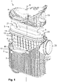
- a filter device 1 which is preferably used for gas filtration, in particular for air filtration in the intake tract of an internal combustion engine.
- the filter device 1 comprises a filter housing 2 which is composed of a basic filter housing 3 and a housing cover 4 , and a filter element 5 which can be inserted into the basic filter housing 3 .
- the housing cover 4 closes the receiving space in the filter base housing for receiving the filter element 5.
- the filter element 5 has a filter medium body 6 on which the filtration of the fluid to be cleaned takes place.
- the filter element 5 is designed as a round filter element, correspondingly the filter medium body 6 is also designed as a round element which encloses an internal flow space 7 into which the fluid to be cleaned is introduced.
- the fluid is introduced into the flow chamber 7 axially with respect to the longitudinal axis 8 of the filter element 5 and the filter device 1 .
- the fluid then flows through the wall of the filter medium body 6 radially from the inside to the outside. Accordingly, the inner wall of the filter medium body 6 forms the raw side and the outer wall the clean side.
- the filter element 5 and the filter medium body 6 have a strongly ovalized shape with two parallel longitudinal sides and semicircular narrow sides.
- the filter element 5 has a conical basic shape, in which the axially opposite end faces of the filter element 5 are of different sizes and have different outer circumferences.
- the axial end faces of the filter medium body 6 are each covered by an end disk 9, 10 in a flow-tight manner, with the end disk 9 being open on the larger end face of the filter element 5 is formed and has a flow opening 11 through which the raw fluid can flow into the internal flow space 7 .
- the opposite end plate 10, is designed to be closed, so that the inner flow chamber 7 is also closed axially on this side.
- Cams 12 are integrally formed on the closed end plate 10, which extend radially outwards and are positioned on the longitudinal sides adjacent to the narrow sides.
- a support grid 13 which is made in particular of plastic and is formed separately from the end plates 9 and 10 .
- the support grid 13 supports the filter medium body on its outer wall in the radial direction. Due to the radial flow through the filter medium body 6 from the inside to the outside, an outward pressure is produced in the filter medium body, which is absorbed by the support grid 13 . This ensures that the filter medium body 6 is not deformed by the pressure of the fluid flowing through it.
- a seal carrier 14 Adjacent to the end plate 9, in which the flow opening 11 for the introduction of the raw fluid is introduced, there is a seal carrier 14, which is the carrier of a sealing element 15.
- the seal carrier is designed as a ring-shaped peripheral carrier wall, which is preferably designed in one piece with the support grid 13 .
- the sealing element 15 is designed as a sealing ring, which is preferably inserted into a receiving groove in the end face of the support wall 14 on the side facing away from the adjacent end plate 9 .
- the sealing element 15 faces away from the end plate 9 and faces the opposite end plate 10 and, in the assembled state, rests on a circumferential shoulder 16 on the inner wall of the receiving filter base housing 3 .
- housing cover 4 there is a lateral flow opening 19 through which the raw fluid can flow radially into the filter device.
- the flow opening 19 in Housing cover 4 corresponds to a further flow opening 20 which is introduced into the basic filter housing 3 .
- the flow openings 19 and 20 lie one above the other, so that a continuous flow path is formed for the raw fluid.
- a recess 21 is introduced in the upper end plate 9, which is arranged adjacent to the ring-shaped peripheral seal carrier 14, in the region of the two opposite, semicircular narrow sides.
- This recess 21 allows a counter-positioning element 23 ( figure 5 , 6 ), which is located on the inside of the housing cover 4, in an associated positioning element 22 ( 3 , 4 ) to be inserted axially, the positioning element 22 being part of the filter element 5 .
- the positioning element 22 is designed as a wedge-shaped longitudinal body which extends radially inwards from the circumferential seal carrier 14 .
- the seal carrier 14 rests against the radial outside of the filter medium body 6, the wedge-shaped positioning element 22 protrudes, such as 3 can be seen, radially into the filter medium body 6, which is designed as a folded filter with a plurality of filter folds.
- the wedge-shaped positioning element 22 is designed as a hollow body, whereas the counter-positioning element 23 on the inside of the housing cover 4 is designed as a sword.
- the blade 23 protrudes into the hollow body 22, as a result of which the filter element 5 is centered in the filter housing 2. Due to the symmetrical design of the filter element 5 with recesses 21 and a positioning element 22 in the area of diametrically opposite, semicircular narrow sides, the filter element 5 can be inserted into the filter housing 2 in two different positions offset by 180°.
- the circumferential sealing element 15 rests on the internal shoulder 16 in the filter base housing 3 and ensures a flow-tight separation of the raw material from the clean side.
- the positioning element 22 has a base 24 in the form of a base plate ( 4 ), which is formed in one piece with the seal carrier 14 and extends radially inwards at the level of the plane of the seal carrier 14 in the interior cavity of the counter-positioning element 22 .
- the bottom 24 closes the internal cavity in the positioning element 22 so that no undesired flow of the fluid between the raw and clean side can occur via the positioning element 22 .
- the positioning element 22 on the inside of the support grid 13 extends axially over the entire height of the support grid.
- the seal carrier 14 is spaced axially from the upper end face of the end plate 9 . Also between the overhead edge of the positioning element 22 and the overhead end face of the end plate 9 there is an axial distance, so that the end plate 9, such as 1 and 2 to see, the positioning element 22 completely covers. Only via the recesses 21, which are introduced into the end plate 9, is there access to the positioning element 22, via which the sword-shaped counter-positioning element 23 can be inserted into the positioning element 22 when the cover 4 is put on.
- a flow guide element 17 on the inside of the housing cover 4 which is aligned with the counter-positioning element 23 .
- Both the counter-positioning element 23 and the flow guide element 17 are formed in a straight line and lie in one plane.
- the flow-guiding element 17 has a flow-guiding function for the untreated air that is brought in.
Landscapes
- Engineering & Computer Science (AREA)
- Chemical & Material Sciences (AREA)
- Chemical Kinetics & Catalysis (AREA)
- Combustion & Propulsion (AREA)
- Mechanical Engineering (AREA)
- General Engineering & Computer Science (AREA)
- Physics & Mathematics (AREA)
- Geometry (AREA)
- Manufacturing & Machinery (AREA)
- Filtering Of Dispersed Particles In Gases (AREA)
Applications Claiming Priority (3)
| Application Number | Priority Date | Filing Date | Title |
|---|---|---|---|
| DE102016012331.1A DE102016012331A1 (de) | 2016-10-17 | 2016-10-17 | Rundfilterelement, insbesondere zur Gasfiltration |
| EP17793591.3A EP3525913B1 (fr) | 2016-10-17 | 2017-10-17 | Élément filtrant rond, en particulier pour la filtration de gaz |
| PCT/EP2017/076395 WO2018073198A1 (fr) | 2016-10-17 | 2017-10-17 | Élément filtrant rond, en particulier pour la filtration de gaz |
Related Parent Applications (1)
| Application Number | Title | Priority Date | Filing Date |
|---|---|---|---|
| EP17793591.3A Division EP3525913B1 (fr) | 2016-10-17 | 2017-10-17 | Élément filtrant rond, en particulier pour la filtration de gaz |
Publications (1)
| Publication Number | Publication Date |
|---|---|
| EP3981494A1 true EP3981494A1 (fr) | 2022-04-13 |
Family
ID=60202019
Family Applications (2)
| Application Number | Title | Priority Date | Filing Date |
|---|---|---|---|
| EP17793591.3A Active EP3525913B1 (fr) | 2016-10-17 | 2017-10-17 | Élément filtrant rond, en particulier pour la filtration de gaz |
| EP21210689.2A Withdrawn EP3981494A1 (fr) | 2016-10-17 | 2017-10-17 | Élément filtrant rond, en particulier pour la filtration de gaz |
Family Applications Before (1)
| Application Number | Title | Priority Date | Filing Date |
|---|---|---|---|
| EP17793591.3A Active EP3525913B1 (fr) | 2016-10-17 | 2017-10-17 | Élément filtrant rond, en particulier pour la filtration de gaz |
Country Status (7)
| Country | Link |
|---|---|
| US (2) | US10946323B2 (fr) |
| EP (2) | EP3525913B1 (fr) |
| CN (1) | CN109843412B (fr) |
| DE (3) | DE102016012331A1 (fr) |
| ES (1) | ES2905700T3 (fr) |
| PL (1) | PL3525913T3 (fr) |
| WO (1) | WO2018073198A1 (fr) |
Families Citing this family (24)
| Publication number | Priority date | Publication date | Assignee | Title |
|---|---|---|---|---|
| CN107921342B (zh) * | 2015-08-24 | 2021-01-22 | 康明斯过滤Ip公司 | 空气过滤装置 |
| DE102016012331A1 (de) * | 2016-10-17 | 2018-04-19 | Mann + Hummel Gmbh | Rundfilterelement, insbesondere zur Gasfiltration |
| DE112018006269T5 (de) | 2017-12-08 | 2020-08-20 | Cummins Filtration Ip, Inc. | Ovale Dichtung mit Stabilisierungskontur |
| FR3078490B1 (fr) | 2018-03-05 | 2022-10-14 | Cummins Filtration Sarl | Element filtrant et boitier ayant des sections transversales non circulaires |
| DE112019002182B4 (de) | 2018-04-27 | 2024-01-11 | Mann+Hummel Gmbh | Rundfilterelement, insbesondere zur gasfiltration und filtereinrichtung |
| USD884866S1 (en) | 2018-05-08 | 2020-05-19 | Cummins Filtration Ip, Inc. | Filter element |
| US10918978B2 (en) | 2018-05-08 | 2021-02-16 | Cummins Filtration Ip, Inc. | Oval filter with exterior elliptical radial seal and internal support structure |
| MA52620A (fr) * | 2018-05-18 | 2021-05-26 | Mann & Hummel Gmbh | Élément filtrant, système de filtration équipé d'un élément filtrant et procédé |
| WO2019219657A1 (fr) * | 2018-05-18 | 2019-11-21 | Mann+Hummel Gmbh | Couvercle conçu pour un système de filtration, garniture d'étanchéité conçue pour un couvercle et système de filtration comportant un couvercle |
| PL3793711T3 (pl) * | 2018-05-18 | 2023-05-15 | Mann+Hummel Gmbh | Element filtrujący i system filtracyjny z elementem filtrującym oraz obudową |
| DE102019129691B4 (de) * | 2019-11-04 | 2022-01-05 | Elsässer Filtertechnik GmbH | Luftfilter mit Stützkranz und Filterelement zur Verwendung in einem Luftfilter |
| US11369908B2 (en) * | 2020-01-31 | 2022-06-28 | Pratt & Whitney Canada Corp. | Filter assembly for gas turbine engine |
| USD969289S1 (en) * | 2020-03-05 | 2022-11-08 | Cummins Filtration Inc. | Filter element |
| CN115397542B (zh) * | 2020-04-13 | 2025-04-11 | 康明斯过滤股份有限公司 | 利用卡口特征进行对准的一体化检修盖和过滤器元件 |
| DE102020116398B4 (de) * | 2020-06-22 | 2025-09-04 | Mann+Hummel Gmbh | Filterelement, Gehäuse für ein Filtersystem und Filtersystem mit einem Filterelement und einem Gehäuse |
| USD946733S1 (en) * | 2020-07-05 | 2022-03-22 | Champion Laboratories, Inc. | Filter frame |
| DE102020122027B4 (de) | 2020-08-24 | 2023-05-04 | Mann+Hummel Gmbh | Schalldämpfer und Filtersystem |
| DE102020122024A1 (de) | 2020-08-24 | 2022-02-24 | Mann+Hummel Gmbh | Filterelement und Filtersystem |
| US12161962B2 (en) * | 2020-10-28 | 2024-12-10 | Baldwin Filters, Inc. | Gasket and frame assembly for air filter |
| DE102023129023A1 (de) | 2023-10-23 | 2025-04-24 | Mann+Hummel Gmbh | Filterelement und Filtervorrichtung |
| DE102023129017A1 (de) | 2023-10-23 | 2025-04-24 | Mann+Hummel Gmbh | Ringfilterelementanordnung mit zwei rotatorisch zueinander ausgerichteten Ringfilterelementen |
| DE102023129022A1 (de) | 2023-10-23 | 2025-04-24 | Mann+Hummel Gmbh | Ringfilterelement mit radial innenliegender Eingriffskontur zur Winkelpositionierung |
| DE102023129015A1 (de) | 2023-10-23 | 2025-04-24 | Mann+Hummel Gmbh | Filterelement und Filtervorrichtung |
| DE102024130506A1 (de) * | 2024-10-21 | 2026-04-23 | Mann+Hummel Gmbh | Luftfilter mit einem radial in ein Gehäuse mit einer Filterpositioniereinrichtung einführbaren Filterelement |
Citations (5)
| Publication number | Priority date | Publication date | Assignee | Title |
|---|---|---|---|---|
| WO2006084282A2 (fr) * | 2005-02-04 | 2006-08-10 | Donaldson Company, Inc. | Separateur aerosol et procede correspondant |
| US20110132816A1 (en) * | 2004-12-24 | 2011-06-09 | Dan Vasilescu | Filter Provided with a Clogging Detector and an Assembly for Detecting the Presence of a Filtering Element Therein |
| EP2535550A2 (fr) * | 2011-06-17 | 2012-12-19 | MAHLE International GmbH | Elément de filtre annulaire |
| US20130232934A1 (en) | 2010-05-18 | 2013-09-12 | Donaldson Company Inc. | Air cleaner assemblies with filter element and method for installing the filter element |
| US20140208702A1 (en) * | 2011-06-30 | 2014-07-31 | Donaldson Company, Inc. | Air/oil separator assemblies; components; and methods |
Family Cites Families (6)
| Publication number | Priority date | Publication date | Assignee | Title |
|---|---|---|---|---|
| CN2683228Y (zh) * | 2003-11-20 | 2005-03-09 | 邸士第 | 净水器 |
| WO2008124437A2 (fr) * | 2007-04-03 | 2008-10-16 | Donaldson Company, Inc. | Épurateur d'air ; cartouche de filtre à air et procédé de fabrication |
| EP2878355B1 (fr) * | 2008-02-26 | 2018-06-27 | Mann + Hummel GmbH | Élément de filtre principal et dispositif de filtre, notamment filtre à air pour un moteur à combustion interne |
| US20100155321A1 (en) * | 2008-12-23 | 2010-06-24 | Sasur Timothy M | Filter assembly |
| DE102011011595A1 (de) * | 2011-02-17 | 2012-08-23 | Mann + Hummel Gmbh | Filterelement |
| DE102016012331A1 (de) * | 2016-10-17 | 2018-04-19 | Mann + Hummel Gmbh | Rundfilterelement, insbesondere zur Gasfiltration |
-
2016
- 2016-10-17 DE DE102016012331.1A patent/DE102016012331A1/de not_active Withdrawn
-
2017
- 2017-10-17 DE DE112017005239.4T patent/DE112017005239A5/de active Pending
- 2017-10-17 DE DE202017006783.8U patent/DE202017006783U1/de active Active
- 2017-10-17 EP EP17793591.3A patent/EP3525913B1/fr active Active
- 2017-10-17 CN CN201780064212.8A patent/CN109843412B/zh active Active
- 2017-10-17 ES ES17793591T patent/ES2905700T3/es active Active
- 2017-10-17 PL PL17793591T patent/PL3525913T3/pl unknown
- 2017-10-17 WO PCT/EP2017/076395 patent/WO2018073198A1/fr not_active Ceased
- 2017-10-17 EP EP21210689.2A patent/EP3981494A1/fr not_active Withdrawn
-
2019
- 2019-04-17 US US16/386,366 patent/US10946323B2/en active Active
-
2021
- 2021-02-09 US US17/171,733 patent/US11633686B2/en active Active
Patent Citations (5)
| Publication number | Priority date | Publication date | Assignee | Title |
|---|---|---|---|---|
| US20110132816A1 (en) * | 2004-12-24 | 2011-06-09 | Dan Vasilescu | Filter Provided with a Clogging Detector and an Assembly for Detecting the Presence of a Filtering Element Therein |
| WO2006084282A2 (fr) * | 2005-02-04 | 2006-08-10 | Donaldson Company, Inc. | Separateur aerosol et procede correspondant |
| US20130232934A1 (en) | 2010-05-18 | 2013-09-12 | Donaldson Company Inc. | Air cleaner assemblies with filter element and method for installing the filter element |
| EP2535550A2 (fr) * | 2011-06-17 | 2012-12-19 | MAHLE International GmbH | Elément de filtre annulaire |
| US20140208702A1 (en) * | 2011-06-30 | 2014-07-31 | Donaldson Company, Inc. | Air/oil separator assemblies; components; and methods |
Also Published As
| Publication number | Publication date |
|---|---|
| DE102016012331A1 (de) | 2018-04-19 |
| US10946323B2 (en) | 2021-03-16 |
| DE202017006783U1 (de) | 2018-05-22 |
| WO2018073198A1 (fr) | 2018-04-26 |
| CN109843412A (zh) | 2019-06-04 |
| EP3525913A1 (fr) | 2019-08-21 |
| US20190308125A1 (en) | 2019-10-10 |
| EP3525913B1 (fr) | 2021-12-22 |
| ES2905700T3 (es) | 2022-04-11 |
| CN109843412B (zh) | 2021-11-16 |
| US20210229017A1 (en) | 2021-07-29 |
| US11633686B2 (en) | 2023-04-25 |
| PL3525913T3 (pl) | 2022-04-25 |
| BR112019005023A2 (pt) | 2019-06-18 |
| DE112017005239A5 (de) | 2019-06-27 |
Similar Documents
| Publication | Publication Date | Title |
|---|---|---|
| EP3525913B1 (fr) | Élément filtrant rond, en particulier pour la filtration de gaz | |
| EP3854470B1 (fr) | Installation de filtre et élément de filtre rond, en particulier pour la filtration de gaz | |
| EP3525911B1 (fr) | Élément filtre rond, en particulier pour la filtration de gaz | |
| EP3795233B1 (fr) | Élément de filtre à air | |
| DE102016012328B4 (de) | Filtereinrichtung mit einem Rundfilterelement, insbesondere zur Gasfiltration | |
| DE102014006852B4 (de) | Hohlfilterelement, Filtergehäuse und Filter | |
| EP3793711B1 (fr) | Élément filtrant et système de filtration équipé d'un élément filtrant et d'un boîtier | |
| EP3452205B1 (fr) | Élément filtrant, en particulier pour la filtration de gaz, et dispositif de filtration | |
| EP3157652A2 (fr) | Filtre et cartouche filtrante | |
| EP3793712B1 (fr) | Élément filtrant, système de filtration équipé d'un élément filtrant et procédé | |
| WO2008037448A1 (fr) | Cartouche filtrante annulaire pour filtre | |
| DE102016005352A1 (de) | Ringförmiges Filterelement, insbesondere zur Gasfiltration | |
| EP4037803B1 (fr) | Filtre à liquide et élément d'égalisation de volume pour un filtre à liquide | |
| EP4168155A1 (fr) | Élément filtrant, boîtier pour un système de filtrage et système de filtrage comprenant un élément filtrant et un boîtier | |
| WO2017144287A1 (fr) | Élément filtrant, en particulier pour la filtration de gaz | |
| EP3297745B1 (fr) | Élément filtrant, en particulier pour la filtration de gaz | |
| DE102013004865A1 (de) | Filtereinrichtung mit einem ringförmigen Filterelement | |
| WO2019207024A1 (fr) | Élément filtrant rond, en particulier destinée à la filtration de gaz | |
| DE102018120329A1 (de) | Filterelement und Filtersystem mit einem Filterelement | |
| DE102014017024A1 (de) | Filtereinrichtung | |
| WO2025228621A1 (fr) | Élément filtrant rond, en particulier pour la filtration de gaz | |
| DE202013011203U1 (de) | Filtereinrichtung | |
| WO2015007500A1 (fr) | Dispositif filtrant |
Legal Events
| Date | Code | Title | Description |
|---|---|---|---|
| PUAI | Public reference made under article 153(3) epc to a published international application that has entered the european phase |
Free format text: ORIGINAL CODE: 0009012 |
|
| STAA | Information on the status of an ep patent application or granted ep patent |
Free format text: STATUS: THE APPLICATION HAS BEEN PUBLISHED |
|
| AC | Divisional application: reference to earlier application |
Ref document number: 3525913 Country of ref document: EP Kind code of ref document: P |
|
| AK | Designated contracting states |
Kind code of ref document: A1 Designated state(s): AL AT BE BG CH CY CZ DE DK EE ES FI FR GB GR HR HU IE IS IT LI LT LU LV MC MK MT NL NO PL PT RO RS SE SI SK SM TR |
|
| STAA | Information on the status of an ep patent application or granted ep patent |
Free format text: STATUS: THE APPLICATION IS DEEMED TO BE WITHDRAWN |
|
| 18D | Application deemed to be withdrawn |
Effective date: 20221014 |