EP3981602A1 - Druckgerät und -methode - Google Patents
Druckgerät und -methode Download PDFInfo
- Publication number
- EP3981602A1 EP3981602A1 EP21202007.7A EP21202007A EP3981602A1 EP 3981602 A1 EP3981602 A1 EP 3981602A1 EP 21202007 A EP21202007 A EP 21202007A EP 3981602 A1 EP3981602 A1 EP 3981602A1
- Authority
- EP
- European Patent Office
- Prior art keywords
- fluid
- fluid distribution
- inkjet printhead
- array
- shows
- Prior art date
- Legal status (The legal status is an assumption and is not a legal conclusion. Google has not performed a legal analysis and makes no representation as to the accuracy of the status listed.)
- Pending
Links
- 238000007639 printing Methods 0.000 title claims description 32
- 238000000034 method Methods 0.000 title description 34
- 239000012530 fluid Substances 0.000 claims abstract description 386
- 238000009826 distribution Methods 0.000 claims abstract description 186
- 238000005086 pumping Methods 0.000 claims description 191
- 230000001419 dependent effect Effects 0.000 claims description 7
- 239000000758 substrate Substances 0.000 description 88
- 239000000976 ink Substances 0.000 description 54
- 235000012431 wafers Nutrition 0.000 description 51
- 238000010304 firing Methods 0.000 description 34
- 239000003351 stiffener Substances 0.000 description 32
- 239000000463 material Substances 0.000 description 29
- 238000007747 plating Methods 0.000 description 27
- 230000008569 process Effects 0.000 description 27
- 239000011521 glass Substances 0.000 description 26
- 239000000853 adhesive Substances 0.000 description 25
- 230000001070 adhesive effect Effects 0.000 description 25
- 238000004891 communication Methods 0.000 description 23
- 230000005684 electric field Effects 0.000 description 22
- 239000011295 pitch Substances 0.000 description 21
- 238000004519 manufacturing process Methods 0.000 description 18
- 239000000919 ceramic Substances 0.000 description 14
- 239000003292 glue Substances 0.000 description 14
- 238000000576 coating method Methods 0.000 description 12
- 239000011248 coating agent Substances 0.000 description 11
- 238000000151 deposition Methods 0.000 description 10
- 230000008021 deposition Effects 0.000 description 10
- 238000005516 engineering process Methods 0.000 description 10
- 238000002955 isolation Methods 0.000 description 10
- 230000008859 change Effects 0.000 description 9
- 230000006870 function Effects 0.000 description 9
- 230000003287 optical effect Effects 0.000 description 9
- 238000000429 assembly Methods 0.000 description 8
- 230000007935 neutral effect Effects 0.000 description 8
- 238000003848 UV Light-Curing Methods 0.000 description 7
- 238000003491 array Methods 0.000 description 7
- 238000013016 damping Methods 0.000 description 7
- 238000013461 design Methods 0.000 description 7
- 230000000712 assembly Effects 0.000 description 6
- 230000000694 effects Effects 0.000 description 6
- 230000013011 mating Effects 0.000 description 6
- 239000002245 particle Substances 0.000 description 6
- 229910002056 binary alloy Inorganic materials 0.000 description 5
- 229910010293 ceramic material Inorganic materials 0.000 description 5
- 238000010329 laser etching Methods 0.000 description 5
- 239000007787 solid Substances 0.000 description 5
- 239000004593 Epoxy Substances 0.000 description 4
- 239000006098 acoustic absorber Substances 0.000 description 4
- 230000001154 acute effect Effects 0.000 description 4
- 230000015572 biosynthetic process Effects 0.000 description 4
- 239000003086 colorant Substances 0.000 description 4
- 239000004020 conductor Substances 0.000 description 4
- 239000010408 film Substances 0.000 description 4
- 229910052751 metal Inorganic materials 0.000 description 4
- 239000002184 metal Substances 0.000 description 4
- 239000004005 microsphere Substances 0.000 description 4
- 230000009467 reduction Effects 0.000 description 4
- VYPSYNLAJGMNEJ-UHFFFAOYSA-N Silicium dioxide Chemical compound O=[Si]=O VYPSYNLAJGMNEJ-UHFFFAOYSA-N 0.000 description 3
- 238000013459 approach Methods 0.000 description 3
- 230000008901 benefit Effects 0.000 description 3
- 239000005388 borosilicate glass Substances 0.000 description 3
- 238000007641 inkjet printing Methods 0.000 description 3
- 238000007689 inspection Methods 0.000 description 3
- 239000011810 insulating material Substances 0.000 description 3
- 238000005304 joining Methods 0.000 description 3
- 230000002045 lasting effect Effects 0.000 description 3
- 238000012545 processing Methods 0.000 description 3
- RTAQQCXQSZGOHL-UHFFFAOYSA-N Titanium Chemical compound [Ti] RTAQQCXQSZGOHL-UHFFFAOYSA-N 0.000 description 2
- QCWXUUIWCKQGHC-UHFFFAOYSA-N Zirconium Chemical compound [Zr] QCWXUUIWCKQGHC-UHFFFAOYSA-N 0.000 description 2
- 239000011149 active material Substances 0.000 description 2
- 230000009286 beneficial effect Effects 0.000 description 2
- 238000010276 construction Methods 0.000 description 2
- 238000001816 cooling Methods 0.000 description 2
- 238000010586 diagram Methods 0.000 description 2
- 125000003700 epoxy group Chemical group 0.000 description 2
- 239000005357 flat glass Substances 0.000 description 2
- 238000010438 heat treatment Methods 0.000 description 2
- 230000006872 improvement Effects 0.000 description 2
- 230000010354 integration Effects 0.000 description 2
- 238000000059 patterning Methods 0.000 description 2
- 230000000737 periodic effect Effects 0.000 description 2
- 229920000052 poly(p-xylylene) Polymers 0.000 description 2
- 229920000647 polyepoxide Polymers 0.000 description 2
- 238000000926 separation method Methods 0.000 description 2
- 125000006850 spacer group Chemical group 0.000 description 2
- 230000001360 synchronised effect Effects 0.000 description 2
- 238000012360 testing method Methods 0.000 description 2
- 238000011144 upstream manufacturing Methods 0.000 description 2
- 229910052726 zirconium Inorganic materials 0.000 description 2
- UFHFLCQGNIYNRP-UHFFFAOYSA-N Hydrogen Chemical compound [H][H] UFHFLCQGNIYNRP-UHFFFAOYSA-N 0.000 description 1
- XUIMIQQOPSSXEZ-UHFFFAOYSA-N Silicon Chemical compound [Si] XUIMIQQOPSSXEZ-UHFFFAOYSA-N 0.000 description 1
- 238000010521 absorption reaction Methods 0.000 description 1
- 230000001133 acceleration Effects 0.000 description 1
- 230000009471 action Effects 0.000 description 1
- 239000000654 additive Substances 0.000 description 1
- 230000000996 additive effect Effects 0.000 description 1
- 239000006117 anti-reflective coating Substances 0.000 description 1
- QVGXLLKOCUKJST-UHFFFAOYSA-N atomic oxygen Chemical compound [O] QVGXLLKOCUKJST-UHFFFAOYSA-N 0.000 description 1
- 230000004888 barrier function Effects 0.000 description 1
- 230000000903 blocking effect Effects 0.000 description 1
- 238000009835 boiling Methods 0.000 description 1
- 230000008878 coupling Effects 0.000 description 1
- 238000010168 coupling process Methods 0.000 description 1
- 238000005859 coupling reaction Methods 0.000 description 1
- 238000001723 curing Methods 0.000 description 1
- 230000003111 delayed effect Effects 0.000 description 1
- 239000010432 diamond Substances 0.000 description 1
- 238000006073 displacement reaction Methods 0.000 description 1
- 239000012777 electrically insulating material Substances 0.000 description 1
- 238000005868 electrolysis reaction Methods 0.000 description 1
- 229920006332 epoxy adhesive Polymers 0.000 description 1
- -1 flex Substances 0.000 description 1
- 239000011888 foil Substances 0.000 description 1
- 238000009472 formulation Methods 0.000 description 1
- 238000007710 freezing Methods 0.000 description 1
- 230000008014 freezing Effects 0.000 description 1
- 239000001257 hydrogen Substances 0.000 description 1
- 229910052739 hydrogen Inorganic materials 0.000 description 1
- 230000003116 impacting effect Effects 0.000 description 1
- 238000003780 insertion Methods 0.000 description 1
- 230000037431 insertion Effects 0.000 description 1
- 238000009413 insulation Methods 0.000 description 1
- 238000003754 machining Methods 0.000 description 1
- 239000011159 matrix material Substances 0.000 description 1
- 230000007246 mechanism Effects 0.000 description 1
- 239000012528 membrane Substances 0.000 description 1
- 239000003595 mist Substances 0.000 description 1
- 239000000203 mixture Substances 0.000 description 1
- 230000010355 oscillation Effects 0.000 description 1
- 239000001301 oxygen Substances 0.000 description 1
- 229910052760 oxygen Inorganic materials 0.000 description 1
- 230000037361 pathway Effects 0.000 description 1
- 230000000704 physical effect Effects 0.000 description 1
- 239000000049 pigment Substances 0.000 description 1
- 238000003825 pressing Methods 0.000 description 1
- 230000002035 prolonged effect Effects 0.000 description 1
- 230000001681 protective effect Effects 0.000 description 1
- 230000003134 recirculating effect Effects 0.000 description 1
- 230000001105 regulatory effect Effects 0.000 description 1
- 229920005989 resin Polymers 0.000 description 1
- 239000011347 resin Substances 0.000 description 1
- 230000004044 response Effects 0.000 description 1
- 230000002441 reversible effect Effects 0.000 description 1
- 230000000630 rising effect Effects 0.000 description 1
- 239000004576 sand Substances 0.000 description 1
- 238000007789 sealing Methods 0.000 description 1
- 239000005368 silicate glass Substances 0.000 description 1
- 229910052710 silicon Inorganic materials 0.000 description 1
- 239000010703 silicon Substances 0.000 description 1
- 235000012239 silicon dioxide Nutrition 0.000 description 1
- 239000000377 silicon dioxide Substances 0.000 description 1
- 238000001228 spectrum Methods 0.000 description 1
- 239000012798 spherical particle Substances 0.000 description 1
- 239000007921 spray Substances 0.000 description 1
- 238000004544 sputter deposition Methods 0.000 description 1
- 239000000725 suspension Substances 0.000 description 1
- 230000009897 systematic effect Effects 0.000 description 1
- 239000010409 thin film Substances 0.000 description 1
- 230000026683 transduction Effects 0.000 description 1
- 238000010361 transduction Methods 0.000 description 1
- 230000001052 transient effect Effects 0.000 description 1
- 238000001771 vacuum deposition Methods 0.000 description 1
- 239000002918 waste heat Substances 0.000 description 1
- XLYOFNOQVPJJNP-UHFFFAOYSA-N water Substances O XLYOFNOQVPJJNP-UHFFFAOYSA-N 0.000 description 1
Images


Classifications
-
- B—PERFORMING OPERATIONS; TRANSPORTING
- B41—PRINTING; LINING MACHINES; TYPEWRITERS; STAMPS
- B41J—TYPEWRITERS; SELECTIVE PRINTING MECHANISMS, i.e. MECHANISMS PRINTING OTHERWISE THAN FROM A FORME; CORRECTION OF TYPOGRAPHICAL ERRORS
- B41J2/00—Typewriters or selective printing mechanisms characterised by the printing or marking process for which they are designed
- B41J2/005—Typewriters or selective printing mechanisms characterised by the printing or marking process for which they are designed characterised by bringing liquid or particles selectively into contact with a printing material
- B41J2/01—Ink jet
- B41J2/135—Nozzles
- B41J2/14—Structure thereof only for on-demand ink jet heads
- B41J2/14201—Structure of print heads with piezoelectric elements
- B41J2/14209—Structure of print heads with piezoelectric elements of finger type, chamber walls consisting integrally of piezoelectric material
-
- B—PERFORMING OPERATIONS; TRANSPORTING
- B41—PRINTING; LINING MACHINES; TYPEWRITERS; STAMPS
- B41J—TYPEWRITERS; SELECTIVE PRINTING MECHANISMS, i.e. MECHANISMS PRINTING OTHERWISE THAN FROM A FORME; CORRECTION OF TYPOGRAPHICAL ERRORS
- B41J2/00—Typewriters or selective printing mechanisms characterised by the printing or marking process for which they are designed
- B41J2/005—Typewriters or selective printing mechanisms characterised by the printing or marking process for which they are designed characterised by bringing liquid or particles selectively into contact with a printing material
- B41J2/01—Ink jet
- B41J2/135—Nozzles
- B41J2/14—Structure thereof only for on-demand ink jet heads
- B41J2/14016—Structure of bubble jet print heads
- B41J2/14072—Electrical connections, e.g. details on electrodes, connecting the chip to the outside...
-
- B—PERFORMING OPERATIONS; TRANSPORTING
- B41—PRINTING; LINING MACHINES; TYPEWRITERS; STAMPS
- B41J—TYPEWRITERS; SELECTIVE PRINTING MECHANISMS, i.e. MECHANISMS PRINTING OTHERWISE THAN FROM A FORME; CORRECTION OF TYPOGRAPHICAL ERRORS
- B41J2/00—Typewriters or selective printing mechanisms characterised by the printing or marking process for which they are designed
- B41J2/005—Typewriters or selective printing mechanisms characterised by the printing or marking process for which they are designed characterised by bringing liquid or particles selectively into contact with a printing material
- B41J2/01—Ink jet
- B41J2/135—Nozzles
- B41J2/14—Structure thereof only for on-demand ink jet heads
- B41J2/14201—Structure of print heads with piezoelectric elements
-
- B—PERFORMING OPERATIONS; TRANSPORTING
- B41—PRINTING; LINING MACHINES; TYPEWRITERS; STAMPS
- B41J—TYPEWRITERS; SELECTIVE PRINTING MECHANISMS, i.e. MECHANISMS PRINTING OTHERWISE THAN FROM A FORME; CORRECTION OF TYPOGRAPHICAL ERRORS
- B41J2/00—Typewriters or selective printing mechanisms characterised by the printing or marking process for which they are designed
- B41J2/005—Typewriters or selective printing mechanisms characterised by the printing or marking process for which they are designed characterised by bringing liquid or particles selectively into contact with a printing material
- B41J2/01—Ink jet
- B41J2/135—Nozzles
- B41J2/14—Structure thereof only for on-demand ink jet heads
- B41J2/1433—Structure of nozzle plates
-
- B—PERFORMING OPERATIONS; TRANSPORTING
- B41—PRINTING; LINING MACHINES; TYPEWRITERS; STAMPS
- B41J—TYPEWRITERS; SELECTIVE PRINTING MECHANISMS, i.e. MECHANISMS PRINTING OTHERWISE THAN FROM A FORME; CORRECTION OF TYPOGRAPHICAL ERRORS
- B41J2/00—Typewriters or selective printing mechanisms characterised by the printing or marking process for which they are designed
- B41J2/005—Typewriters or selective printing mechanisms characterised by the printing or marking process for which they are designed characterised by bringing liquid or particles selectively into contact with a printing material
- B41J2/01—Ink jet
- B41J2/135—Nozzles
- B41J2/16—Production of nozzles
- B41J2/1601—Production of bubble jet print heads
- B41J2/1604—Production of bubble jet print heads of the edge shooter type
-
- B—PERFORMING OPERATIONS; TRANSPORTING
- B41—PRINTING; LINING MACHINES; TYPEWRITERS; STAMPS
- B41J—TYPEWRITERS; SELECTIVE PRINTING MECHANISMS, i.e. MECHANISMS PRINTING OTHERWISE THAN FROM A FORME; CORRECTION OF TYPOGRAPHICAL ERRORS
- B41J2/00—Typewriters or selective printing mechanisms characterised by the printing or marking process for which they are designed
- B41J2/005—Typewriters or selective printing mechanisms characterised by the printing or marking process for which they are designed characterised by bringing liquid or particles selectively into contact with a printing material
- B41J2/01—Ink jet
- B41J2/135—Nozzles
- B41J2/16—Production of nozzles
- B41J2/1607—Production of print heads with piezoelectric elements
- B41J2/1609—Production of print heads with piezoelectric elements of finger type, chamber walls consisting integrally of piezoelectric material
-
- B—PERFORMING OPERATIONS; TRANSPORTING
- B41—PRINTING; LINING MACHINES; TYPEWRITERS; STAMPS
- B41J—TYPEWRITERS; SELECTIVE PRINTING MECHANISMS, i.e. MECHANISMS PRINTING OTHERWISE THAN FROM A FORME; CORRECTION OF TYPOGRAPHICAL ERRORS
- B41J25/00—Actions or mechanisms not otherwise provided for
- B41J25/001—Mechanisms for bodily moving print heads or carriages parallel to the paper surface
- B41J25/003—Mechanisms for bodily moving print heads or carriages parallel to the paper surface for changing the angle between a print element array axis and the printing line, e.g. for dot density changes
-
- B—PERFORMING OPERATIONS; TRANSPORTING
- B41—PRINTING; LINING MACHINES; TYPEWRITERS; STAMPS
- B41J—TYPEWRITERS; SELECTIVE PRINTING MECHANISMS, i.e. MECHANISMS PRINTING OTHERWISE THAN FROM A FORME; CORRECTION OF TYPOGRAPHICAL ERRORS
- B41J2/00—Typewriters or selective printing mechanisms characterised by the printing or marking process for which they are designed
- B41J2/005—Typewriters or selective printing mechanisms characterised by the printing or marking process for which they are designed characterised by bringing liquid or particles selectively into contact with a printing material
- B41J2/01—Ink jet
- B41J2/135—Nozzles
- B41J2/14—Structure thereof only for on-demand ink jet heads
- B41J2002/14379—Edge shooter
-
- B—PERFORMING OPERATIONS; TRANSPORTING
- B41—PRINTING; LINING MACHINES; TYPEWRITERS; STAMPS
- B41J—TYPEWRITERS; SELECTIVE PRINTING MECHANISMS, i.e. MECHANISMS PRINTING OTHERWISE THAN FROM A FORME; CORRECTION OF TYPOGRAPHICAL ERRORS
- B41J2/00—Typewriters or selective printing mechanisms characterised by the printing or marking process for which they are designed
- B41J2/005—Typewriters or selective printing mechanisms characterised by the printing or marking process for which they are designed characterised by bringing liquid or particles selectively into contact with a printing material
- B41J2/01—Ink jet
- B41J2/135—Nozzles
- B41J2/14—Structure thereof only for on-demand ink jet heads
- B41J2002/14419—Manifold
-
- B—PERFORMING OPERATIONS; TRANSPORTING
- B41—PRINTING; LINING MACHINES; TYPEWRITERS; STAMPS
- B41J—TYPEWRITERS; SELECTIVE PRINTING MECHANISMS, i.e. MECHANISMS PRINTING OTHERWISE THAN FROM A FORME; CORRECTION OF TYPOGRAPHICAL ERRORS
- B41J2/00—Typewriters or selective printing mechanisms characterised by the printing or marking process for which they are designed
- B41J2/005—Typewriters or selective printing mechanisms characterised by the printing or marking process for which they are designed characterised by bringing liquid or particles selectively into contact with a printing material
- B41J2/01—Ink jet
- B41J2/135—Nozzles
- B41J2/14—Structure thereof only for on-demand ink jet heads
- B41J2002/14491—Electrical connection
-
- B—PERFORMING OPERATIONS; TRANSPORTING
- B41—PRINTING; LINING MACHINES; TYPEWRITERS; STAMPS
- B41J—TYPEWRITERS; SELECTIVE PRINTING MECHANISMS, i.e. MECHANISMS PRINTING OTHERWISE THAN FROM A FORME; CORRECTION OF TYPOGRAPHICAL ERRORS
- B41J2202/00—Embodiments of or processes related to ink-jet or thermal heads
- B41J2202/01—Embodiments of or processes related to ink-jet heads
- B41J2202/12—Embodiments of or processes related to ink-jet heads with ink circulating through the whole print head
-
- B—PERFORMING OPERATIONS; TRANSPORTING
- B41—PRINTING; LINING MACHINES; TYPEWRITERS; STAMPS
- B41J—TYPEWRITERS; SELECTIVE PRINTING MECHANISMS, i.e. MECHANISMS PRINTING OTHERWISE THAN FROM A FORME; CORRECTION OF TYPOGRAPHICAL ERRORS
- B41J2202/00—Embodiments of or processes related to ink-jet or thermal heads
- B41J2202/01—Embodiments of or processes related to ink-jet heads
- B41J2202/19—Assembling head units
-
- B—PERFORMING OPERATIONS; TRANSPORTING
- B41—PRINTING; LINING MACHINES; TYPEWRITERS; STAMPS
- B41J—TYPEWRITERS; SELECTIVE PRINTING MECHANISMS, i.e. MECHANISMS PRINTING OTHERWISE THAN FROM A FORME; CORRECTION OF TYPOGRAPHICAL ERRORS
- B41J2202/00—Embodiments of or processes related to ink-jet or thermal heads
- B41J2202/01—Embodiments of or processes related to ink-jet heads
- B41J2202/20—Modules
Definitions
- the present invention relates to inkjet printing. More specifically, the present invention relates to piezoelectric inkjet printing apparatus and methods.
- Piezoelectric printheads are typically comprised of a piezoelectric disc, coaxially arranged with an ink filled conical nozzle.
- the piezoelectric unit converts electrical driving voltage into mechanical deformation of a segment of the ink chamber, which generates the requisite pressure for drop formation.
- Pressure waves in the printing fluid caused by the mechanical deformation cause spray of ink drops from the nozzle.
- the ink channel structure and the driving pulse are designed to obtain a large incoming positive pressure peak at the printhead nozzle, thus driving ink through the nozzle.
- the ink channel is enclosed in a hollow tube of piezoelectric material arranged to squeeze the ink chamber when a voltage is applied to it.
- Alternative arrangements include those in which a segment of the ink chamber wall is formed of a diaphragm with a piezoelectric material bonded thereto; when voltage is applied to the piezoelectric material, the diaphragm is manipulated to eject the requisite ink drops via the nozzle.
- a flat disc of piezoelectric material is bonded to a passive membrane and manipulated to deform a rear wall or roof of the ink chamber.
- the electric field is applied in the polarisation direction of the piezoelectric material, causing deformation perpendicular to the poling direction.
- a piezoelectric element is arranged to push against the ink chamber wall.
- the electrical field is applied in the poling direction of the material to produce deformation either parallel or perpendicular to the poling direction.
- a printhead will usually consist of several nozzles in an array, each is driven by a piezoelectric actuator element.
- a voltage is applied to the piezoelectric material causing the material to deform a cross section of the ink channel using an inverse piezoelectric effect.
- the resultant pressure waves propagate along the channel direction.
- the negative pressure is subsequently reflected back from the reservoir to become a positive pressure wave in the channel, which is amplified to create a large positive pressure peak at the nozzle, causing drop firing.
- the acceleration of ink movement in the small cross sectional area of the nozzle relative the reservoir results in drop formation, subject to fluid properties.
- the commercial market for piezoelectric inkjet technology is dominated by two types of technology; bulk piezoelectric technology (bulk PZT) providing 150 - 600 dot per inch (dpi) resolution delivered at medium to high speed, and micro electro-mechanical systems (MEMS) based technology providing 600 - 1200 dpi resolution at medium speed.
- bulk piezoelectric technology providing 150 - 600 dot per inch (dpi) resolution delivered at medium to high speed
- MEMS micro electro-mechanical systems
- the pixel on the printed substrate should be sized according to the intended viewing distance, and consequently, the larger the viewing distance, the larger the pixel size can be before the viewer's eye can detect the individual pixels.
- a higher pixel resolution can mean more nozzles, which implies a higher cost and a slower output.
- the present invention therefore provides an inkjet printhead as set out in the claims.
- an inkjet printhead comprising a lamellar structure made up of vertically-oriented layers, the layers including a fluid distribution channel adapted to convey fluid in a vertical direction within the layer, an actuator module adapted to expel ink droplets from the layer in a downward direction.
- the inkjet printhead can be configured such that the fluid distribution channel and the actuator module are provided in separate layers.
- the inkjet printhead can be configured such that alternate fluid distribution channel layers and actuator module layers.
- the inkjet printhead can be configured such that the fluid distribution channel layers and actuator module layers are adjacent.
- the inkjet printhead can be configured such that the fluid distribution channel and the actuator module each include two aligned fluid conduits extending horizontally through the layer, thereby to define a pair of reservoirs.
- the inkjet printhead can be configured such that the ink conduits are located in the upper region of the layers.
- the inkjet printhead can be configured such that the fluid distribution channel extends between one of the ink conduits and a lower edge of the actuator module.
- the inkjet printhead can be configured such that the fluid distribution channel is bounded to its front and rear directions by walls formed in the fluid distribution channel layer.
- the inkjet printhead can be configured such that the fluid distribution channel is bounded to at least one lateral side by an adjacent layer.
- the inkjet printhead can be configured such that one of the adjacent layers is the actuator module layer.
- the inkjet printhead can be configured such that a means for supplying fluid under pressure to one of the ink conduits is included.
- the inkjet printhead can be configured such that an outlet is provided to permit excess fluid to drain from the other ink conduit.
- the inkjet printhead can be configured such that the actuator modules comprise electronic control circuitry, located within the layer closer to one surface than the other, and are oriented so that the one surface is adjacent a fluid distribution channel that communicates with the other ink conduit.
- the inkjet printhead can be configured such that a nozzle plate is located beneath the lamellar structure, the nozzle plate including a plurality of through-holes, each aligned with an actuator module.
- the inkjet printhead can be configured such that the through-holes of the nozzle plate are arranged in a plurality of rows, each row being located beneath an actuator module.
- the inkjet printhead can be configured such that as dependent the fluid distribution channel is bounded on its lower edge by the nozzle plate.
- the inkjet printhead can be configured such that the layers are a substantially flat, parallel sided sheet of insulating material.
- the inkjet printhead can be configured such that the layers are formed of a material selected from the group consisting of ceramic, glass, silicate glass and polymeric materials.
- the inkjet printhead a can be configured such that elements of the printhead are bonded together with a UV-curing epoxy adhesive.
- the inkjet printhead can be configured such that the actuator module is a layer comprising a linear array of fluid pumping chambers along its lower edge, a pair of substantially parallel faceplates, wherein one of the faceplates carries control circuitry for the fluid pumping chambers and has conductive tracks on a surface leading from the upper edge of the module to the control circuitry and from the control circuitry to the fluid pumping chambers, and the control circuitry and the conductive tracks are on an inner side of the faceplate.
- the inkjet printhead can be configured such that the array of fluid pumping chambers is sandwiched between the faceplates.
- the inkjet printhead can be configured such that the actuator module is sandwiched between a first fluid distribution channel which conveys fluid downwardly towards the array of ink pumping chambers and a second fluid distribution channel which conveys ink upwardly from the array of ink pumping chambers, and the faceplate carrying the control circuitry is on the side of the actuator module adjacent the second fluid distribution channel.
- the inkjet printhead can be configured such that a spacer comprises a recess to accommodate the control circuitry.
- the inkjet printhead can be configured such that the two fluid conduits are defined by aligned apertures in the layers making up the lamellar structure.
- An inkjet printhead can be configured such that the two fluid conduits are located within each layer at a location which is symmetric under a half-rotation about a vertical axis in the plane of the layers, the fluid distribution channel layers are identical in structure, and include a channel which communicates with one fluid conduit and not the other and leads to the lower edge of the layer, and alternate fluid distribution channel layers in the lamellar structure are oriented oppositely so as to communicate with different fluid conduits.
- the inkjet printhead can be configured such that, within the lamellar structure located between actuator modules, a structure interposed between neighbouring actuator modules of a flexible material.
- the inkjet printhead can be configured such that, within the lamellar structure located between actuator modules, a structure interposed between neighbouring actuator modules having a wedge-shaped profile with an oblique edge of the wedge facing the actuator module.
- the inkjet printhead can be configured such that the structure is of a flexible material.
- the inkjet printhead can be configured such that the structure is hollow.
- a droplet deposition apparatus comprising a transducer strip having two sides parallel to each other being a first side and a second side and a top face perpendicular to said sides, comprising a plurality of walls and channels, forming a plurality of pumping chambers, each pumping chamber having a first port disposed on the first side; a second port disposed on the second side; all of or a proportion of said pumping chambers having a third port disposed on the top face; and in fluid communication with a nozzle for droplet ejection therefrom, and a structure formed of one or more layers of a piezo-electrically active material comprising: an array of functionally independent sub-modules each capable of applying pressure pulses to fluid therein, each comprising: a common channel; and two walls; and two isolated half-channels; and a cover component joined to the tops of the walls to form a pumping chamber closed on four sides and open on two sides; and a substrate
- the droplet deposition apparatus can be configured such that electrical circuit elements on the base of the channel electrically join second and third common wall electrodes.
- the droplet deposition apparatus can be configured such that electrical circuit elements on the first or second sides of the transducer strip electrically join second and third common wall electrodes.
- the droplet deposition apparatus can be configured such that electrical circuit elements on the first or second aperture plate electrically join second and third common wall electrodes.
- the droplet deposition apparatus can be configured such that said piezoelectrically active material is formed of two layers of PZT joined together.
- the droplet deposition apparatus a can be configured such that interfacing isolated half-channels from neighbouring common channels are joined to a single isolated pumping chamber forming an array of alternating common and isolated pumping chambers.
- the droplet deposition apparatus can be configured such that said isolated pumping chambers have equal or smaller width than said common pumping chambers.
- the droplet deposition apparatus can be configured such that said first, second, third and fourth electrodes are formed by a vacuum sputtering process covering all of the walls and the bottoms of the pumping chambers.
- the droplet deposition apparatus can be configured such that additional grooves are cut into the bottoms of alternate pumping chambers to separate the first electrode from the fourth electrode in each of the adjacent said functionally independent sub-modules.
- the droplet deposition apparatus a can be configured such that a film of material with Youngs modulus greater than 100 GPa is joined to the surface of the top layer in direct contact with the tops of the walls of the transducer strip pumping chambers.
- an inkjet printhead comprising a plurality of fluid pumping chambers each consisting of a piezoactive element having a pair of opposing walls having a space between them, the opposing walls being selectively movable relative to each other thereby to expel fluid in the space between them via a nozzle aperture, the ink pumps being supported on a non-piezoactive substrate, adjacent a nozzle plate having a plurality of such nozzle apertures, each aperture being aligned with a space between opposing walls of an fluid pumping chamber.
- the inkjet printhead can be configured such that the piezoactive elements are located between the substrate and the nozzle plate.
- the inkjet printhead can be configured such that it further comprises an ink supply arranged to flow ink through the space between the opposing walls of each ink pump.
- the inkjet printhead can be configured such that at least part of the side faces of the opposing walls are coated with a conductive material, thereby to allow a voltage to be applied to the material of the wall and cause the wall to move.
- the inkjet printhead can be configured such that a first coating section extends contiguously across at least part of the opposing side faces of both walls, a second coating section extends across at least part of the outer face of one wall, and a third coating section extends across at least part of the outer face of the other wall.
- the inkjet printhead can be configured such that the second coating section is isolated from a third coating section of an adjacent ink pump by a trench which extends through the conductive material and into the piezoactive element.
- each fluid pumping chamber further comprises a first electrode connected to the first coating section, and a second electrode connected to the second and third coating sections.
- the inkjet printhead can be arranged in combination with a driver circuit arranged to supply a constant voltage signal to the first electrode and time-varying voltage signals to the second electrode, thereby to cause the pairs of walls in each pumping chamber to move symmetrically in and out about a plane through the centre of the pumping chamber.
- the inkjet printhead can be configured such that the driver circuit applies a periodic time-varying voltage signal to the second electrode, the period corresponding to the ejection of a droplet.
- the inkjet printhead can be configured such that the driver circuit connects the second electrode periodically to a selected one of three voltage supplies, being a high voltage supply, a low voltage supply and an intermediate voltage between the high voltage and the low voltage, and the first electrode is connected to a voltage equal to the intermediate voltage.
- the inkjet printhead can be configured such that each periodic signal comprises a first time versus voltage element, followed by a second time versus voltage element, followed by a third time versus voltage element, each element being generated relative to the intermediate voltage.
- the inkjet printhead a can be configured such that each first time vs voltage element causes the walls of the actuator pumping chamber to move apart, thus causing a negative pressure to be generated in the pumping chamber.
- the inkjet printhead can be configured such that each second time vs voltage element causing the walls of the actuator pumping chamber to move together, thus causing a positive pressure to be generated in the pumping chamber.
- the inkjet printhead can be configured such that the voltage vs time integral of the first element is equal and opposite to that of the second element.
- the inkjet printhead can be configured such that the time duration of the first element duration is equal to one acoustic period for the said pumping chamber.
- the inkjet printhead can be configured such that the time duration of the second element duration is equal to two acoustic periods for the said pumping chamber.
- the inkjet printhead can be configured such that the time duration of the second element duration is equal to two acoustic periods for the said pumping chamber and the average voltage during the first element is substantially double and opposite in sign to that of the second element.
- the inkjet printhead a can be configured such that the walls relax to a neutral position when no net electric field is applied across the walls.
- the inkjet printhead can be configured such that driver circuitry applies voltages to the coating sections thereby to create a drop ejection sequence comprising a first element of one acoustic period, followed by a second element of two acoustic periods, followed by a third element of three acoustic periods, said first element causing the pumping chamber wall to move outwards from the neutral position to produce a negative pressure in the pumping chamber, said second element causing the pumping chamber wall to move inwards from the neutral position to produce a positive pressure in the pumping chamber and said third element causing the pumping chamber wall to the neutral position to produce allow the pressure in the pumping chamber to return to the quiescent level.
- the inkjet printhead can be configured such that the pumping chambers and nozzles are arranged in a linear array and are each grouped with other pumping chambers and nozzles spaced five nozzle pitches away, the pumping chambers in each group being supplied with a signals simultaneously and the resulting drops from said group being thereby ejected simultaneously.
- the inkjet printhead can be configured such that the array consists of six such groups, each group being of six acoustic periods in duration, each successive group delayed with respect to a neighbour by one acoustic period.
- the inkjet printhead can be configured such that the nozzles in each group are spaced apart from other nozzles in the same group by an integer number of pixel pitches, as measured along an axis parallel the direction of printing.
- the inkjet printhead can be configured such that the position of the nozzles in the next adjacent group are spaced apart along an axis parallel to the direction of printing by an integer number of pixel pitches plus one sixth of one pixel pitch.
- the inkjet printhead a can be configured such that driver circuitry applies voltages to the coating sections thereby to create a sub-drop ejection sequence comprising a first element of one acoustic period, followed by a second element of two acoustic periods, said first element causing the pumping chamber wall to move outwards from the neutral position to produce a negative pressure in the pumping chamber, said second element causing the pumping chamber wall to move inwards from the neutral position to produce a positive pressure in the pumping chamber.
- the inkjet printhead can be configured such that a drop ejection sequence comprises one or more said sub-drops.
- the inkjet printhead can be configured such that each successive sub-drop ejection sequence commences immediately after the end of the previous sub-drop firing sequence.
- the inkjet printhead can be configured such that the total duration of a sub-drop burst equals (N+1) ⁇ 3 acoustic periods where N is the number of sub-drops making up a single drop ejection burst sequence.
- an inkjet printhead comprising at least two elements bonded together at mating faces, the mating face of at least one element comprising one or more continuous or isolated ridges between recesses either side of the one or more ridges.
- the inkjet printhead a can be configured such that the mating face of the other element is substantially planar.
- the inkjet printhead can be configured such that the elements are layers making up a lamellar structure.
- the inkjet printhead can be configured such that the elements are of a material selected from the group consisting of glass, ceramic material, polymeric material and borosilicate glass.
- the inkjet printhead can be configured such that the ridges form a network extending over the mating face and the recesses are bounded by the ridges.
- the inkjet printhead can be configured such that the network of ridges is formed in a honeycomb pattern.
- the present invention allows a print head to carry a compact array of discrete bulk piezoelectric ceramic material transducer strips attached to a common nozzle plate.
- Each nozzle can have an associated pumping chamber that can be fired independently of other pumping chambers by applying suitable electrical signals from the circuit board.
- each pumping chamber is double-ended, allowing fluid to flow from one end to the other.
- each nozzle sits on the plane half-way along the pumping chamber, giving acoustic symmetry either side of each nozzle and hence more predictable results (phased waveforms).
- printheads 10C, 10M, 10Y, 10K are shown adjacent one another on a print bar 40.
- Each of the printheads corresponds to a subsystem for delivering ink from a specific source.
- printhead 10C corresponds to a subsystem for delivering cyan ink
- printhead 10M corresponds to a subsystem for delivering magenta ink
- printhead 10Y corresponds to a subsystem for delivering yellow ink
- printhead 10K corresponds to a subsystem for delivering black ink to the printhead.
- Ink delivery systems 20C, 20M, 20Y, 20K are similarly categorised, as are associated electronic data paths 30C, 30M, 30Y, 30K which provide the necessary drive signals for the printheads.
- the arrangement shown in figures 1 and 2 prints at a resolution of around 360 dots per inch (dpi).
- Figure 2 shows a view of the underside of one subsystem in the printhead of figure 1 .
- the subsystem comprises several individual head assemblies, arranged in two rows with the assemblies staggered so that assemblies of one row can cover gaps in the other row, such as to allow for fixings and the like.
- the embodiment of the present invention comprises a number of sub-assemblies which can be brought together in configurations that can be varied as required to achieve the colour range, resolution and speed that is needed for the context in which it is to be employed. We will describe the various configurations and sub-assemblies below.
- Figures 3 - 15 show printheads 1 according to embodiments of the present invention in the form of a Modular Edge Shooter Array comprising a compact array of discrete bulk piezoelectric ceramic materials forming an actuator.
- Figures 3 - 6 show preferred embodiments of the present invention.
- Figures 3 and 4 show the general arrangement of a first embodiment, largely akin to that of figures 1 and 2 , aimed at high speed printing at a lower resolution.
- Figure 3 shows a first embodiment of a print engine according to the present invention.
- the printheads 1C, 1M, 1Y, 1K are shown as connected to reservoirs 9 providing coloured print fluid to the printhead.
- the colours cyan, magenta, yellow and black are provided to the printhead.
- the printheads 1C, 1M, 1Y, 1K are connected to ink delivery systems 2C, 2M, 2Y, 2K, again denoted by the colour of ink in the connected reservoir 9.
- Electronic data-paths 3C, 3M, 3Y, 3K are connected to respective ink delivery systems 2C, 2M, 2Y, 2K and appropriate software for delivery to a substrate positioned relative the printhead 1 by transport system 5, 6.
- a print bar 4 is disposed between printheads 1C, 1M, 1Y, 1K and the transport system 5, 6 for transporting print media for receiving printed images and/or patterns.
- Figure 4 shows a nozzle plate 7 of printhead 1.
- the nozzle plate 7 comprises rows of nozzles 8 in an arrangement corresponding to nozzle locations shown in figure 3 .
- Arrow 9 shows the direction of travel of the print media, and by extension, the relative orientation of the nozzle plates 7 to the transport system 5, 6.
- the rows of nozzles 8 are oriented transverse to the direction of travel of the print media.
- a set of four rows of nozzles 8 are shown per nozzle plate 7, with two nozzle plates per printhead.
- Each of the four rows of nozzles 8 are equidistant from one another.
- Each nozzle 12 has a pumping chamber associated with it that can be fired completely independently of the others by means of suitable electrical signals from an associated circuit board.
- the arrangement of figures 3 and 4 is capable of printing at print resolutions of around 360 dots per inch, comparable to that of the prior art arrangement in figures 1 and 2 .
- the physical properties of the droplet generation process result in the pumping chambers being sized at approximately 2.5 - 4mm in length.
- the length of the pumping chambers, which run transverse to the jetting direction of the nozzles 9, is limited by drop ejection physics.
- Pumping chamber length and cross-sectional area dictate droplet volume and the maximum frequency at which droplets can be fired. Any reduction in length of the pumping chambers is therefore limited by droplet size.
- Each pumping chamber is double-ended, and fluid can flow from one end to the other, and can be fired independently by application of suitable electrical signals from the circuit board.
- the rows of nozzles 8 are spaced apart quite widely, in the region of 4 - 6mm between rows, to allow for the space required to feed fluid into the ends of the pumping chambers. It is therefore advantageous to build the pumping chambers on a common substrate, with the nozzle plate 7 parallel to the substrate, and the pumping chambers between the two.
- the width of the print bars 4 measured along the direction of travel of the media transport system, is smaller in the system shown in figure 3 as compared to the system of figure 1 .
- the reduction in width of the print bars 4 has a direct influence on the accuracy with which the four different images printed by the four print bars 4 corresponding to the different ink sources can be kept in register with one another. It is therefore advantageous to reduce the width of the print bars 4 to a minimum possible value without compromising other system requirements that would lead to a reduction in quality.
- Figures 5 and 6 show a second embodiment, arranged for higher-resolution printing than the embodiment of figures 3 and 4 .
- Figure 5 shows a nozzle arrangement in an assembled state according to a second embodiment of the present invention.
- the printheads 1C, 1M, 1Y, 1K are shown as connected to reservoirs 9 providing the colours cyan, magenta, yellow and black to the printhead.
- the number of printheads in the second embodiment is reduced compared to the first embodiment of figures 3 and 4 .
- the printheads 1C, 1M, 1Y, 1K are connected to ink delivery systems 2C, 2M, 2Y, 2K, again denoted by the colour of ink in the connected reservoir.
- Electronic data-paths 3C, 3M, 3Y, 3K are connected to respective ink delivery systems 2C, 2M, 2Y, 2K and appropriate software.
- a print bar 4 is disposed between printheads 1C, 1M, 1Y, 1K and a transport system 5, 6 for transporting print media for receiving printing fluid in images and/or patterns.
- Figure 6 shows a nozzle plate 7 of the embodiment of figure 5 .
- the nozzle plate 7 comprises rows 8 of six nozzles 12 in an arrangement corresponding to nozzle locations shown in figure 5 .
- Arrow 9 shows the direction of travel of the print media, and by extension, the relative orientation of the nozzle plates 7 to the transport system 5, 6.
- the present invention uses a hierarchical, or multi-level modular system.
- Each module has rows of nozzles 8 spaced apart relatively sparsely that can be assembled to form arrays.
- the arrays can print at significantly higher resolutions compared with the resolutions possible in a single array module.
- the modules of the modular construction of the present invention must be aligned sufficiently so that the printed image does not betray the positions of the module to module boundaries in the form of light or dark stripes. This issue is addressed by the disclosed print head arrangements.
- Three sets of sixteen rows of nozzles 8 are shown per nozzle plate 7, their locations on the nozzle plate 7 reflect their relative positions as shown in figure 3 . Consequently, the three sets of rows of nozzles 8 are arranged adjacent one another in a direction transverse to the direction of travel of media indicated by arrow 9.
- Each of the rows of nozzles 8 in a set are spaced from each other at an equidistant pitch.
- the longitudinal axis of each consecutive row of nozzles 8 in the set is offset in the direction of travel of the media indicated by arrow 9 such that, when viewed in plan, each of the rows of nozzles 8 in a set forms a parallelogram, with the longitudinal axis of each row of nozzles 8 arranged at an acute angle to the direction of travel of the media indicated by arrow 9.
- the arrangement of figures 5 and 6 is capable of printing at resolutions of around 1200 dots per inch, more than three times the resolution of the prior art system of figures 1 and 2 , and the first embodiment of figures 3 and 4 .
- For the printheads 1 of figures 1 and 3 to achieve comparable resolution would require at least three to four times as many printheads 1 as those shown in figure 5 , resulting in the distance between colours increasing by around the same factor.
- the distance between print bars 4 shown in the embodiment of figures 5 and 6 is considerably less as the print heads 1 are more compact, as is the corresponding print bar 4.
- Figure 7 shows detail of the nozzle arrangement of figure 6 .
- a portion of a nozzle plate 7 is shown with a row 8 of six nozzles 12.
- the nozzles 12 are shown as equally spaced along a longitudinal axis at an acute angle 28 from the direction of travel 9 of the print media.
- the pitch 32 of the nozzles 12 along the direction of travel of the media 9 is (47/3) ⁇ P, where P is pixel pitch.
- nozzle pitches 32 in the direction of media travel 9 that are not integer multiples. If an integer value is chosen, for instance, 16P, or (48/3) ⁇ P, then all nozzles 12 that must be fired to achieve the required image must be fired simultaneously. This results in a high instantaneous flow of current in the drive electronics and a commensurately high fluid flow rate in the fluid supply system. Where the pitch is a non-integer, rational value, the firing events can be phased, resulting in lower peak flows of current and fluid, both of which are beneficial to printing performance.
- the pitch 29 of the nozzles transverse to the direction of media travel 9 is 3P. This arrangement allows three rows 8 of nozzles 12 to be interleaved with one another, reducing print artifacts within a swathe from a single printhead 1, and in the bands of print at swathe boundaries.
- Figure 8 shows an alternative nozzle arrangement to that illustrated in figure 7 . Again, six nozzles 12 are shown in a row 8. The pitch 32 between nozzles along the direction of media travel 9 in this arrangement is 47/3 ⁇ P. The pitch 29 between nozzles 12 transverse to the direction of media travel 9 is smaller at 1 ⁇ P.
- the width of the print swathes made by each row of nozzles 8 is a function of the number of nozzles 12 in the row, the pitch 29, 32 between the nozzles 12 and the angle 28 of the row 8 to the direction of media travel 9. There is also a geometric relationship between the pitch 32 between nozzles 12 in the row 8, the angle 28 of the row to the direction of media travel, and the required pitch 29, 32 between pixels on the media surface. For a given set of parameters, there exists only a small number of geometries that provide satisfactory printhead output. The requisite geometries correspond to the different angles that give integer numbers of printed pixel pitches in the printed swathe.
- Figure 7 therefore, shows a distance of three printed pitches separating each printed pixel in the printed swathe, and figure 8 shows a single printed pitch between each printed pixel in a printed swathe.
- the distance between the rows of nozzles in two adjacent rows 8, measured in the direction of printing 9, is equal to the product of the number of nozzles in each row 8 and the pitch of the printed pixels in the printed swathe.
- the minimum pitch 32 between adjacent nozzles 12 in a row 8 is determined by a number of considerations fundamental to the operation of fluid drop ejection physics. The number of nozzles 12 in a row 8 is therefore the factor most easily minimized.
- Each nozzle 12 of the present invention has an associated pumping chamber 11 that can be fired independently of the others.
- the pumping chamber and nozzle combination is known as a "side-shooter" arrangement because the nozzles fire droplets out sideways, at right-angles to the axis of the pumping chamber.
- the present invention provides a substrate and trace combination in the smallest thickness possible whilst maintaining accuracy and repeatability.
- the pressure and flow rates should be equal, or substantially equal, for all the pumping chambers 11 in the array at all times.
- different pumping chambers 11 and nozzles 12 are required to fire different sequences of droplets, each has different flow rate demands.
- pressure differences due to viscous losses in the manifold should be minimized.
- the present invention provides fluid supply manifolds that are thin, have low resistance to flow, and a substantially consistent resistance to flow across an array of pumping chambers 11 and nozzles 12.
- Figure 9 shows an arrangement of two printheads 1A, 1B according to the embodiment of figure 4 of the present invention, in which rows of nozzles 8A, 8B, 8C, 8D are arranged transverse the direction of motion 9 of the substrate.
- Figure 10 shows an arrangement of two printheads 1A, 1B according to the second embodiment of figure 6 of the present invention.
- the rows 8 of nozzles 12 are arranged at an acute angle to the direction of travel 9 of the substrate.
- FIG 11 shows the arrangement of transducer strips 13 on a common nozzle plate 19 of the first the embodiment shown in figures 3 and 4 .
- Each transducer strip 13 is elongate.
- Each of the discrete transducer strips 13 is attached to a common nozzle plate 19.
- Each discrete PZT transducer strip 13 is attached by its sides to two substrates.
- An array of conductive tracks (not shown) connect the driver IC power and signal outputs to the transducer strip 13.
- the transducer strip has electrodes on one or both sides aligned with corresponding conductive tracks on the substrates.
- the transducer strip 13 is preferably fabricated of PZT (plumbium zirconium titanate), a piezoelectric ceramic that is actuated in a shear mode.
- PZT plural zirconium titanate
- the strong shear deformation component in the piezoelectric material is manipulated to deform the ink chamber wall by application of an electrical field.
- the electrical field can be applied in the poling direction of or perpendicular to the polarisation direction of the piezoceramic, but in the present invention using shear mode actuation, the field is applied perpendicular to the poling direction.
- the required drop volume falls to 2 - 3 picolitres and the length of the pumping chambers falls to 1 - 1.5mm.
- This is comparable to the thickness of electronic circuit boards, leading to the possibility of mounting the transducer strip on the edge of the circuit board, with the inputs and outputs of the pumping chambers being co-planar or nearly co-planar with the front and rear surfaces of the circuit board.
- This is referred to as an "edge-shooter" design. Both face-shooters and edge-shooters are subsets of the broader side-shooter family.
- the positional tolerance of the pumping chambers to the nozzles 12 is less critical at five to ten microns. This tolerance is achieved by bonding components simultaneously.
- the combined use of a common nozzle plate 19, with the strips of pumping chambers bonded to it, increases accuracy and alignment of fluid droplets on a printed substrate.
- Figure 12 shows an alternative arrangement of transducer strips 13 on a common nozzle plate 19 corresponding to the embodiment shown in figures 3 and 4 .
- the transducer strips 13 are slanted in a z direction to avoid simultaneous firing of nozzles 12 in the same strip as described in figure 7 .
- Figure 13 shows the arrangement of transducer strips 13 on a common nozzle plate 19 corresponding to the embodiment of figures 5 and 6 .
- the number of transducer strips 13 is increased in proportion to the number of rows 8 or nozzles of the embodiment described. Accordingly, there are sixteen rows of nozzles 8 per nozzle plate, and sixteen transducer strips 13 arranged for communication with the sixteen rows 8 of nozzles 12.
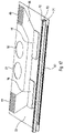
- Figure 14 shows an exploded view of a printhead 1 in accordance with the present invention, corresponding to the embodiment shown in figures 3 and 4 .
- the printhead 1 comprises four actuator modules 15, three fluid distribution modules 16, a pair of end modules 17, 18 and a common nozzle plate 19.
- the nozzle plate 19 spans several modules and has the firing nozzles formed in it; thus the nozzles can be located accurately relative to each other and the modules need only be located accurately enough that each supply of pressurised ink supply addresses a single nozzle.
- the nozzle plate comprises four rows 8 of nozzles 12, and four transducer strips 13, each for communication with a row 8 of nozzles 12.
- the printhead 1 comprises an array of individually manufactured and tested modules that are subsequently bonded to the common nozzle plate 19.
- the positioning of droplets of fluid on a printed substrate is critical and requires the positioning of the nozzles 12 to be accurate to 1-2 microns relative to the rest of the nozzles 12 in the array. This level of accuracy is achieved when all the nozzles 12 are produced on a single component.
- the actuator modules 15 are arranged with a fluid distribution module 16 between adjacent actuator modules 15. End module 17 is adjacent a first actuator module 15, and end module 18 is adjacent a last actuator module 15.
- Common nozzle plate 19 has four rows of nozzles 8 for fluid communication with the fluid distribution modules 16. When the printhead 1is assembled, the nozzle plate 19 has a width substantially equal to the transverse dimensions of the printhead, and a length in a longitudinal direction substantially equal to the longitudinal dimensions of the actuator modules 15 and fluid distribution modules 16, and, by extension, the printhead 1.
- each module of the fluid distribution module 16 and actuator module 15 there are two apertures in each module of the fluid distribution module 16 and actuator module 15.
- the apertures of the fluid distribution module 16 are aligned with the apertures of the actuator module 15, and vice versa, to form two distribution manifolds through the array.
- Figure 15 shows a printhead 1 in accordance with the present invention, corresponding to the second embodiment illustrated in figures 5 and 6 .
- the printhead 1 is shown in a partially assembled configuration immediately adjacent common nozzle plate 24.
- the assembled array 125 of printhead 1 comprises sixteen actuator modules 20, fifteen fluid distribution modules 21, two end modules 22, 23 and a single common nozzle plate 24.
- the common nozzle plate 24 has sixteen rows 8 of nozzles 12 formed in the nozzle plate 24, and sixteen transducer strips bonded thereto for communication with the rows 8.
- the modular components of the array 125 shown in exploded form to the right of the assembled array 125 in the figure provides further detail.
- the fluid distribution module 21 in exploded view immediately adjacent assembled portion of array 125 comprises a fluid distribution cavity 53 that extends through a majority of the surface area of fluid distribution module 21.
- Fluid distribution module 21 has an opening formed in a face positioned adjacent common nozzle plate 24 when the printhead 1 is assembled, the opening formed by the fluid distribution cavity 53.
- the fluid distribution cavity 53 extends toward but does not intersect with an edge of the fluid distribution module 21 opposite the face comprising the opening.
- an opening 56 extends from the edge of the fluid distribution module 21 such that a portion of opening 56 is parallel to a portion of the fluid distribution cavity 53 adjacent the edge.
- the opening 56 in fluid distribution module 21 is sized and positioned for communication with fluid distribution manifold 51 in actuator module 20 adjacent the fluid distribution module 21.
- Fluid distribution manifold 52 is substantially equal in size and position in actuator module 20 to fluid distribution manifold 51.
- Each fluid distribution manifold 51, 52 is a substantially circular through hole connecting the openings 56 in the fluid distribution modules 21 on either side of actuator module 20, and the fluid distribution cavities 56 in the fluid distribution modules 21 on either side of actuator module 20 respectively, permitting fluid flow through the printhead 1 components.
- Each actuator module 20 has a pair of electrodes 45 on a face opposite the surface of the actuator module 20 opposite that adjacent common nozzle plate 24.
- Each electrode 45 is arranged adjacent an outermost edge of the array 125 when the printhead 1 is assembled.
- the subsequent fluid distribution module 21 on the side of actuator module 20 toward end module 22 has a fluid distribution cavity 50 formed therein, and an opening 57 extending into the fluid distribution module 21 from the edge of the fluid distribution module 21 opposite the surface of the fluid distribution module 21 adjacent the common nozzle plate 24. A portion of opening 57 is parallel to a portion of the fluid distribution cavity 50 adjacent the edge.
- the subsequent actuator module 20 can be seen through the fluid distribution cavity 50.
- not all the fluid distribution modules 21 in the array 125 have an opening 56, 57 in an edge opposite that adjacent the common nozzle plate 24.
- the number and distribution of openings 56, 57 is shown in the assembled portion of array 125 as well as the exploded portion of figure 13 .
- the fluid distribution module 21 arranged closest to end module 22 has an aperture 49 in the form of a through hole that does not communicate with an edge of the fluid distribution module 21.
- Aperture 49 is arranged to communicate with manifolds 51 in adjacent actuator modules 20.
- Aperture 49 is arranged an extremity of fluid distribution cavity 50, the latter being sized and positioned for communication with fluid distribution manifolds 52 in neighbouring actuator modules 20.
- Aperture 49 is substantially equal in both size and position to adjacent manifolds 51.
- the second fluid distribution module 21 from end module 22 has an aperture 54 for communication with fluid distribution manifolds 52 in adjacent actuator modules 20.
- Aperture 54 is a through hole substantially equal in size, shape and positioning as adjacent fluid distribution manifolds 52.
- aperture 54 is formed in the planar faces of fluid distribution module 2 adjacent to, but not in communication with, an edge of fluid distribution module 21.
- actuator module 20 adjacent end module 22 is shown in a partial cut out view.
- Pumping chambers 35 are formed in the face of actuator module 20 immediately adjacent the common nozzle plate 24 in assembly.
- Metal electrodes 115 are also shown along with plating 116 that form a part of the actuation system for manipulating the piezoelectric transducer strips 13 on common nozzle plate 24.
- the fluid distribution modules 21 are shown in the present embodiment as arranged in alternating orientations.
- the fluid distribution module 21 immediately adjacent the actuator module 20 adjacent end module 22 has opening 56 connecting manifolds 51 in adjacent actuator modules 20, and fluid distribution cavity 50 cooperates with fluid distribution manifolds 52 in adjacent actuator modules 20.
- the subsequent fluid distribution module 21 in a direction toward end module 23 is in a reverse orientation, in which fluid distribution cavity 53 is adjacent and in communication with fluid distribution manifold 51, and opening 56 is adjacent fluid distribution manifold 52.
- End module 22 has a partial cavity 48 formed in planar face facing the interior of array 125 of printhead 1.
- Partial cavity 48 extends part way through the thickness of end module 22 in the manner of a blind hole, and is substantially equal in size, positioning and orientation as fluid distribution cavity 53.
- Partial cavity 48 in end module 22 is arranged for communication with the fluid distribution manifold 51 in adjacent actuator module 20.
- the portion of partial cavity 48 immediately adjacent fluid distribution manifold 51 is substantially equal in shape and size to fluid distribution manifold 51.
- heaters for adjacent nozzles are in close proximity. Pressure oscillations from boiling travels in the printing fluid from fluid delivery systems supplying adjacent nozzles, thus creating an acoustic effect that interferes with adjacent jets, and a fluidic effect wherein capillary force causes each nozzle to compete against the others to draw printing fluid into its respective flow channel, causing a shortage of printing fluid in some nozzles.
- This is known in the art as crosstalk. Crosstalk therefore causes jetting to become unstable, which causes streaking in print output.
- heat is not used to generate drops in piezoelectric printheads, piezo actuators generate waste heat during use.
- Crosstalk in thermal inkjet apparatus can be addressed by lowering the jetting frequency, but this in turn lowers the speed of the printer.
- An alternative approach is to increase the distance between heaters by narrowing the flow channel supplying adjacent heaters, or interlacing jetting start times, which staggers heating of the respective nozzles.
- the arrangement of the electrodes at the level of the individual pumping chambers, and the novel signals supplied to them mean that each pumping chamber can be fired independently of any other, whilst at the same time not applying any electric field through the printing fluid.
- an unbroken line of pixels can be produced at the boundary between adjacent printheads, even where a physical gap exists between printheads. This is known as "Printhead Stitching".
- printhead swathe boundaries are disguised by the introduction, using software manipulation, of the adjacent images of "noise” in the overlapping areas, or of tapering contributions from the two contributing swathes. Either method can be achieved by the present invention.
- Figures 16 - 30 show the construction of the actuator module according to an embodiment of the present invention.
- the present invention provides an array of transducer strips bonded to a common nozzle plate.
- the edge shooter array module (ESAM) should be electrically connected to an external power source.
- the driver integrated circuit can be internal or external to the module.
- the architecture to convey signals to the driver IC is determined for carrying signals from the driver IC to the pumping chambers.
- the driver IC will usually need to be cooled, and the trackwork protected from the printing fluid. Very high density trackwork is to be avoided, as is multi-layer trackwork, as these configurations have a higher failure rate.
- the ESAM assembly comprises a strip of piezo-electric pumping chambers 35, a pair of electrical substrates, of which at least one carries one or more driver ICs, a spacer component between the two substrates, the pair of substrate components comprising a live substrate and a passive substrate.
- the substrate components 73, 74 are insulated for conductive tracks to be mounted thereon.
- the conductive tracks connect the electronic power and signal inputs to the driver IC.
- An array of connection pads connect the tracks to the inputs of the driver IC, an array of connection pads to connect the tracks to the outputs of the driver IC.
- An array of conductive tracks connect the driver IC power and signal outputs to the transducer strip.
- the substrate components 73, 74 combine electronic function with fluidic and acoustic function by providing an array of apertures similar in size to and aligned with inlets and outlets of the pumping chambers. Fluid flow is therefore permitted through alternate chambers as some chambers are sealed. An array of apertures is shaped to form a hydraulic and acoustic continuation of pumping chambers.
- a discrete bulk PZT transducer strip 70 is attached by its sides between the two substrates 73, 74.
- the PZT strip has electrodes on one or both sides aligned with corresponding conductive tracks on the substrates 73, 74.
- the ESAM module disclosed herein is an autonomous, robust building block for a range of printhead designs. Sharing the same design and assembly processes it can be configured to fit range of drop sizes, and resolutions as it provides a common architecture for variety of inkjet printhead specifications.
- Figure 16 shows a part of the internal structure of the array 125 of printhead 1.
- An actuator module 20 according to a second embodiment is shown.
- Actuator module 20 comprises a first live substrate 73 and fluid distribution manifolds 51, 52 formed in the planar faces of the actuator module 20 as through holes.
- a pair of electrodes 45 are provided adjacent an outermost edge of the array 125 when the printhead 1 is assembled, on a face opposite the surface of the actuator module 20 opposite that adjacent pumping chambers 35.
- Electrical circuits 27 are formed on the internal surfaces 25 of the actuator module 20. The electrical circuits 27 are thus prevented from coming into contact with fluids flowing on the outer sides of the actuator modules 26.
- Figure 17 shows the internal features of the actuator module 20 of figure 16 prior to assembly of the module 20.
- the transducer strip 70 is shown as attached to the first substrate 73.
- First aperture plate 71 is assembled to the live side of the transducer strip 70, between the transducer strip 70 and first live substrate 73.
- a second aperture plate 72 is shown adjacent transducer strip 70 on a passive side of the transducer strip 70 opposite the first aperture plate 71.
- Electrical traces 90 are positioned on the first substrate 73 adjacent transducer strip 70 and aligned for bonding to the matching pattern of electrical traces on the end faces of transducer strip 70. Electrical connection can be made to external circuits by the use of electrically conductive bonds.
- Electrical traces 90 connect a pair of driver ICs 76 to electrical traces 95 that terminate in the pair of electrodes 45 positioned for external connection access when the array 125 is in assembled form.
- Figure 18 shows the connection of the electrical traces 95 on the first, live, substrate 73, and those on the first side of transducer strip 70.
- the two sets of electrodes are aligned to one another such that there is a one to one correspondence between the electrode arrays of the electrical traces 95 and the transducer strip 70.
- the alignment of the electrodes permits electrical connection between the electrical traces on the first substrate 73 and electrical traces on/in the transducer strip 70 to be formed by anisotropic conductive film (ACF) or anisotropic conductive paste (ACP) between the contacting surfaces.
- ACF anisotropic conductive film
- ACP anisotropic conductive paste
- the electrical traces 95 extend along the surface of the first, live substrate 73 toward an edge of the first substrate 73, terminating in a second array of electrodes 45.
- the pair of electrodes 45 are positioned for alignment with an array of electrodes on an external circuit board 98.
- the external circuit board 98 is a flexible circuit, comprising a driver IC and associated circuitry, and connections between the respective electrical traces are formed using ACF or ACP.
- FIG 19 shows further detail.
- the connection of the electrical traces 90 on the first, live, substrate 73 and those on the first side of the transducer strip 70 are shown aligned in an assembled form.
- the electrical traces 95 extend along the surface of the first substrate 73 from the pair of driver ICs 76 mounted on the first substrate 73 to the pair of electrodes 45.
- a further array of electrical traces 99 extends from the second array of electrodes 45.
- the electrical traces 99 are arranged for connection with further external circuitry. In a preferred embodiment, this is a flexible circuit with connections between the pairs of electrical traces made using ACF or ACP.
- Figure 20 shows the connection of the electrical traces on the second, passive, substrate 74 and those on the second passive side of the transducer strip 70.
- the actuator module 20 is formed of a first live substrate 73 and a second passive substrate 74, both substrates comprising fluid distribution manifolds 51, 52.
- the electrodes of the transducer strip 70 are aligned to the electrodes of electrical traces 94 to permit electrical connection between the electrical traces on the second substrate 74 and can be formed by ACF or ACP.
- the system of electrical traces extends along the surface of the second substrate 74 to a region toward an edge of the second substrate 74, terminating in a second array of connection electrodes.
- the second array of electrodes (not shown) are aligned with the electrodes of an external circuit board 100.
- external circuit board 100 is a flexible circuit, comprising a driver IC and associated circuitry, the connections between the pairs of electrical traces being formed using ACF or ACP.
- Figure 21 shows further detail of the connections formed with the second substrate 74.
- the connection of the electrical traces on the second passive substrate 74 and those on the second side of the transducer strip 70 are shown with the respective sets of electrodes aligned with one another to allow electrical connection by ACF or ACP.
- the system of electrical traces 97 extends along the surface of the substrate to a driver IC 102 mounted on the substrate.
- a further array of electrical traces 94 extends from the inputs of the driver IC 102 to a region near an edge of the second substrate 74, terminating at the second pair of electrodes.
- the second pair of electrodes is aligned to and obscured by an array of electrodes on external circuit board 101.
- external circuit board 101 is a flexible circuit with the connections between the pairs of electrical formed using ACF or ACP.
- Figure 22 shows a perspective view of a stiffener plate 75 for insertion between substrates 73, 74 comprising actuator module 20.
- the stiffener plate 75 has large through holes 89 substantially aligned with the fluid distribution manifolds 51, 52 in substrates 73, 74, as shown in figures 16 -21 .
- the alignment of holes 89 with fluid manifolds 51, 52 permits the passage of fluid through the substrates73, 74 and stiffener plate 75, which together form a part of the structure of the fluid manifold path.
- the stiffener plate 75 further comprises an elongate aperture 88 parallel to and spaced away from an elongate edge.
- Figure 23 shows an exploded view of the first substrate 73, the stiffener plate 75, and the second substrate 74, indicating their relative positioning.
- the first substrate 103 comprises first aperture plate 71 and first substrate 73.
- the second substrate 104 comprises second aperture plate 72 and second substrate 74.
- the stiffener plate 75 is positioned between the first substrate 103 and the second substrate 104 so that through holes 89 align with fluid distribution manifolds 51, 52 in substrates 73, 74.
- the elongate aperture 88 of stiffener plate 75 is substantially aligned with the pair of driver ICs 76 mounted on the first substrate 73 and the pair of driver ICs 102 mounted on the second substrate 74.
- the transducer strip 70 is shown assembled to the first substrate 73 in figure 23 , but when the plates 73, 74, 75 are in assembled form, the first substrate 73 is electrically connected to the first live side of transducer strip 70, and the second substrate 74 is electrically connected to a passive side of transducer strip 70.
- a bonding adhesive is applied on the contacting surfaces between the stiffener plate 75 and the substrates 73, 74 to form a hermetic seal between the components.
- the hermetic seal protects the components and connections, electrical and otherwise, within the cavities formed by the seal from ingress from the printing fluid flowing through the system.
- Figures 24 and 25 show exploded views of a transducer strip 109 and cover 107, viewed from a first side in figure 24 , and from a second side in figure 25 .
- a section of first and second aperture plates 71, 72 are shown adjacent transducer strip 109 and cover 107 sub assembly, on opposing sides of the sub assembly, such that the first side 110 of transducer strip 109 is adjacent first aperture plate 71 and the second side 111 of transducer strip 109 is adjacent second aperture plate 72.
- the first aperture plate 71 comprises apertures 82A, each with an adjacent electrode 122 formed in the surface of the first aperture adjacent the transducer strip 109.
- Each electrode 122 extends from an aperture 82A in an elongate manner.
- the apertures 82A and electrodes 122 align with channels 77A in transducer strip 109. In a preferred embodiment, the apertures 82 and electrodes 122 align with alternate channels 77A that form pumping chambers A. Electrodes 120 on first side 110 of the transducer strip join the second and third wall electrodes 115.
- the cover component 107 comprises third ports 81.
- the third ports 81 are aligned for communication with pumping chambers 77A.
- the second aperture plate 72 is shown as comprising apertures 82B and electrical circuit elements 123.
- the electrical circuit elements 123 are formed in such a manner that they extend toward apertures 82B in a linear fashion, and bifurcate to extend longitudinally adjacent opposing longitudinal sides of aperture 82B in a substantially 'y' shape.
- Each of the bifurcated portions of electrical circuit elements 123 are arranged for alignment and contact with electrodes 121A, 121B on the second side 111 of transducer strip 109. Consequently, electrical circuit elements 123 on the second aperture plate 72 aligned with electrodes 121A, 121B on the second side 111 of transducer strip 109 electrically join the first and fourth isolated wall electrodes 77B.
- Figure 26 shows a stiffener plate 75 assembled with a first substrate 103, a second substrate 104, and a transducer strip 70.
- a bonding adhesive has been applied to the contacting surfaces between the stiffener plate 75 and the first and second substrates 103, 104 to form a hermetic seal, protecting the electrical traces and components within the cavities from fluid ingress.
- Each array of modules is served by a single fluid inlet and a single fluid outlet to aid integration into the broader printhead system.
- the fluid system should be totally free of leaks as fluid should be kept completely separated from the electronic components.
- the fluid system may be however employed to cool the electronics.
- Figure 27 shows the stiffener plate 75 with the first substrate 103 in an exploded view.
- the electrical traces 45 can be seen adjacent the longitudinal edge of the stiffener plate 75.
- the array of electrical traces 45 and contact electrodes are arranged to align to the electrical traces and contact electrodes of the first substrate 103 for ACF or ACP bonding connection.
- the electrical traces 45 on the surface of the stiffener plate 75 extend from a first surface, around a longitudinal edge and on to a second surface of the stiffener plate 75 opposite the first.
- the electrical traces 45 form a pad 105 that can be connected to further arrays forming pads on external circuits, providing a connection for an external source of power and control signals to power the circuits and driver ICs on the edge shooter array module.
- Figure 28 shows the arrangement of figure 27 fully assembled, the first substrate 103 bonded to the stiffener plate 75 by ACF or ACP.
- Figure 29 is an exploded view showing how performance information can be obtained from the edge shooter array actuator module 20, if desired.
- Actuator module 20 is attached to a temporary nozzle plate 47 and a pair of temporary fluid distribution modules 46 in place of permanent fluid distribution modules.
- Test signals can be applied to the actuator module 20, via electrodes 45 on the longitudinal edge of the module, to activate the internal circuitry of the actuator module 20.
- the materials on to which the circuits are formed should be insulating in order to avoid short-circuits. Suitable materials include glass, ceramic, PZT and LCP.
- Figures 30 - 47 show the transducer strips along the lower edge of the actuator module of figures 16 onwards.
- the present invention provides a printhead based on a compact array of discrete bulk ceramic transducer strips attached to a common nozzle plate.
- the layout comprises an array of transducer strips bonded to a common nozzle plate in which the ink supply is physically compact to allow high overall nozzle density based on the use of piezoelectric ceramic material operating in shear-mode.
- the transducer strips are positioned, located and bonded to a nozzle plate, as opposed to a common substrate.
- this solution provides increased performance over bonding transducers to a substrate, or forming them on a substrate, making the electrical connections and subsequently applying a nozzle plate.
- the dimensions of the pumping chambers are well-matched to the required drop volume for the application.
- the geometry of the transducer strips is a right rectangular prism so bonding and sealing are simplified. Furthermore, the geometry gives the most efficient acoustic termination at the ends of the pumping chambers.
- the cover wafer is produced with rows of apertures arranged to align with the centres of the pumping chambers in the diced strips.
- Each strip comprises an array of pumping channels, each with an aperture in the cover wafer aligned to the centre of the pumping chamber.
- Electrodes are formed on the faces of the strips formed by the dicing process overlaying and connecting to the electrodes in the pumping chambers and isolated channels. Electrodes may be formed on one or both of the faces at each end of the pumping chambers.
- the electrodes are formed by known processes, such as vacuum deposition process.
- the patterning of the electrodes can be formed by a known contact mask process.
- the patterning of the electrodes is formed by a laser direct-writing process.
- the strips can be electronically tested by taking continuity and resonance behaviour data of the transducer walls to assess the electrical and mechanical integrity of the strip. This can be completed prior to bonding to the common nozzle plate to improve production yields.
- the transducer strips are bonded to a common nozzle plate in such a manner that the centres of the holes in the cover wafer are aligned to the axes of the nozzles in the nozzle plate.
- the strips are preferably bonded to the common nozzle plate using a UV curing adhesive.
- the system of the present invention provides a scalable common approach for larger numbers of transducer strips. For example, 20 strips may be accommodated.
- Each array of modules is served by a single fluid inlet and a single fluid outlet to aid integration into the broader inkjet system.
- the fluid system must be totally free of leaks. Fluid must be kept completely separated from the electronic components.
- the fluid system may be used to cool the electronics systems and components.
- Each array of compact fluid distribution modules is interleaved with an array of actuator modules. This enables high nozzle density in the printhead from a low nozzle density in each actuator module. End fluid distribution modules terminate the array at opposing ends.
- the fluid distribution and actuator modules are bonded together to form a solid and sealed unit.
- each module of the fluid distribution module and actuator module there are two apertures in each module of the fluid distribution module and actuator module.
- the apertures of the fluid distribution module are aligned with the apertures of the actuator module, and vice versa, to form two distribution manifolds through the array.
- the same fluid distribution module is used for routing the fluid both to and from the pumping chambers by providing fluid distribution modules in opposing arrangements alternately. Alternate fluid distribution modules are effectively rotated 180 degrees along a longitudinal axis.
- This arrangement provides a manufacturing advantage in that the same component used throughout the printhead, and a performance advantage in that an equal pressure drop is maintained both upstream and downstream of the pumping chambers. Consequently, the fluid pressure at a nozzle is the average of the pressures between the input and the output, and is independent of fluid volume flow rate.
- Distribution cavities in fluid distribution modules form channels for fluid flow in or out of a transducer strip pumping chamber to an array of fluid connection ports on accessible areas of the array, either directly or through the distribution manifolds.
- the fluid flow is arranged throughout the array of fluid distribution modules and actuator module to remove the heat generated by the embedded electronics components.
- the positioning of the active electronics and shape of the cavities ensure that all fluid passes close to the surface supporting the ICs.
- Figure 30 shows a piezoelectric ceramic wafer 106 after forming by channel sawing, plating etc.
- the pumping chambers are formed of a wafer of piezoelectric material divided by a dicing saw.
- Pumping chambers are formed in alternate sawn channels, divided by dry channels formed therebetween. Electrodes may be formed on one or both of the faces at each end of the pumping chambers.
- the wafer 106 shown is at an intermediate point in its fabrication.
- the formed wafer 1063 can be divided into individual transducer strips 70.
- the piezoelectric ceramic material is preferably plumbium zirconium titanate (PZT).
- PZT plumbium zirconium titanate
- the manufacturing process utilises as much of the PZT wafer 106 as possible in the product, thus creating a cost efficiency as well as a higher quality product.
- each pumping chamber 35 can be electrically tested prior to the next stage of manufacture to reduce scrap and wastage.
- the PZT ceramic wafer 106 is sandwiched and bonded between two thin layers of glass, a cover wafer 107 and a base wafer.
- the thermal coefficient of expansion of the glass wafers is closely matched to the thermal coefficient of expansion of the PZT.
- the bonds are made using a UV-curing adhesive.
- the laminated wafer assembly can be cut into transducer strips 109 using a dicing saw, producing the arrangement shown in figure 31 .
- the bonded assembly has channels 77, 78 formed in a planar surface along an edge transverse the longitudinal axis of the assembled wafer 106, 107.
- the channels 77, 78 extend a short distance in a longitudinal direction relative the length of the wafer.
- Each of the channels 77, 78 have a substantially equal width and are spaced equally with walls 83 therebetween.
- the channels are formed in two depths; a shallower pumping chamber channel 77 is formed alternately with a deeper dry channel 78.
- the depth of the deeper dry channels 78 extends to a depth of less than half of that of the wafer.
- Transducer strip 109 comprises channels 77, 78 formed in the wafer 106, with walls 83 therebetween.
- the channels are formed in two depths; a shallower pumping chamber channel 77 is formed alternately with a deeper dry channel 78.
- the depth of the deeper channels extends to a depth of less than half of that of the wafer 106.
- the channel surfaces formed in the wafer 106 have been covered with metal electrodes 115, 116.
- the shallow channels are pumping chamber channels 77, and as such are "wet" in that they carry printing fluid.
- Plating 115 has been applied to the wall surface in the shallow pumping chamber channels 77.
- Plating 116 has been applied to the surfaces of the faces of the opposing walls in the two dry channels 78.
- All fluid channels 77 have the same fluid inlet pressure and, for improved through flow, have the same fluid outlet pressure.
- the equilibrium of pressure through the pumping chamber channels 77 is constant through time.
- the temperature of fluid supplied to each channel 77 is substantially equal and also constant overtime.
- FIG 32 is a section detail of a single, autonomous pumping chamber 77 sub-module of a transducer strip 109.
- the sub-module comprises a common pumping chamber channel 77 between walls 83 with dry channels 78 to either side.
- the transducer strip 109 is shown at an intermediate point in the fabrication process.
- Plating 115 covers the surface of the shallow pumping chamber channel 77, and plating 116 covers the surfaces of the adjacent dry channels 78.
- the plating 115, 116 covers the upper and lower sections of wall 83.
- Figure 33 shows the section detail of the transducer strip 109 formed from the wafer 106 of figure 30 at a subsequent stage in the fabrication process to that shown in figure 32 .
- Isolation cuts 117 have been formed at the base of dry channels 78.
- the isolation cuts 117 remove a portion of plating 116 at the bases of the deeper, dry channels 78, dividing the plating 116 into two separate pieces 116A, 116B.
- Figure 34 shows a section detail of the transducer strip 109 of figure 33 .
- the isolation cuts 117 provide additional depth to dry channels 78 and breaks the electrical connection between adjacent pumping chambers 77.
- the finished transducer strip 109 is substantially straight and dimensionally stable.
- the positions of the pumping chambers are substantially aligned to the nozzles on the common nozzle plate.
- the resulting structure when assembled with aperture plates 71, 72 and cover 107 as shown in figures 35 - 47 , as well as suitable patterns of electrical interconnections, comprises a functionally autonomous pumping module.
- Application of differential voltage between the electrodes across the walls cause the PZT to deflect in a shear mode and for the walls to move laterally. This in turn causes the cross-sectional area of the chambers to change, and for pressure to change in fluids contained in the chambers.
- the pumping chamber 77 electrode pairs 116A, 116B are supplied with a common actuation signal. Fire or no-fire signals are supplied to the isolated channel electrodes on either side of each of the pumping chambers.
- the pumping chamber 77 electrode connections and waveforms are arranged to produce a zero or substantially zero electric field through the fluid to allow jetting of electrically conductive fluids.
- Figure 35 shows an assembly in which a completed wafer 106 has been bonded with cover wafer 107 to form a completed transducer strip 70.
- the cover wafer 107 is fabricated from borosilicate glass.
- the cover wafer 107 has third ports 81 formed therein by a selective laser etching process.
- the third ports 81 are aligned for communication with the shallow pumping chamber channels 77.
- the cover wafer 107 is formed of a transparent glass, alignment with the underlying components is quicker and easier, and may be achieved visually, either manually or automatedly.
- the cover wafer 107 is affixed to wafer 106 by application of UV curing adhesive, in place of traditionally used thermal epoxies, allowing for optical examination of bond quality, an accelerated process, and to minimise thermal expansion.
- Figure 36 shows a section detail of section of completed transducer strip 70.
- the walls 83, pumping chamber channels 77, and dry isolated channels 78 of the transducer strip 70 are shown with the thin films of electrically conductive electrical traces 84 on the surfaces of walls 83 forming the sides of pumping chamber channels 77.
- Indicative conductive electrical traces 85, 86 are shown on the transverse end face of the transducer strip 109.
- the cover 107 is attached to the transducer strip 109 at the extremity of walls 83 such that third ports 81 are in communication with shallow pumping chamber channels 77 and the nozzles in the nozzle plate (not shown).
- Electrical traces 85 extend along the surface of a transverse face of the transducer strip 70, in a direction away from the pumping chamber channels 77. Electrical traces 85 extend in an elongate strip away from the pumping chamber channels 77 by a distance that is greater than the depth of the associated pumping chamber channel 77.
- Electrical traces 86 extend along the surface of a transverse face of the transducer strip 70 for electrical connection between the transducer strip 70, plating 116A in a first dry channel 78, and plating 116B in a second dry channel on an opposing side of a pumping chamber channel 77. Electrical traces extend around electrical traces 85 in a u-shape arrangement.
- FIG 37 shows a transducer strip 109 assembled with cover 107.
- Further electrodes 120, 121 have been formed on the transverse face of transducer strip 109 for electrical connection between the end face of transducer strip 109 and the electrodes on the dry chamber walls 116A, 116B.
- Further electrode 121 covers electrode traces 86 on transducer strip 109, and further electrode 120 covers electrical traces 85.
- Further electrode 121 extends linearly from a location adjacent plating 116A of dry chamber 78 such that a side of the further electrode 121 is coplanar with a portion of plating 116A.
- As the further electrode 121 is linear in extent toward the face of the transducer strip 109 opposite that adjacent cover 107, further electrode 121 is offset from isolation cut 117.
- As further electrode 121 covers electrode traces 86 on transducer strip 109, it is provided in a substantially u-shaped arrangement.
- the further electrode 120 is only formed adjacent the third of the five pumping chamber channels 77 of the embodiment. Likewise, only one further electrode 121 extends around and is offset from further electrode 120 in a u-shaped arrangement such that the plating 116A of the third of the dry chambers 78 is electrically connected to the plating 116B of the fourth of the six dry chambers 78.
- the further electrodes can also be formed in a number of alternative arrangements, including, but not limited to, those detailed below.
- Figure 38 shows further electrodes 120, 121 on a first transverse face of the transducer strip 109.
- Further electrode 120 extends from the base of pumping chamber channel 77 in a direction away from the cover 107.
- Further electrode 120 has substantially the same width as pumping chamber channel 77 and extends for a length at least that of the depth of pumping chamber channel 77, and is substantially the same as that shown in figure 37 .
- Further electrode 121A is arranged in elongate form extending away from dry channel 78 in a direction away from the cover 107.
- Further electrode 121A electrically connects the transducer strip 109 to the dry chamber wall plating 116B.
- the further electrode 121A extends linearly adjacent plating 116B from a first end.
- the further electrode 121A extends from the first end beyond isolation cut 117 such that it is offset from isolation cut 117.
- the further electrode 121A then broadens so that a portion extends linearly away from and substantially coplanar with plating 116A of the same dry channel 78 as that comprising the plating 116B with which it is coplanar to an extent at the first end.
- the first end of further electrode 121A terminates at a position substantially coplanar with the first end of further electrode 120.
- Further electrode 121A extends to a second end opposite the first that terminates at a position offset from the extremity of the transverse surface of the transducer strip 109.
- Further electrode 120 extends to a second end opposite the first that terminates at a position offset from the extremity of the transverse surface of the transducer strip 109 that is substantially coplanar with the second end of further electrode 121A.
- a further electrode 120 extends adjacent each of the five pumping chamber channels 77. However, only five of the six dry channels 78 are electrically connected to further electrodes 121A.
- Figure 39 shows further electrodes 121B on a second transverse face of the transducer strip 109 opposite the first transverse face, in accordance with a first embodiment of the transducer strip 109 of the present invention. Further electrodes 121B are shown in a u-shaped arrangement electrically connecting a first dry chamber channel 78 wall plating 116A to wall plating 116B of a subsequent second dry chamber channel 78. Further electrode 121B is offset from and extends past the base of pumping chamber 77 located between the first dry chamber channel 78 and the second dry chamber 78 in transducer strip 109.
- Figure 40 shows the further electrodes 120, 121 on the first transverse face of the transducer strip 109 in a second embodiment of the transducer strip 109 of the present invention.
- This embodiment shows further electrodes extending adjacent each of the five pumping chamber channels 77 in a manner similar to that shown in figure 37 ; the further electrode 121 is substantially as shown in figure 37 . Consequently, five further electrodes 120 and five further electrodes 121 connecting the plating 116A, 116B or adjacent dry chambers are present.
- Figure 41 shows the second transverse face of the transducer strip 109 in the second embodiment of the transducer strip 109 of the present invention.
- Figure 42 shows the further electrodes 120, 121A on the first sides of the transducer strip 109 in a third embodiment of the transducer strip 109.
- the further electrodes 120, 121A are substantially as described in relation to figure 38 .
- Further electrodes 121B are present adjacent cover 107.
- Electrodes 121B are substantially as described in relation to figure 39 but in an opposite arrangement. Electrodes 121B are positioned at opposite ends of pumping chamber channels 77 from further electrodes 120 so that a portion of electrode 121B overlies a transverse face of cover 107.
- Electrode 121B electrically connects plating 115 of pumping chamber channel 77 with plating 116A of dry chamber channel 78 to a first side of pumping chamber channel 77 and plating 116B of dry chamber channel 78 to a second side of pumping chamber channel 77.
- Figure 43 shows the second side of the transducer strip 109 in a third embodiment of the transducer strip 109 of the present invention.
- Figure 44 shows the further electrodes 120, 121A, 121B on the first sides of the transducer strip 109 in a fourth embodiment of the transducer strip 109.
- Further electrodes 120, 121A, 121B are substantially as described herein above with reference to previous figures.
- Each pumping chamber channel 77 has a further electrode 120 extending therefrom on a transverse face of transducer strip 109.
- Further electrodes 121A, 121B are arranged such that each further electrode 120 has further electrode 121A adjacent one side, and further electrode 121B adjacent another side in a symmetrical arrangement.
- Further electrodes 121A, 121B are elongate and symmetrical in shape.
- Further electrode 120 extends across the transverse face of transducer strip 109 by a distance smaller than the extent of further electrodes 121A, 121B.
- Further electrodes 121A, 121B are of substantially equal extent.
- Figure 45 shows the electrodes 120, 121 on the second side of the transducer strip 109 in a fourth embodiment of the transducer strip 109 of the present invention.
- FIG 46 shows the further electrodes 120, 121A on the first sides of the transducer strip 109 in a fifth embodiment of the transducer strip 109.
- Further electrodes 120, 121A are substantially as described herein above with reference to previous figures.
- Each pumping chamber channel 77 has a further electrode 120 extending therefrom on a transverse face of transducer strip 109.
- Five of the six dry chamber channels 78 have further electrodes 121A extending therefrom on a transverse face of transducer strip 109.
- Both the further electrodes 120, 121A have substantially the same extent, which terminates short of the edge of transverse face of transducer strip 109.
- FIG 47 shows the electrodes 121B on the second side of the transducer strip 109 in a fifth embodiment of the transducer strip 109 of the present invention. Electrodes 121B are substantially as described in relation to figure 42 in form, orientation, and location.
- Figure 48 shows an exploded view of a portion of an array 125 of printhead 1 with three actuator modules 20 and four fluid distribution modules 21.
- the portion of the array 125 is shown in partially sectioned form. Arrows are provided to indicate the direction of fluid circulation within the array 125.
- the partial printhead assembly comprises an array 125 of modules, alternating between actuator modules 20 and fluid distribution modules 21.
- the fluid pumping chambers 35 are arranged near a second longitudinal edge 33 of the actuator modules 20. Fluid is supplied to one side of the pumping chamber 35 via a cavity 50, 53 in a first adjacent fluid distribution module 21, and returned via the cavity 53, 50 in a second adjacent fluid distribution module 21.
- the modules 20, 21 are assembled and bonded using a curable resin that forms a fluid tight seal between the bonded surfaces.
- Both the actuator modules 20 fluid distribution modules 21 are parallel-sided, narrow-section plates. This geometry allows a large number of pumping chambers and nozzles to be fitted into a small cross-sectional area.
- each fluid distribution module 21 serves the two actuator modules 20, one on either side, allowing the modules 20, 21 to be arranged closely together.
- alternate actuator modules 20 are oriented in opposite configurations. This ensures that a first side 30 of an actuator module 20 faces a first side 30 of the closest actuator module 20. A second side 31 of a first actuator module 20 faces a second side 31 of a subsequent actuator module 20.
- a cavity in a fluid distribution module can therefore provide a feed path to two closest or adjacent actuator modules 20, or as a return path to two adjacent actuator modules 20. Consequently, the fluid always flows from the second side 31 of any actuator module in the array to the first side 30.
- the arrangement of alternative configurations ensures an equal pressure drop both upstream and downstream of the chambers so that the fluid pressure at the nozzle is the average of pressures between input and output independently of the volume flow rate.
- Figure 49 shows an exploded view of an actuator module 20 together with a fluid distribution module 21 and an end module 22.
- the end module 22 provides a fluid flow path to one side of the adjacent actuator module 20, and a termination to the common fluid manifold linking the actuator modules 20 via the fluid distribution manifolds 51, 52.
- the fluid path in the end module 22 is essentially the same as that of the fluid distribution module 21. This ensures that the fluid flow and pressure in the first and last actuator modules 22, 23 is the same, or substantially the same, as those in the rest of the actuator modules 20 in the array.
- end module 22 has a blind hole fluid distribution manifold 43 for directing the fluid in the fluid flow path back toward adjacent actuator module 20.
- the end fluid distribution plate 22 has a blind cavity 50 linked to and aligned with manifold 51.
- the portion of the blind cavity 50 aligned with manifold 51 is of substantially equal size and shape to manifold 51.
- blind cavity 53 is linked to and aligned with manifold 52.
- the portion of the blind cavity 53 aligned with manifold 52 is of substantially equal size and shape to manifold 52.
- Manifolds 51, 52 are substantially equal in size and shape, as are blind cavities 50, 53. Consequently, similar fluid flow characteristics are provided to the outer ends of the first and last actuator modules as those in the middle of the array served by the fluid distribution modules 21.
- Figure 50 shows an arrangement in which the orientations of alternate actuator modules 20 are reversed.
- Each fluid distribution module 21 is provided with two through-hole apertures 51, 52 aligned with the through-holes apertures 51, 52 in the actuator modules 20 to form elongate manifolds when the modules are assembled and bonded into a stack.
- Aperture 52 in fluid distribution module 21 is a section of fluid distribution cavity 53 that corresponds with apertures 52 of adjacent actuator modules 20, and aperture 51 is a section of fluid distribution cavity 50 that corresponds with apertures 51 of adjacent actuator modules 20.
- Each aperture 51 has substantially the same size and geometry and is aligned such that the internal faces of each of the apertures 51 are coplanar.
- Each aperture 52 has substantially the same size and geometry and is aligned such that the internal faces of each of the apertures 52 are coplanar.
- one of the two through-hole apertures 51 are connected to the exterior of the stack at the elongate edge of the module by means of openings 56. These apertures 51 are fluidically connected to fluid distribution cavities 50 in the assembled device.
- the second through-hole aperture 52 in actuator module 20 of is connected to the exterior of the stack by opening 57 in a fluid distribution module 21.
- the aperture 52 is fluidically connected to fluid distribution cavity 53 in the assembled device.
- the widths of all the actuator modules 20 and all the fluid distribution modules 21 are equal.
- the lengths of the modules 20, 21 are equal and the front and rear faces of all the modules are co-planar, to enable fluid-tight seals to be formed between the faces on assembly, with a nozzle plate 24 at a second end adjacent second longitudinal edge 33 of actuator module 20 and a fluid interface plate 34 at a first end opposite the second.
- Figure 51 shows the geometry of the inlet side of the fluid path, in which the cavities are shown as solid bodies.
- Fluid distribution cavity 53 in fluid distribution module 21 comprises through hole manifold 52, which connects to the exterior of the fluid distribution module 21 via opening 57 in first end module 60 forming a fluid distribution module.
- the fluid distribution cavity 53 and pumping chambers 35 form a fluidic circuit, causing fluid to flow from the high-pressure input manifold to the input ends of the pumping chambers 35 and back to the low-pressure output manifold. Fluid is supplied to one side of the pumping chamber 35 via a cavity 53 in the fluid distribution module 21.
- Fluid distribution cavity 50 in fluid distribution module 21 comprises through hole manifold 51, which connects to the exterior of the fluid distribution module 21 via opening 56 in first end module 60 forming a fluid distribution module.
- the fluid distribution cavity 50 and pumping chambers 35 form a fluidic circuit in which fluid is supplied to fluid distribution cavity 50 via one side of the pumping chamber 35 in fluid communication with fluid distribution module 21.
- Figure 53 shows the detail of figures 51 and 52 in an assembled actuator module 15.
- the geometries of manifolds 51, 52 and the cavities 53, 50 in the fluid distribution modules 21, are the same on both the inlet side and the outlet side. Any pressure drop due to viscous flow is therefore equal, or substantially equal, on each side for all flow rates, provided the viscosity on both sides remains the same, or substantially the same.
- connections between the first and second elongate manifolds 51, 52 are externally connected via openings 56, 57 in the actuator module 15.
- figure 54 shows a section of blind cavities 51 in the end fluid distribution modules 22 are replaced by through-holes 62, 63 in end fluid distribution plates 17, 18. This arrangement allows fluid to flow into and out of the end fluid modules 17, 18 instead of the openings toward the elongate edges.
- the connections between the first and second manifolds 51, 52 and the external environment are provided by openings 56, 57 in actuator module 15, and in apertures 62, 63 in the end fluid distribution plates 17, 18.
- FIGS. 50 and 54 show the fluid distribution modules in alternate reversed orientations.
- a web 61 divides cavity 51 on a first side from cavity 53 on a second side. Both cavities are fluidically joined to the same through-hole aperture.
- Figure 55 shows a further embodiment in which a portion of an array 125 is shown in exploded and partially sectioned form.
- the array 125 portion has three actuator modules 20 and three fluid distribution modules 55.
- the orientations of the actuator modules 20 and fluid distribution modules 55 are different from those shown in figures 49 and 54 .
- the actuator modules 20 are all oriented in the same manner with apertures 56 lying in a same longitudinal plane and are in fluid communication with fluid distribution manifolds 51.
- all apertures 57 also lie in the same longitudinal plane and are in fluid communication with fluid distribution manifolds 52.
- the common fluid inlet manifolds 56 are in fluid communication with the inlet cavities 59 in the fluid distribution modules 55.
- the common fluid outlet manifolds 57 are in fluid communication with the outlet cavities 58 in the fluid distribution modules 55.
- Figure 56 shows the direction of fluid flow in the embodiment of figure 55 .
- Fluid is introduced through opening 56 in fluid distribution module 55.
- the fluid flows through cavity 59, past the second side 31 of actuator module 20, and through the pumping chambers 35, and via second cavity 58.
- the fluid passes under the driver IC to provide cooling, and exits (ultimately) at second cavity 58 in first end module 60.
- This arrangement ensures that the fluid remains at a controlled temperature when it passes through the pumping chambers 35.
- the fluid is sourced directly from the fluid supply system and will not have been heated by the driver IC. This is beneficial in ensuring that the viscosity and other fluid properties remain constant during use, and allows heat generated from electrical energy to mechanical pressure energy transduction process to be dissipated quickly and efficiently. This aids in maintaining uniformity of jetting performance and of maximising reliability of jetting.
- end module 60 has a blind hole fluid distribution manifold 44 for directing the fluid in the fluid flow path back toward adjacent actuator module 20 and fluid distribution manifold 52.
- Figure 57 shows the geometry of the inlet side cavity 58 of the fluid path
- figure 58 shows the geometry of the outlet side cavity 59 of the fluid path of the embodiment shown in figures 55 and 56 , along with pumping chambers 35, in which the cavities are shown as solid bodies.
- Figure 59 shows a combination of the geometry of the inlet side of the fluid path 58, and the geometry of the outlet side of the fluid path 59 of figures 57 and 58 .
- the arrangements of figures 57 - 59 function substantially as those shown in figures 51 - 53 .
- the geometries of the inlet and outlet fluid manifolds, formed by cavities 58 and 59 in the fluid distribution modules 21, are substantially geometrically the same on both the inlet side and the outlet side. Any pressure drop due to viscous flow is therefore equal, or substantially equal, on each side for all flow rates, provided that the viscosity on both sides remains the same, or substantially the same.
- the fluid flow through the pumping chambers 35 and past the first side of the actuator module 20, provides cooling to the electrical circuitry and driver ICs mounted on the first side of the actuator module.
- the inlet sides of adjacent actuator modules face one another on either side of a shared fluid distribution manifold.
- the outlet sides of the adjacent pair of actuator modules face one another on either side of a shared fluid distribution manifold. Consequently, a single fluid distribution module can supply the inlets of two actuator modules, and a single fluid distribution module can supply the outlets of two actuator modules.
- each of the modules 18, 20, 21, 55, 60 are equal, and the front and rear planar faces of the modules are co-planar to enable fluid-tight seals to be formed between adjacent faces, and placement of a common nozzle plate at one end and a fluid interface plate at another end opposite the first.
- the arrangement of the present invention comprises large numbers of pumping chambers and print modules in a small volume; this arrangement can result in a further source of crosstalk.
- the secondary crosstalk can originate from interference between neighbouring transducer strips 13, 70 on either side of a given fluid distribution module 16, 21.
- any acoustic energy affecting a neighbouring pumping chamber 35 will interfere with the acoustic wave intentionally produced in said chamber by piezoelectric actuation. If the interference is additive, the energy coupled into the droplet will be greater than intended, resulting in a faster, larger drop than intended. If the interference is subtractive, the drop will be slower and smaller than required.
- quarter-wave anti-reflective coatings In neighbouring technologies, such as optical instruments, in which unwanted wave-born energy is also preferably eliminated, it is possible to use quarter-wave anti-reflective coatings. However, these only work at specific frequencies or wavelengths. Acoustic waves are formed of a spectrum of different frequencies. Consequently, absorption methods based on quarter-wave structures are not likely to be effective in the present arrangement.
- the acoustic absorber of the present application comprises a closed tube with thin, flexible walls.
- the acoustic absorber is preferably fabricated of a polymeric material, and positioned close to both the ends of two neighbouring transducer strips, and to the nozzle plate.
- the cross-section of the tube is preferably wedge-shaped to reflect acoustic waves hitting the surface are both into the manifold and/or refracted into the material.
- the acoustic wave pressure causes deflection of the tube surface, providing a second energy absorbing mechanism.
- the acoustic absorber reduces the amplitude of the acoustic waves at source, e.g. as they emerge from the ends of the pumping chambers, by the addition of acoustic baffles. This reduces the efficiency of the coupling as the unwanted waves enter neighbouring chambers.
- the sound waves are refracted into an energy absorbing structure near the ends of the pumping chambers, and the sound waves are reflected to a distant part of the system where they can safely dissipate without impacting on system performance.
- the coherence of the acoustic waves is reduced by forcing them to take a variety of different pathways of different lengths between neighbouring and opposing chambers
- Acoustic energy can be quickly turned into thermal energy by using the acoustics to expand and contract materials and structures. We therefore prefer elastomeric or polymeric materials that have a high stress vs. strain hysteresis loss.
- Crosstalk is most acute when systematic errors occur in the printed image. Random errors in pixel positions are less of a problem, certainly in graphic images, although some functional fluid-based applications, such as flat screen display printing are sensitive.
- Figure 60 shows an acoustic damping component 36 bonded to the side of each actuator module 20, 26 in front of pumping chamber apertures (not shown) in a partially constructed array 125.
- Each of the fluid distribution modules 20 have fluid distribution manifold apertures 51, 52 that are aligned in a longitudinal direction.
- the partial array 125 of figure 60 has three actuator modules 20 interleaved with fluid distribution modules 21.
- the first of the fluid distribution modules 21 has a fluid inlet manifold 56 for receiving printing fluid.
- the second of the fluid distribution modules 21 has a fluid outlet manifold 57 for passage of fluid to the exterior of the assembled array.
- Figure 61 shows a section view of the rear portion of the modular array of figure 60 showing the positioning of the acoustic damper in the assembled array.
- the array of modules 20, 21 is sectioned along a plane in the longitudinal direction relative the array 125 taken along a geometric centre line between fluid distribution manifold apertures 51, 52.
- Pumping chambers 35 can be seen adjacent actuator module 20 for fluid communication between fluid distribution modules 21. Fluid distribution cavity 50 is visible in fluid distribution module 21. A first acoustic damping component 36 can be seen adjacent pumping chamber 35 between the fluid distribution modules 21 to either side of actuator module 20. A further acoustic damping component 36 can be seen adjacent the rear fluid distribution module 21.
- the internal surface of the acoustic damping component 36 is profiled to deflect the ultrasonic waves emerging from the pumping chambers 35 away from neighbouring chambers, and to prevent the ultrasonic waves from re-entering the originating pumping chamber 35.
- the two-wall separation also prevents acoustic interference between neighbouring actuator modules 20.
- Figure 62 shows the location and surface profiles of the acoustic dampers in a section view of the arrangement of figure 60 .
- the array of figure 60 is sectioned along a plane in the longitudinal direction relative the array 125 taken along a geometric centre line between fluid distribution manifold apertures 51, 52.
- the internal surface of the acoustic damping component 36 is profiled to deflect the ultrasonic waves emerging from the pumping chambers 35 away from neighbouring chambers, and to prevent the ultrasonic waves from re-entering the originating pumping chamber 35.
- the two-wall separation between neighbouring actuator modules 20 can be clearly seen extending into fluid distribution cavities 50, 53.
- the Modular Edge Shooter Array system is characterised by shear-mode actuated pairs of PZT walls either side of pumping chambers.
- the active pumping chambers are arranged in an alternate line configuration.
- Each of the air-filled chambers has isolation cuts 117 to form fully independent channels.
- the MESA system is driven by unipolar driver chips, by 3-level driver or Bi-polar driver chips, or by arbitrary waveform driver chips. Actuation is in a 1-cycle, 1-phase; 1-cycle, 2-phase; 1-cycle, 3-phase; 1-cycle, 4-phase; or 1-cycle, 6-phase firing arrangement.
- the system of the present invention comprises inkjet actuators operating in the acoustic fill then fire mode.
- the pumping chamber is expended to admit fresh ink, the chamber is squeezed, and then relaxed to a neutral state.
- the pumping chamber walls can be moved in both directions from the neutral position, the pumping chambers having relatively open inlets for acoustic firing.
- Acoustic lengths are measured in units of time and represent the time taken for an acoustic wave to travel from the open end of the pumping chamber, along the chamber, and back to the open end again. In the case of a through-flow channel as used in our device, this means the time it takes for an acoustic wave to travel from the open end of the channel, past the nozzle and to exit the channel at the far end.
- the time taken for an acoustic wavelength is a function of the length of the channel and the speed of the acoustic wave in the channel. Consequently, larger drop sizes require larger and longer channels. Different fluids have different speeds of sound. It is therefore a system requirement that the timing of the electrical pulses that generate acoustic pulses is changeable.
- a negative pressure is induced for one acoustic length, followed by a positive pressure for two acoustic lengths.
- a positive pressure for two acoustic lengths.
- a settling period for binary waveforms, this is followed by a settling period of three acoustic lengths, as shown in figure 63 .
- the waveform pictured produces two initial drops, each consisting of four sub-drops, followed by a third drop consisting of three sub-drops, and finally a drop consisting of two sub-drops.
- bursts of sub-drops with fewer than the maximum number start their bursts later than the four drops per drop nozzles. These are termed right-justified waveforms. Systems that start their bursts at the same time but finish at different times are termed left-justified waveforms. We prefer right-justified waveforms.
- impulses are shorter in duration than those of binary waveforms.
- Binary waveforms are longer because the drop size is larger than the individual droplets that make up a greyscale burst.
- the binary pumping chambers are consequently larger and longer than the greyscale chambers, having longer acoustic lengths and lower firing frequencies.
- Desirable criteria for a waveform include:
- the first of these is a function of the acoustic length, which is dependent on chamber dimensions, which in turn is dependent on drop volume. Acoustic length is also somewhat dependent on fluid type (as the speed of sound in different fluids will vary), so the duration is essentially fixed for a given application.
- the duration is three acoustic lengths (including the settling period between drops) plus three acoustic lengths times the number of greyscale levels.
- the second factor is dominated by the dwell time between firing pulses, largely dictated by the time spent waiting for other cycles to finish their work.
- a 3-cycle system (which might be imposed by the use of a shared-wall, all-channels firing approach) will typically operate at one third of the frequency of 1-cycle systems.
- 1-cycle systems are enabled by alternate channels being air-filled, such as in the present embodiment. This, in turn, is enabled by the ability to reliably close off the air-filled channels from the fluid manifold and prevent ingress of the fluid into those channels.
- Electric fields can damage inkjet inks by upsetting the delicate balances of electrostatic forces that keep pigment or other particles in suspension in the carrier fluid. This is true for conductive and non-conductive fluids.
- Conductive fluids which really means aqueous fluids, present additional challenges to the inkjet system. If the system allows electric fields to be generated in the fluid, and for that field to produce a current through the fluid, then electrolysis will occur. This has two important consequences. Firstly, bubbles of hydrogen and oxygen will be generated at the electrodes. Secondly, the electrodes will start to be dissolved in the water. Bubbles in the fluid will quickly interfere in the jetting process because the pressure pulses that should be ejecting droplets will instead begin to expand and contract the bubbles. Also, the electrodes may become damaged due to electrolytic attack.
- Jetting reliability refers to the ability of the system as a whole to maximise the mean time between failures. For systems with high numbers of nozzles, this is obviously more challenging than for systems with fewer nozzles.
- the reliability of individual nozzles is mostly a function of how well the waveform is designed for the particular combination of fluid and actuator.
- the pressure in the ink manifold is something else that the present invention seeks to optimise.
- the pressure in the manifold generally will vary according to what proportion of the nozzles are firing at a given moment. It will also vary locally, for individual pumping chambers, as a result of what its near neighbours are doing. Some waveforms emit high levels of acoustic energy, others less so. Acoustic waves emanating from the end of one channel propagate through the manifold and feed into the open ends of near neighbours. If the wave happens to be in phase with the operation of the second channel, then the result will be a larger and faster droplet in the second channel. If it is out of phase, then a smaller, slower droplet will result.
- Waveforms can be contrived to add together with those from neighbouring channels in such a way that the average is zero, or close to zero, depending on the actual pattern of drops being printed. It is therefore an aim to use this at least to minimise the pressure fluctuations in the manifolds.
- the voltage applied to the walls when applying positive pressure is half that applied when the negative pressure is being applied. This is because in the acoustic firing scheme, the negative pressure (Fill) stage is half the duration of the positive pressure (Fire) stage.
- a ratio of 1:2 in voltage, and hence wall movement compensates for the 2:1 ratio in the times spent in the two stages. If the ratio of Fill time to Fire time were 1:3, then the voltage ratio would ideally be 3:1. However, not all channels fire all the time and this makes perfect pressure cancellation very difficult.
- the drops emerge from the nozzle plate at different times.
- drops launched from a straight line of nozzles will end up out of line with one another. This can be compensated for by introducing a compensating "stagger" pattern in the positions of the nozzles in a generally known manner.
- Radio Frequency Interference (“RFI” or “EMC”, short for Electromagnetic Compatibility) is a further factor which needs to be optimised as it is closely regulated in most territories and the meeting of statutory tests is usually a pre-requisite for sale of a product.
- Inkjet systems have the potential to produce very high levels of RFI, due to the large number of conductive electrical tracks passing high currents with fast rising and falling edges. This is due to the fact that, at least for piezo-powered devices, the signal is fed to loads (the PZT walls) that are almost purely capacitive in nature.
- the strength of the signals can be managed, and the effects mitigated, including proper design of the circuit to include ground planes and also taking care to keep the feed and return paths for the currents physically close to one another.
- the most effective remedy is to attack the problem at source and to minimise the generation of the signals. This is done by designing the system so as to minimise both the number of electrical current edges and their amplitudes, by the use of 3-level driver chips and carefully designed waveforms.
- the objective of the system is to synchronise the currents feeding into and out of different walls in such a way that the sums of the currents are zero, or close to zero.
- Synchronising and balancing the signals between the driver chips and the PZT walls also means that, provided the tracks are in close proximity to one another, that the RFI from one track will largely cancel out the RFI generated from one or two of its neighbours, if measured at any distance from the tracks.
- the tables show how the pressures in the pumping chambers in the various phases vary through time, with each time-step being one or two acoustic lengths.
- the first table shows the waveform applied to generate a single binary drop, or a single burst of droplets in the case of greyscale heads. The sum of the pressures in the chambers appears at the bottom of each time step column.
- the second table shows the sequence of pressures in the same pumping chambers to generate a droplet or burst of droplets from all nozzles in a group.
- a third table shows the sequence of pressures needed to generate several drops or bursts of drops from a group.
- the charts show a variety of signals, both electrical and pressure for the various options of binary, greyscale, 2-level and 3-level driver chips and different waveform designs.
- the starting point is that there must be “draw” phase of 1 acoustic length duration. This must then be followed by a “push” phase of 2 acoustic length duration. The waveform is completed by a “cancel” phase lasting 3 acoustic lengths. So, in total, the duration is 6 acoustic lengths.
- the next stage is to ensure that during any acoustic period, for every chamber that is in a draw phase of -2 voltage or pressure units, there are a compensating 2 chambers each with +1 voltage or pressure units. This ensures that during any given period, the sum of the electrical voltages and the sum of the pressures is zero.
- the Greyscale case is more complex and is shown in the "Isolated 5-Cycle 3-Phase 4-dpd Greyscale” case below (figure 72A).
- the abbreviation “dpd” is used to indicate the number of sub-drops forming a single drop or dot - hence "drops per drop/dot".
- each sub-drop is produced by a "draw” of 1 acoustic length duration, followed by a “push” of 2 acoustic lengths duration, just as in the binary example above.
- this cancel phase is 3 acoustic lengths in duration.
- Figure 64 shows a waveform for an Isolated Unipolar 1-Cycle, 1-Phase Binary system.
- the chamber first fires three drops, followed by two spaces, followed by eight further drops.
- the plot "Volts: Common (Wet) Channel to Neighbouring Common (Wet) Channel is a zero through time, indicating a lack of electric field in the fluid and hence opening the opportunity to jet conductive fluids.
- Figure 65 shows a waveform for an Isolated Unipolar 1-Cycle, 1-Phase 4-dpd Greyscale system.
- the chamber first fires a drop with four sub-drops, followed by a drop with three sub-drops, then drops with two and one sub-drops and finally a drop with four sub-drops, providing a high print frequency.
- the plot "Volts: Common (Wet) Channel to Neighbouring Common (Wet) Channel is again zero through time, indicating a lack of electric field in the fluid and hence opening the opportunity to jet conductive fluids.
- Figure 66 shows a waveform for an Isolated Unipolar 1-Cycle, 2-Phase Binary system.
- the "A" phase chamber first fires three drops, followed by one space, followed by nine further drops.
- “B” phase chamber first fires five drops, followed by two spaces, followed by six further drops.
- Volts: Common (Wet) Channel to Neighbouring Common (Wet) Channel is a zero through time, indicating a lack of electric field in the fluid and hence opening the opportunity to jet conductive fluids.
- the Wet Channel Inactive Signal to Active Signal ratio is 1:1 as the "A" and "B" Dry phases cancel each other out. However, because they are operating on the dry channels rather than the wet channels, there is still a Net Channel Volume Change.
- Figure 67 shows a waveform for an Isolated 3-Level 1-Cycle, 1-Phase Binary system.
- the chamber first fires two drops, followed by two spaces, followed by seven further drops followed by one space, followed by three further drops. Note the high print frequency, and that the plot "Volts: Common (Wet) Channel to Neighbouring Common (Wet) Channel is a zero through time, indicating a lack of electric field in the fluid and hence opening the opportunity to jet conductive fluids. A lower voltage Wet Channel Inactive Signal to Active Signal is used (ratio 1:2); this results in the average Net Channel Volume Change being equal to zero, thus helping jetting reliability.
- Figure 68 shows a waveform for an Isolated 3-Level 1-Cycle, 1-Phase, 4-dpd Greyscale system.
- the chamber first fires a drop with four sub-drops, followed by a drop with three sub-drops, then drops with two and one sub-drops and finally a drop with four sub-drops.
- the plot "Volts: Common (Wet) Channel to Neighbouring Common (Wet) Channel is a zero through time, indicating a lack of electric field in the fluid and hence opening the opportunity to jet conductive fluids.
- the use of a lower voltage Wet Channel Inactive Signal to Active Signal ratio 1:2 results in the Average Net Channel Volume Change being equal to zero, thus helping jetting reliability.
- Figure 69 shows a waveform for an Isolated 3-Level, 1-Cycle, 3-Phase Binary system.
- the "A" Phase chamber first fires one drop, followed by one space, followed by two further drops followed by two spaces, followed by five further drops.
- the "B” Phase chamber first fires five drops, followed by four spaces, followed by six further drops.
- the "C” Phase chamber first fires five drops, followed by two spaces, followed by seven further drops.
- Note the high print frequency, and that the plot "Volts: Common (Wet) Channel to Neighbouring Common (Wet) Channel is a zero through time, indicating a lack of electric field in the fluid and hence opening the opportunity to jet conductive fluids.
- the use of a lower voltage Wet Channel Inactive Signal to Active Signal results in the average Net Channel Volume Change being equal to zero, thus helping jetting reliability.
- Figure 70 shows a waveform for an Isolated 3-Level, 1-Cycle, 4-Phase 4-dpd Greyscale system.
- all four of the Phase chambers first fire drops with three sub-drops, followed by drops with four sub-drops.
- Phases "A”, “B”, “C” and “D” then fire drops with four, three, two, and one sub-drops respectively, followed by all four firing four sub-drops.
- Note the high print frequency, and that the plot "Volts: Common (Wet) Channel to Neighbouring Common (Wet) Channel is a zero through time, indicating a lack of electric field in the fluid and hence opening the opportunity to jet conductive fluids.
- the use of a lower voltage Wet Channel Inactive Signal to Active Signal results in the Average Net Channel Volume Change being equal to zero, thus helping jetting reliability.
- Figure 71 shows a waveform for an Isolated 3-Level 1-Cycle, 6-Phase Binary system.
- the "A" Phase chamber first fires continuously. uninterrupted.
- the “B” Phase chamber first fires two drops, followed by four spaces, followed by five further drops.
- the “C” Phase chamber first fires three drops, followed by two spaces, followed by six further drops.
- the “D”, “E” and “F” Phase chambers fire uninterrupted.
- Note the high print frequency, and that the plot "Volts: Common (Wet) Channel to Neighbouring Common (Wet) Channel is a zero through time, indicating a lack of electric field in the fluid and hence opening the opportunity to jet conductive fluids.
- the use of a lower voltage Wet Channel Inactive Signal to Active Signal results in the average Net Channel Volume Change being equal to zero, thus helping jetting reliability.
- Figure 71A shows a waveform for an Isolated 5-Cycle 3-Phase 4-dpd Greyscale system.
- All fifteen of the Phase chambers first fire two bursts of drops with four sub-drops.
- Phase "C” then fires a drop with five sub-drops respectively, while phase “D” fires a drop with four sub-drops. All other phases fire drops with seven sub-drops continuously.
- Note the high print frequency, and that the plot "Volts: Common (Wet) Channel to Neighbouring Common (Wet) Channel is a zero through time, indicating a lack of electric field in the fluid and hence opening the opportunity to jet conductive fluids.
- the use of a lower voltage Wet Channel Inactive Signal to Active Signal results in the Average Net Channel Volume Change being equal to zero, thus helping jetting reliability.
- ACF anisotropic conductive film
- Anisotropic conductive adhesives contain small, spherical particles that, when compressed and heated, form an electrical connection.
- the conductive material in the adhesive can be foil, flex, or paste.
- the conductive particles are distributed homogeneously, maintaining consistent particle density and thickness. Prior to bonding, the particles are separated by an isolating matrix of adhesive.
- the parts to be joined are brought together with the adhesive in between and tacked, then a heating element presses the components to be joined together with the adhesive in between, causing the adhesive to flow and trapping the conductive particles, resulting in an electrical connection.
- the particles between the conductors form a conductive interface between the joined components on the mating surfaces and conduct only between the components. This is difficult to implement in a modular high-resolution device.
- edge shooter array module and modular edge shooter array allows a common process to be used for most components, as they will be formed of the same material.
- Ultraviolet curing adhesive combined with transparency of glass reduces manufacturing cycles of the sequential assembly steps of the array. The cost of jigs and fixtures and work-in-progress assemblies held in the factory is reduced.
- the transparency of glass allows optical inspection of blue bonds, easier identification of processing failures and earlier feedback for processing control.
- Use of glass components allows inspection during optical alignment.
- SLE selective laser etching
- the use of glass on all non-ceramic components in the MESA array facilitates use of the SLE process to produce the alignment features and marks in the same manufacturing step as that of the main features to be aligned. This simplifies the manufacturing process and eliminates the errors of producing alignment markings in separate operations such as machining or metal plating.
- nozzle plate to PZT transducer strip During the assembly of an inkjet printhead, several components, such as nozzle plate to PZT transducer strip, must be precisely aligned with accuracy of less than 5 ⁇ m. Such alignment has previously been achieved through the use of high magnification microscopes or cameras where the components for assembly have alignment features that can be observed during the alignment process by an operator or image recognition software.
- a dummy channel in PZT transducer strip is used with an SLE etched mark in the glass cover for optical alignment, and dummy channels and SLE cone features with microsphere for self-centring location.
- a flat glass assembly fixture with marks specifying reference points for each ESAM module and corresponding features on the glass cover of the ceramic transducer strip for optical alignment is used.
- a flat glass assembly fixture with SLE cones and microspheres specifies reference points for each ESAM module and corresponding cones on glass cover of PZT transducer strip for self-centring location.
- UV curing adhesive bonds each module during a sequential assembly process.
- a combination of thermal epoxy for bonding the elements of MESA is used with locally applied UV curing epoxy for fast "freezing" of components in target location.
- Figure 72 shows a piezoelectric ceramic wafer assembly in which a manufactured wafer 106 has been bonded with cover wafer 107.
- the wafer 106 is fabricated of PZT, and has undergone the steps of channel sawing and plating.
- the cover wafer 107 is made from borosilicate glass in which the third ports 81 have been manufactured by selective laser etching.
- the third ports 81 are aligned with corresponding pumping chamber channels 77.
- transparent glass allows for quicker alignment, application of UV curing adhesive and optical examination of bond quality. This represents an improvement over the use of thermal epoxies.
- Figure 73 shows the transducer strip 109 in isolation from the wafer 106.
- the third ports 81 in the cover wafer 107 are aligned for fluid communication with pumping chamber channels 77.
- Figure 74 shows the details of the transducer strip 109 cover wafer 107 formed in glass by SLE processes.
- the elliptical third ports 81 on the surface of the cover wafer 107 opposite to that adjacent the piezoelectric ceramic have a longitudinal axis aligned with direction of the pumping chamber channels 77.
- the ellipses on the opposing side have a longitudinal axis aligned with the direction of substrate travel.
- Figure 75 shows a diagram of the common nozzle plate 19, 24 indicating rows 8 of nozzles 12 with magnified details of the nozzle 12 apertures.
- the entries and exits of the nozzle 12 in the direction of fluid flow have an elliptical cross-sectional area.
- the exit ellipses 42 are recessed into counterbores 41 to protect the nozzles from mechanical damage during printing.
- Figure 76 shows an actuator module 20 component manufactured in glass wafer form.
- Blind pockets 108 are precision sand blasted on both sides of the wafer 106. Subsequent to the formation of the blind pockets 108, through hole and singulation is completed by laser stealth dicing.
- Figure 77 depicts an assembly step in which the active actuator module 20 substrate is assembled to a stiffener 79.
- the stiffener comprises an elongate aperture 88.
- Port apertures 89 are arranged for communication with fluid distribution manifolds 51, 52.
- Pumping chambers 35 can be seen along a transverse edge of the actuator module 20 opposite the transverse edge on which electrodes 45 are formed.
- a planar surface of stiffener 79 is covered by a thin uniform layer of adhesive 80 for bonding to the visible surface of actuator module 20 shown in figure 77 .
- adhesive 80 can be squeezed out around external and internal boundaries, so higher bonding pressures are required for larger volumes of the adhesive to flow out.
- Figure 78 shows the assembly of figure 77 with the bonded surfaces of the stiffener 79 modified to form glue guards 87.
- the glue guards 87 comprise a pattern of raised surfaces on a face of stiffener 79. Approximately 20- 40% of the surface of stiffener 79 is covered with glue guards 87, leaving 60-80% of the stiffener 79 surface, that appears recessed relative the glue guards 87.
- the glue guards 87 form a continuous mesh of substantially uniform line width.
- glue guards 87 contain the adhesive 80 in pockets. Consequently, a smaller volume of adhesive 80 is required. During bonding, the adhesive 80 can overflow the glue guards 87 to adjacent reservoirs formed by the mesh pattern of glue guards 87, resulting in reduced external leakage. This method produces thinner final bond lines with relaxed tolerances for a given dispensed adhesive thickness. Trapped air can be easily squeezed into the reservoirs.
- Figure 79 shows the stiffener with glue guards 87 deposited on the surface of stiffener 79.
- the glue guards 87 of the present embodiment form a pattern of hexagonal pockets creating a continuous mesh of narrow lines that will create a hermetic seal after bonding with adhesive 80.
- the glue guards 87 form different shapes, which include, but are not limited to, circles, diamonds, parallel narrowly space grooves or any other suitable shape or form.
- Figures 80 - 82 show the assembly and alignment of the modular edge shooter array.
- Figure 80 shows a partially assembled array during the assembly process, and a detail of the alignment features provided.
- the tooling plate 91 formed of glass in the present embodiment, has fiducial marks 92 for optical alignment and micro conical features 93 with fitted microspheres for mechanical alignment with corresponding conical features 96 on a transverse edge of each of the modules 20, 21.
- the alignment features 92, 93 in the tooling plate 91 are located in absolute reference positions of each corresponding module 20, 21.
- a system of inspection cameras is arranged to monitor the assembly process through the tooling plate 91, and view the transverse faces of the modules 20, 21 therethrough.
- adhesive 80 is applied to the bonded surface of a module 20, 21.
- the module 20, 21 is moved in close proximity of its reference position, aligned optically, and pushed into a final position.
- the adhesive 80 is cured by UV light.
- the assembly process continues in respect of a subsequent module 20, 21.
- Figure 81 shows the conical alignment features on a transverse edge of the actuator module 20 in detail.
- the conical alignment features are formed on a glass cover of the transducer strip, along with the third ports 81, ensuring substantially the same accuracy of position, which is ⁇ 1 ⁇ m.
- Figure 82 shows the alignment of a common nozzle plate 24 with an assembled array 125 of actuator modules 20, fluid distribution modules, 20, and end modules 22, 23 prior to nozzle 12 bonding.
- the nozzle 12 is formed with fiducial marks 92 for optical alignment, and conical alignment features 93 for mechanical alignment as shown in figure 80 . Only 2 or 3 such conical features are required to correspond for accurate alignment. For example, alignment of the first and last actuator modules 20 is a sufficient indicator that the array 125 is aligned.
- Figure 83 is an exploded view of the first steps of the final assembly of the printhead.
- An assembled modular edge shooter array is shown in an exploded view with a fluid supply adaptor 112 and two flexible circuits 113, 114.
- the two flexible circuits 113, 114 are electrically bonded to the connection pads near the longitudinal edges of the assembled array 125.
- the fluid supply adaptor 112 is bonded to a surface of the assembled array 125 in a central position.
- the fluid supply adaptor 112 has a pair of apertures 118 symmetrically arranged and of substantially equal shape and size.
- the apertures 118 in the fluid supply adaptor 112 are sized and located for communication with the openings 56, 57 in actuator module 15, 20.
- the electrical connections can be located in the centre and fluid connections positioned to the outside.
- Figure 84 shows the flexible circuits 113, 114 and fluid supply adaptor 112 after bonding to the array 125.
- a protective insulative coating would be applied to the inside surface of the assembled array 125 at this stage.
- the insulative coating would be parylene, but other suitable coatings may be used.
- Figure 85 is a cut away view of the fluid pumping chambers 35 in the piezo-electric transducer strip 36 of the array of figures 83 and 84 .
- Electrical traces 38 have been formed on the internal surfaces of the pumping chambers 35 and dry chambers 37.
- the surfaces of pumping chambers 35 and dry chambers 37 have been coated by a layer of insulating material 39.
- the insulating material 39 is deposited on the electrical traces and un-plated areas of the substrate to protect the electrical traces from moisture and/or printing fluid.
- the material of the insulating layer 39 it is a requirement for the material of the insulating layer 39 to be deposited in thin, contiguous layers, covering raised features, provide insulation, and be capable of withstanding prolonged contact with the printing fluids, or inks, used by the printhead.
- materials satisfying these criteria include, but are not limited to, silicon dioxide, silicon oxynitride and parylene.
- Figure 86 shows an exploded view of a simplified assembly of a complete printhead 1 in accordance with the invention.
- An assembled array 125 is shown with fluid supply adaptor 112 bonded thereto, and flexible circuits 113, 114 in position adjacent fluid supply adaptor 112.
- Flexible circuits 113, 114 provide connection between the array 125 and external connections power sources.
- Figure 87 shows the simplified assembly of the complete printhead of figure 86 in assembled form.
Landscapes
- Engineering & Computer Science (AREA)
- Manufacturing & Machinery (AREA)
- Particle Formation And Scattering Control In Inkjet Printers (AREA)
Applications Claiming Priority (1)
| Application Number | Priority Date | Filing Date | Title |
|---|---|---|---|
| GB2016125.3A GB2599902A (en) | 2020-10-11 | 2020-10-11 | Printing apparatus and method |
Publications (1)
| Publication Number | Publication Date |
|---|---|
| EP3981602A1 true EP3981602A1 (de) | 2022-04-13 |
Family
ID=73460486
Family Applications (1)
| Application Number | Title | Priority Date | Filing Date |
|---|---|---|---|
| EP21202007.7A Pending EP3981602A1 (de) | 2020-10-11 | 2021-10-11 | Druckgerät und -methode |
Country Status (2)
| Country | Link |
|---|---|
| EP (1) | EP3981602A1 (de) |
| GB (1) | GB2599902A (de) |
Citations (6)
| Publication number | Priority date | Publication date | Assignee | Title |
|---|---|---|---|---|
| US4578686A (en) * | 1984-02-02 | 1986-03-25 | Siemens Aktiengesellschaft | Ink printhead |
| EP0486256A2 (de) * | 1990-11-13 | 1992-05-20 | Citizen Watch Co., Ltd. | Tintenstrahldruckkopf |
| JP2005066924A (ja) * | 2003-08-21 | 2005-03-17 | Konica Minolta Holdings Inc | インクジェットヘッド |
| US20130162725A1 (en) * | 2011-12-22 | 2013-06-27 | Canon Kabushiki Kaisha | Liquid ejection head |
| US20130187989A1 (en) * | 2012-01-25 | 2013-07-25 | Sii Printek Inc. | Liquid jet head and liquid jet apparatus |
| EP3663091A1 (de) * | 2018-12-06 | 2020-06-10 | SII Printek Inc | Kopfchip, flüssigkeitsstrahlkopf und flüssigkeitsstrahlaufzeichnungsvorrichtung |
Family Cites Families (21)
| Publication number | Priority date | Publication date | Assignee | Title |
|---|---|---|---|---|
| US4387383A (en) * | 1981-11-12 | 1983-06-07 | Ncr Corporation | Multiple nozzle ink jet print head |
| US4766671A (en) * | 1985-10-29 | 1988-08-30 | Nec Corporation | Method of manufacturing ceramic electronic device |
| US5410341A (en) * | 1991-05-28 | 1995-04-25 | Brother Kogyo Kabushiki Kaisha | Droplet jet device |
| US5365645A (en) * | 1993-03-19 | 1994-11-22 | Compaq Computer Corporation | Methods of fabricating a page wide piezoelectric ink jet printhead assembly |
| JP3166530B2 (ja) * | 1995-01-30 | 2001-05-14 | ブラザー工業株式会社 | インク噴射装置 |
| JPH0939244A (ja) * | 1995-05-23 | 1997-02-10 | Fujitsu Ltd | 圧電ポンプ |
| JPH10146974A (ja) * | 1996-11-19 | 1998-06-02 | Brother Ind Ltd | インクジェットヘッド |
| DE60038514D1 (de) * | 1999-02-17 | 2008-05-21 | Konica Corp | Tintenstrahldruckkopf |
| JP2001150668A (ja) * | 1999-11-25 | 2001-06-05 | Seiko Instruments Inc | インクジェットヘッド |
| JP3596865B2 (ja) * | 2000-05-26 | 2004-12-02 | シャープ株式会社 | インクジェットヘッドおよびその製造方法 |
| JP2002326354A (ja) * | 2001-03-01 | 2002-11-12 | Seiko Instruments Inc | ヘッドチップ |
| EP1550556B1 (de) * | 2002-09-24 | 2010-02-24 | Konica Minolta Holdings, Inc. | Verfahren zur herstellung eines flüssigkeitsabführkopfs mit elektrostatischer anziehung, verfahren zur herstellung einer düsenplatte |
| US7232207B2 (en) * | 2002-12-27 | 2007-06-19 | Konica Minolta Holdings, Inc. | Ink jet head |
| JP4622359B2 (ja) * | 2004-07-22 | 2011-02-02 | コニカミノルタホールディングス株式会社 | インクジェットヘッドの製造方法 |
| GB0606685D0 (en) * | 2006-04-03 | 2006-05-10 | Xaar Technology Ltd | Droplet Deposition Apparatus |
| JP5588230B2 (ja) * | 2010-05-27 | 2014-09-10 | エスアイアイ・プリンテック株式会社 | 液体噴射ヘッド、液体噴射装置及び液体噴射ヘッドの製造方法 |
| US8388115B2 (en) * | 2010-09-09 | 2013-03-05 | Microjet Technology Co., Ltd | Piezoelectric inkjet head structure |
| JP6029346B2 (ja) * | 2012-06-22 | 2016-11-24 | キヤノン株式会社 | 液体吐出ヘッド |
| JP6039263B2 (ja) * | 2012-06-22 | 2016-12-07 | キヤノン株式会社 | 液体吐出ヘッド及び液体吐出ヘッドの製造方法 |
| JP5775045B2 (ja) * | 2012-09-24 | 2015-09-09 | 株式会社東芝 | インクジェットヘッド |
| JP2015168177A (ja) * | 2014-03-07 | 2015-09-28 | エスアイアイ・プリンテック株式会社 | 液体噴射ヘッド及び液体噴射装置 |
-
2020
- 2020-10-11 GB GB2016125.3A patent/GB2599902A/en not_active Withdrawn
-
2021
- 2021-10-11 EP EP21202007.7A patent/EP3981602A1/de active Pending
Patent Citations (6)
| Publication number | Priority date | Publication date | Assignee | Title |
|---|---|---|---|---|
| US4578686A (en) * | 1984-02-02 | 1986-03-25 | Siemens Aktiengesellschaft | Ink printhead |
| EP0486256A2 (de) * | 1990-11-13 | 1992-05-20 | Citizen Watch Co., Ltd. | Tintenstrahldruckkopf |
| JP2005066924A (ja) * | 2003-08-21 | 2005-03-17 | Konica Minolta Holdings Inc | インクジェットヘッド |
| US20130162725A1 (en) * | 2011-12-22 | 2013-06-27 | Canon Kabushiki Kaisha | Liquid ejection head |
| US20130187989A1 (en) * | 2012-01-25 | 2013-07-25 | Sii Printek Inc. | Liquid jet head and liquid jet apparatus |
| EP3663091A1 (de) * | 2018-12-06 | 2020-06-10 | SII Printek Inc | Kopfchip, flüssigkeitsstrahlkopf und flüssigkeitsstrahlaufzeichnungsvorrichtung |
Also Published As
| Publication number | Publication date |
|---|---|
| GB2599902A (en) | 2022-04-20 |
| GB202016125D0 (en) | 2020-11-25 |
Similar Documents
| Publication | Publication Date | Title |
|---|---|---|
| EP1115577B1 (de) | Auf Abruf arbeitende Tintenstrahldruckvorrichtung, Druckverfahren und Herstellungsverfahren | |
| US8783583B2 (en) | Droplet deposition apparatus | |
| US6014153A (en) | Pulsed droplet deposition apparatus | |
| US10500854B2 (en) | Droplet deposition head and actuator component therefor | |
| KR20010012908A (ko) | 잉크 인쇄 장치 및 그 제조 방법 | |
| US6371601B1 (en) | Ink jet type recording head | |
| US7478896B2 (en) | Ink jet head | |
| WO2011155129A1 (en) | Liquid discharge head and method for manufacturing liquid discharge head | |
| US6971737B2 (en) | Pressure generating mechanism, manufacturing method thereof, and liquid droplet ejection device including pressure generating mechanism | |
| EP3981602A1 (de) | Druckgerät und -methode | |
| JPH07227966A (ja) | 積層型インクジェット式記録ヘツド | |
| EP1512533A1 (de) | Tintenstrahldruckkopf | |
| US6220698B1 (en) | Ink jet type recording head | |
| WO2005030490A2 (en) | Droplet deposition apparatus | |
| US7249413B2 (en) | Method for manufacturing inkjet printing head | |
| JP3680947B2 (ja) | 積層型インクジェット式記録ヘッド | |
| JP2007030417A (ja) | インクジェットヘッド及びその製造方法 | |
| JP4765505B2 (ja) | インクジェットヘッド | |
| CN120156188A (zh) | 液体喷出头 | |
| ES2900841A1 (es) | Dispositivo de impresion de inyeccion de tinta mems | |
| JP2017030192A (ja) | 液体吐出ヘッド | |
| JP2007090629A (ja) | インクジェットプリンタヘッド | |
| JPWO1995010416A1 (ja) | インクジェットヘッドとその製造方法及びその駆動方法 |
Legal Events
| Date | Code | Title | Description |
|---|---|---|---|
| PUAI | Public reference made under article 153(3) epc to a published international application that has entered the european phase |
Free format text: ORIGINAL CODE: 0009012 |
|
| STAA | Information on the status of an ep patent application or granted ep patent |
Free format text: STATUS: THE APPLICATION HAS BEEN PUBLISHED |
|
| AK | Designated contracting states |
Kind code of ref document: A1 Designated state(s): AL AT BE BG CH CY CZ DE DK EE ES FI FR GB GR HR HU IE IS IT LI LT LU LV MC MK MT NL NO PL PT RO RS SE SI SK SM TR |
|
| STAA | Information on the status of an ep patent application or granted ep patent |
Free format text: STATUS: REQUEST FOR EXAMINATION WAS MADE |
|
| 17P | Request for examination filed |
Effective date: 20221012 |
|
| RBV | Designated contracting states (corrected) |
Designated state(s): AL AT BE BG CH CY CZ DE DK EE ES FI FR GB GR HR HU IE IS IT LI LT LU LV MC MK MT NL NO PL PT RO RS SE SI SK SM TR |
|
| STAA | Information on the status of an ep patent application or granted ep patent |
Free format text: STATUS: EXAMINATION IS IN PROGRESS |
|
| 17Q | First examination report despatched |
Effective date: 20231031 |