EP3982013A1 - Verfahren zur herstellung von metallteilen aus einem einzigen blechteil - Google Patents
Verfahren zur herstellung von metallteilen aus einem einzigen blechteil Download PDFInfo
- Publication number
- EP3982013A1 EP3982013A1 EP20200802.5A EP20200802A EP3982013A1 EP 3982013 A1 EP3982013 A1 EP 3982013A1 EP 20200802 A EP20200802 A EP 20200802A EP 3982013 A1 EP3982013 A1 EP 3982013A1
- Authority
- EP
- European Patent Office
- Prior art keywords
- curvature
- radius
- sheet metal
- metal piece
- bent portion
- Prior art date
- Legal status (The legal status is an assumption and is not a legal conclusion. Google has not performed a legal analysis and makes no representation as to the accuracy of the status listed.)
- Pending
Links
Images



Classifications
-
- F—MECHANICAL ENGINEERING; LIGHTING; HEATING; WEAPONS; BLASTING
- F16—ENGINEERING ELEMENTS AND UNITS; GENERAL MEASURES FOR PRODUCING AND MAINTAINING EFFECTIVE FUNCTIONING OF MACHINES OR INSTALLATIONS; THERMAL INSULATION IN GENERAL
- F16H—GEARING
- F16H63/00—Control outputs from the control unit to change-speed- or reversing-gearings for conveying rotary motion or to other devices than the final output mechanism
- F16H63/02—Final output mechanisms therefor; Actuating means for the final output mechanisms
- F16H63/30—Constructional features of the final output mechanisms
- F16H63/32—Gear shift yokes, e.g. shift forks
-
- B—PERFORMING OPERATIONS; TRANSPORTING
- B21—MECHANICAL METAL-WORKING WITHOUT ESSENTIALLY REMOVING MATERIAL; PUNCHING METAL
- B21D—WORKING OR PROCESSING OF SHEET METAL OR METAL TUBES, RODS OR PROFILES WITHOUT ESSENTIALLY REMOVING MATERIAL; PUNCHING METAL
- B21D5/00—Bending sheet metal along straight lines, e.g. to form simple curves
- B21D5/01—Bending sheet metal along straight lines, e.g. to form simple curves between rams and anvils or abutments
-
- B—PERFORMING OPERATIONS; TRANSPORTING
- B21—MECHANICAL METAL-WORKING WITHOUT ESSENTIALLY REMOVING MATERIAL; PUNCHING METAL
- B21D—WORKING OR PROCESSING OF SHEET METAL OR METAL TUBES, RODS OR PROFILES WITHOUT ESSENTIALLY REMOVING MATERIAL; PUNCHING METAL
- B21D53/00—Making other particular articles
- B21D53/36—Making other particular articles clips, clamps, or like fastening or attaching devices, e.g. for electric installation
-
- B—PERFORMING OPERATIONS; TRANSPORTING
- B21—MECHANICAL METAL-WORKING WITHOUT ESSENTIALLY REMOVING MATERIAL; PUNCHING METAL
- B21D—WORKING OR PROCESSING OF SHEET METAL OR METAL TUBES, RODS OR PROFILES WITHOUT ESSENTIALLY REMOVING MATERIAL; PUNCHING METAL
- B21D53/00—Making other particular articles
- B21D53/88—Making other particular articles other parts for vehicles, e.g. cowlings, mudguards
-
- F—MECHANICAL ENGINEERING; LIGHTING; HEATING; WEAPONS; BLASTING
- F02—COMBUSTION ENGINES; HOT-GAS OR COMBUSTION-PRODUCT ENGINE PLANTS
- F02M—SUPPLYING COMBUSTION ENGINES IN GENERAL WITH COMBUSTIBLE MIXTURES OR CONSTITUENTS THEREOF
- F02M61/00—Fuel-injectors not provided for in groups F02M39/00 - F02M57/00 or F02M67/00
- F02M61/14—Arrangements of injectors with respect to engines; Mounting of injectors
-
- F—MECHANICAL ENGINEERING; LIGHTING; HEATING; WEAPONS; BLASTING
- F02—COMBUSTION ENGINES; HOT-GAS OR COMBUSTION-PRODUCT ENGINE PLANTS
- F02M—SUPPLYING COMBUSTION ENGINES IN GENERAL WITH COMBUSTIBLE MIXTURES OR CONSTITUENTS THEREOF
- F02M61/00—Fuel-injectors not provided for in groups F02M39/00 - F02M57/00 or F02M67/00
- F02M61/16—Details not provided for in, or of interest apart from, the apparatus of groups F02M61/02 - F02M61/14
- F02M61/168—Assembling; Disassembling; Manufacturing; Adjusting
-
- F—MECHANICAL ENGINEERING; LIGHTING; HEATING; WEAPONS; BLASTING
- F16—ENGINEERING ELEMENTS AND UNITS; GENERAL MEASURES FOR PRODUCING AND MAINTAINING EFFECTIVE FUNCTIONING OF MACHINES OR INSTALLATIONS; THERMAL INSULATION IN GENERAL
- F16H—GEARING
- F16H63/00—Control outputs from the control unit to change-speed- or reversing-gearings for conveying rotary motion or to other devices than the final output mechanism
- F16H63/02—Final output mechanisms therefor; Actuating means for the final output mechanisms
- F16H63/30—Constructional features of the final output mechanisms
- F16H63/32—Gear shift yokes, e.g. shift forks
- F16H2063/327—Gear shift yokes, e.g. shift forks essentially made of sheet metal
Definitions
- the present invention relates to a method for manufacturing metal components from a single sheet metal piece.
- the invention has been conceived in particular for manufacturing components for motor vehicles, such as for example forks for gearboxes or mounting brackets for injectors of internal combustion engines, but it is naturally applicable to the production of any other metal component which may be obtained from a sheet metal piece.
- Fig. 1 of the accompanying drawings taken from European patent EP 2 053 283 B1 , shows a known example of a fork for a gearbox to which a method according to the invention is applicable.
- the fork is indicated as a whole with 10 and substantially comprises a body 14 adapted to support the fork in a sliding manner along a stationary guide rod (not shown) of the gearbox, a pair of prongs 16 fixed to the body 14 and an actuation nose 18 fixed to the body 14.
- the body 14 has a general U-shaped configuration, with a central plate 20 and a pair of mounting plates 22a, 22b which extend from the opposite longitudinal ends of the central plate 20, at a right angle relative thereto.
- the mounting plates 22a, 22b have respective guide through holes 24, coaxial to each other, to guide the fork 10 along the axis of the respective guide rod.
- the body 14, the prongs 16 and the actuation nose 18 are made by shearing and bending operations using separate pieces of sheet metal (preferably a single piece of sheet metal for both prongs 16) and are fixed to each other by welding.
- a manufacturing method is rather onerous, as it provides for the production of separate parts of the fork (but the same is true for any other component to be obtained) and thus the fixing of these parts to each other by welding.
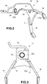
- FIG. 2 and 3 of the accompanying drawings show a fork 10 for a gearbox having a geometry similar to that of the fork of Fig. 1 , but made as a single body from a single piece of sheet metal.
- the two prongs 16 are integrally connected to the mounting plate 22a by means of respective bends, or bent portions, indicated with P, in this case right-angle bends.
- bends are unobtainable with the bending techniques known to date, especially in the case of components, such as the forks for gearboxes or the brackets for injectors of internal combustion engines, obtained from metal sheet with a thickness of a few millimeters, if not with significant problems of geometric and dimensional precision, which make further machining on the component necessary to comply with the required tolerances and therefore make the manufacturing process more complex and expensive overall. Furthermore, obtaining these bends with the bending techniques known to date would entail a reduction in the mechanical characteristics of the material and an increase in the stresses on said material, with a consequent risk of cracking. For these reasons, a fork for a gearbox such as the one shown in Fig. 1 has never before been manufactured from a single sheet metal piece.
- the object of this invention is therefore to provide a method which allows metal components to be manufactured, in particular components for motor vehicles, such as forks for gearboxes or mounting brackets for injectors of internal combustion engines, from a single piece of sheet metal by means of at least one bending operation, ensuring high dimensional accuracy, counteracting the springback of the material after bending and reducing the stresses on the material during bending.
- the invention is based on the idea of carrying out the bending operation (or operations) necessary for manufacturing the component by urging the sheet metal piece against a die with a punch,
- the ratio between the area of the bent portion to be obtained between the neutral axis and the real extrados surface, i.e. the extrados surface that would actually be obtained by bending the piece of sheet metal with the desired angle and bending radius, and the area of the bent portion to be obtained between the neutral axis and the theoretical extrados surface is chosen.
- This correction factor is in the range of 4% to 16%.
- the subject matter of this invention further includes a fork for a gearbox and a mounting bracket for injectors of internal combustion engines, as specified respectively in independent claim 5 and independent claim 6, as examples of metal components obtained by means of the method of the invention.
- Fig. 4 and 5 show, as a further example of a component, in particular for a motor vehicle, obtainable with the method according to the invention from a single piece of sheet metal, a mounting bracket 30 for mounting injectors for internal combustion engines.
- the mounting bracket 30 substantially forms a central fixing portion 32, having a through hole 34 for the insertion of a fixing screw (not shown) for fixing the bracket 30 to the motor head, and a fork portion 36 extending from the central fixing portion 32 (or, alternatively, a pair of fork portions extending on opposite sides relative to the central fixing portion 32) for mounting a respective injector (known per se and not illustrated).
- the mounting bracket 30 shown in Fig. 4 and 5 is obtained starting from a single piece of sheet metal suitably shaped by performing a series of bending operations.
- P indicates the bends of the mounting bracket 30 made according to the method of this invention.
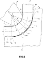
- S I and S E respectively indicate the theoretical surfaces (i.e. as designed) of the intrados and extrados of the bend P.
- the theoretical surface of the intrados S I of the bend P extends between a point P I1 and a point P I2
- the theoretical surface of the extrados S E of the bend P extends between a point P E1 and a point P E2 .
- the extrados surface S E is drawn in Fig. 6 with a dashed line.
- the neutral axis of the bend P is indicated with a N , while the bending angle is indicated with ⁇ .
- the radius of curvature of the theoretical surface of the intrados S I is indicated with r I
- the radius of curvature of the theoretical surface of the extrados S E is indicated with r E .
- s indicates the thickness of the sheet.
- the bend P is obtained by plastically deforming the material of the sheet between a die 50 and a punch 52, having respective suitably shaped working surfaces (i.e. respective surfaces intended to come into contact with the material to be processed) 54 and 56.
- the working surface 54 includes a first substantially flat surface portion 54a, a second substantially flat surface portion 54b, which is inclined with respect to the first surface portion 54a by an angle equal to the bending angle ⁇ , and a curved surface portion 54c, which joins the two flat surface portions 54a and 54b to each other.
- the curved surface portion 54c of the working surface 54 of the die 50 does not have a profile corresponding to that of the theoretical extrados surface S E , but rather has a radius of curvature r M greater than the radius of curvature r E of the theoretical extrados surface S E .
- the curved surface portion 54c of the working surface 54 of the die 50 used in the method according to the invention to obtain the bend P has a less pronounced curvature than a die having a curved working surface portion with a profile corresponding to that of the theoretical extrados surface S E of the bend P.
- the reduction of the curvature involves a shortening of the extrados of the curved part of the sheet. It will be observed ( Fig. 6 ) that the curved surface portion 54c of the working surface 54 of the die has a shorter length than the length of the theoretical extrados surface S E . This shorter length reduces stretching and therefore the tensile stress in the radially outermost part of the bent or curved part of the sheet. It will be appreciated that by reducing the tensile stress the cause of springback and crack formation is reduced.
- C indicates the center of the theoretical extrados surface S E , having a radius of curvature r E .
- the radius of curvature r M of the curved surface portion 54c of the working surface 54 of the die 50 is calculated from the radius of curvature r E of the theoretical extrados surface S E of the bend P taking into account a correction factor k dependent on the tensile strength of the material, the bending angle ⁇ and the thickness s of the sheet.
- C' indicates the center of curvature of the curved surface portion 54c of the working surface 54 of the die 50.
- the correction factor k is a reduction factor to be applied to the theoretical area of the stretched zone of the bend P, i.e. to the area of the bent zone P wherein the material is subjected to traction, therefore to the area comprised in the radial direction between the neutral axis a N and the theoretical extrados surface S E and in a circumferential direction between the radius r M passing through the point and P M1 (beginning of the bend P) and the radius r M passing through the point P M2 (end of the bend P).
- the curved surface portion 54c of the die 50 corresponds to the extrados surface of the corrected bend of the aforementioned correction factor k, i.e. the extrados surface of a bend wherein the area of the stretched zone is reduced by this correction factor relative to the theoretical area of the stretched zone.
- the correction factor k is in the range of 4% to 16%.
- the neutral axis a N is positioned at 5/12 of the thickness s of the material, whereby the curved portion of the neutral axis at the bend P has a radius of curvature r N equal to 7.08 mm
- the theoretical area of the stretched zone of the bend P will be equal to 39.17 mm 2 .
- the corrected area will be equal to 34.28 mm 2 .
- the profile of the curved surface portion 54c of the working surface 54 of the die 50 is thus defined, which will be an arc passing through the points P M1 and P M2 and having the radius of curvature r M calculated above.
Landscapes
- Engineering & Computer Science (AREA)
- Mechanical Engineering (AREA)
- General Engineering & Computer Science (AREA)
- Chemical & Material Sciences (AREA)
- Combustion & Propulsion (AREA)
- Manufacturing & Machinery (AREA)
- Bending Of Plates, Rods, And Pipes (AREA)
Priority Applications (1)
| Application Number | Priority Date | Filing Date | Title |
|---|---|---|---|
| EP20200802.5A EP3982013A1 (de) | 2020-10-08 | 2020-10-08 | Verfahren zur herstellung von metallteilen aus einem einzigen blechteil |
Applications Claiming Priority (1)
| Application Number | Priority Date | Filing Date | Title |
|---|---|---|---|
| EP20200802.5A EP3982013A1 (de) | 2020-10-08 | 2020-10-08 | Verfahren zur herstellung von metallteilen aus einem einzigen blechteil |
Publications (1)
| Publication Number | Publication Date |
|---|---|
| EP3982013A1 true EP3982013A1 (de) | 2022-04-13 |
Family
ID=73598655
Family Applications (1)
| Application Number | Title | Priority Date | Filing Date |
|---|---|---|---|
| EP20200802.5A Pending EP3982013A1 (de) | 2020-10-08 | 2020-10-08 | Verfahren zur herstellung von metallteilen aus einem einzigen blechteil |
Country Status (1)
| Country | Link |
|---|---|
| EP (1) | EP3982013A1 (de) |
Citations (7)
| Publication number | Priority date | Publication date | Assignee | Title |
|---|---|---|---|---|
| US4294095A (en) * | 1978-11-22 | 1981-10-13 | Nippon Steel Corporation | Process for fabricating heavy wall to pipe |
| JPH11101170A (ja) * | 1997-09-26 | 1999-04-13 | Kubota Corp | エンジンの燃料噴射器取付け装置 |
| JP2003083448A (ja) * | 2001-09-07 | 2003-03-19 | Suzuki Motor Corp | 変速機のシフト装置及びシフト装置の製造方法 |
| JP2004268044A (ja) * | 2003-03-04 | 2004-09-30 | Amada Co Ltd | 曲げ金型並びにその加工方法及び加工装置 |
| JP2007083255A (ja) * | 2005-09-20 | 2007-04-05 | Amada Co Ltd | ヘミング金型 |
| EP2053283B1 (de) | 2007-10-24 | 2010-08-18 | C.R.F. Società Consortile per Azioni | Gangschaltgabel für ein Getriebe |
| US20200292429A1 (en) * | 2017-08-23 | 2020-09-17 | Jfe Steel Corporation | Deformation limit evaluation method for sheared surface of metal sheet, crack prediction method, and press die designing method |
-
2020
- 2020-10-08 EP EP20200802.5A patent/EP3982013A1/de active Pending
Patent Citations (7)
| Publication number | Priority date | Publication date | Assignee | Title |
|---|---|---|---|---|
| US4294095A (en) * | 1978-11-22 | 1981-10-13 | Nippon Steel Corporation | Process for fabricating heavy wall to pipe |
| JPH11101170A (ja) * | 1997-09-26 | 1999-04-13 | Kubota Corp | エンジンの燃料噴射器取付け装置 |
| JP2003083448A (ja) * | 2001-09-07 | 2003-03-19 | Suzuki Motor Corp | 変速機のシフト装置及びシフト装置の製造方法 |
| JP2004268044A (ja) * | 2003-03-04 | 2004-09-30 | Amada Co Ltd | 曲げ金型並びにその加工方法及び加工装置 |
| JP2007083255A (ja) * | 2005-09-20 | 2007-04-05 | Amada Co Ltd | ヘミング金型 |
| EP2053283B1 (de) | 2007-10-24 | 2010-08-18 | C.R.F. Società Consortile per Azioni | Gangschaltgabel für ein Getriebe |
| US20200292429A1 (en) * | 2017-08-23 | 2020-09-17 | Jfe Steel Corporation | Deformation limit evaluation method for sheared surface of metal sheet, crack prediction method, and press die designing method |
Similar Documents
| Publication | Publication Date | Title |
|---|---|---|
| US5404690A (en) | Impact beam assembly method and apparatus | |
| US5771737A (en) | Method for producing a propeller shaft | |
| EP3194093B1 (de) | Verfahren zur herstellung einer hohlen zahnstange | |
| CA2774285C (en) | A component, especially a control arm for a vehicle | |
| EP2857118A1 (de) | Verfahren zur herstellung eines rohrförmigen teils mit unterschiedlichen durchmessern und giessform | |
| JP5959702B1 (ja) | プレス成形品の製造方法及びプレス成形型 | |
| US10562138B2 (en) | Method for manufacturing rack bar | |
| US6845560B2 (en) | Method for manufacturing a hollow rack shaft | |
| KR20100097055A (ko) | 비틀림 프로파일 형상의 자동차부품을 제조하기 위한 방법 | |
| CN115365318A (zh) | 形成车辆结构纵梁的价值流法 | |
| US9003852B2 (en) | Sheet metal blank | |
| EP3006133B1 (de) | Verfahren zur herstellung eines stahlrohrs | |
| JP4992048B2 (ja) | 形状凍結性に優れたプレス成形部品のプレス成形方法 | |
| JP2006274436A (ja) | 部品用の断面形状をもつ曲管用のフェライト系ステンレス鋼板および鋼管 | |
| DE102011121904A1 (de) | Verfahren zur scherenden Bearbeitung von Blechen mit einer anschließenden Umformung sowie ein hierzu bestimmtes Schneidwerkzeug | |
| CZ251596A3 (cs) | Trubka pro použití při výrobě součástí motorových vozidel a náprava motorového vozidla s touto trubkou | |
| US20200188977A1 (en) | Method for producing spring strut forks | |
| US11124032B2 (en) | Method for producing motor vehicle controls and the resulting motor vehicle control | |
| US20080276888A1 (en) | Cams for Built-Up Camshafts | |
| KR102325591B1 (ko) | 강판의 단굽힘 방법 및 장치 그리고 강관의 제조 방법 및 설비 | |
| IT201900005704A1 (it) | Procedimento per la realizzazione di componenti metallici, in particolare componenti per veicoli a motore, quali forcelle per cambi di velocità e staffe di supporto per iniettori di motori a combustione interna, a partire da un singolo pezzo di lamiera | |
| CN110038975B (zh) | 用于制造弯曲的扭转型材的方法以及扭转型材 | |
| EP4570397A1 (de) | Verfahren zur herstellung eines pressgeformten produkts | |
| US9283602B2 (en) | Process and apparatus for producing a hollow body, and hollow body | |
| Ogawa et al. | Effect of cut-off side stiffness on stretch flangeability in high-strength steel |
Legal Events
| Date | Code | Title | Description |
|---|---|---|---|
| PUAI | Public reference made under article 153(3) epc to a published international application that has entered the european phase |
Free format text: ORIGINAL CODE: 0009012 |
|
| STAA | Information on the status of an ep patent application or granted ep patent |
Free format text: STATUS: THE APPLICATION HAS BEEN PUBLISHED |
|
| AK | Designated contracting states |
Kind code of ref document: A1 Designated state(s): AL AT BE BG CH CY CZ DE DK EE ES FI FR GB GR HR HU IE IS IT LI LT LU LV MC MK MT NL NO PL PT RO RS SE SI SK SM TR |
|
| STAA | Information on the status of an ep patent application or granted ep patent |
Free format text: STATUS: REQUEST FOR EXAMINATION WAS MADE |
|
| 17P | Request for examination filed |
Effective date: 20221013 |
|
| RBV | Designated contracting states (corrected) |
Designated state(s): AL AT BE BG CH CY CZ DE DK EE ES FI FR GB GR HR HU IE IS IT LI LT LU LV MC MK MT NL NO PL PT RO RS SE SI SK SM TR |
|
| STAA | Information on the status of an ep patent application or granted ep patent |
Free format text: STATUS: EXAMINATION IS IN PROGRESS |
|
| 17Q | First examination report despatched |
Effective date: 20250409 |